EP1249642A1 - Control apparatus for automatic transmission - Google Patents
Control apparatus for automatic transmission Download PDFInfo
- Publication number
- EP1249642A1 EP1249642A1 EP20020007832 EP02007832A EP1249642A1 EP 1249642 A1 EP1249642 A1 EP 1249642A1 EP 20020007832 EP20020007832 EP 20020007832 EP 02007832 A EP02007832 A EP 02007832A EP 1249642 A1 EP1249642 A1 EP 1249642A1
- Authority
- EP
- European Patent Office
- Prior art keywords
- speed
- change
- engagement
- control
- clutch
- Prior art date
- Legal status (The legal status is an assumption and is not a legal conclusion. Google has not performed a legal analysis and makes no representation as to the accuracy of the status listed.)
- Granted
Links
Images


Classifications
-
- B—PERFORMING OPERATIONS; TRANSPORTING
- B60—VEHICLES IN GENERAL
- B60W—CONJOINT CONTROL OF VEHICLE SUB-UNITS OF DIFFERENT TYPE OR DIFFERENT FUNCTION; CONTROL SYSTEMS SPECIALLY ADAPTED FOR HYBRID VEHICLES; ROAD VEHICLE DRIVE CONTROL SYSTEMS FOR PURPOSES NOT RELATED TO THE CONTROL OF A PARTICULAR SUB-UNIT
- B60W10/00—Conjoint control of vehicle sub-units of different type or different function
- B60W10/04—Conjoint control of vehicle sub-units of different type or different function including control of propulsion units
- B60W10/06—Conjoint control of vehicle sub-units of different type or different function including control of propulsion units including control of combustion engines
-
- B—PERFORMING OPERATIONS; TRANSPORTING
- B60—VEHICLES IN GENERAL
- B60W—CONJOINT CONTROL OF VEHICLE SUB-UNITS OF DIFFERENT TYPE OR DIFFERENT FUNCTION; CONTROL SYSTEMS SPECIALLY ADAPTED FOR HYBRID VEHICLES; ROAD VEHICLE DRIVE CONTROL SYSTEMS FOR PURPOSES NOT RELATED TO THE CONTROL OF A PARTICULAR SUB-UNIT
- B60W10/00—Conjoint control of vehicle sub-units of different type or different function
- B60W10/04—Conjoint control of vehicle sub-units of different type or different function including control of propulsion units
-
- B—PERFORMING OPERATIONS; TRANSPORTING
- B60—VEHICLES IN GENERAL
- B60W—CONJOINT CONTROL OF VEHICLE SUB-UNITS OF DIFFERENT TYPE OR DIFFERENT FUNCTION; CONTROL SYSTEMS SPECIALLY ADAPTED FOR HYBRID VEHICLES; ROAD VEHICLE DRIVE CONTROL SYSTEMS FOR PURPOSES NOT RELATED TO THE CONTROL OF A PARTICULAR SUB-UNIT
- B60W10/00—Conjoint control of vehicle sub-units of different type or different function
- B60W10/10—Conjoint control of vehicle sub-units of different type or different function including control of change-speed gearings
- B60W10/11—Stepped gearings
- B60W10/115—Stepped gearings with planetary gears
-
- B—PERFORMING OPERATIONS; TRANSPORTING
- B60—VEHICLES IN GENERAL
- B60W—CONJOINT CONTROL OF VEHICLE SUB-UNITS OF DIFFERENT TYPE OR DIFFERENT FUNCTION; CONTROL SYSTEMS SPECIALLY ADAPTED FOR HYBRID VEHICLES; ROAD VEHICLE DRIVE CONTROL SYSTEMS FOR PURPOSES NOT RELATED TO THE CONTROL OF A PARTICULAR SUB-UNIT
- B60W30/00—Purposes of road vehicle drive control systems not related to the control of a particular sub-unit, e.g. of systems using conjoint control of vehicle sub-units, or advanced driver assistance systems for ensuring comfort, stability and safety or drive control systems for propelling or retarding the vehicle
- B60W30/18—Propelling the vehicle
- B60W30/1819—Propulsion control with control means using analogue circuits, relays or mechanical links
-
- F—MECHANICAL ENGINEERING; LIGHTING; HEATING; WEAPONS; BLASTING
- F16—ENGINEERING ELEMENTS AND UNITS; GENERAL MEASURES FOR PRODUCING AND MAINTAINING EFFECTIVE FUNCTIONING OF MACHINES OR INSTALLATIONS; THERMAL INSULATION IN GENERAL
- F16H—GEARING
- F16H61/00—Control functions within control units of change-speed- or reversing-gearings for conveying rotary motion ; Control of exclusively fluid gearing, friction gearing, gearings with endless flexible members or other particular types of gearing
- F16H61/04—Smoothing ratio shift
- F16H61/06—Smoothing ratio shift by controlling rate of change of fluid pressure
- F16H61/061—Smoothing ratio shift by controlling rate of change of fluid pressure using electric control means
-
- B—PERFORMING OPERATIONS; TRANSPORTING
- B60—VEHICLES IN GENERAL
- B60W—CONJOINT CONTROL OF VEHICLE SUB-UNITS OF DIFFERENT TYPE OR DIFFERENT FUNCTION; CONTROL SYSTEMS SPECIALLY ADAPTED FOR HYBRID VEHICLES; ROAD VEHICLE DRIVE CONTROL SYSTEMS FOR PURPOSES NOT RELATED TO THE CONTROL OF A PARTICULAR SUB-UNIT
- B60W2540/00—Input parameters relating to occupants
- B60W2540/10—Accelerator pedal position
-
- B—PERFORMING OPERATIONS; TRANSPORTING
- B60—VEHICLES IN GENERAL
- B60W—CONJOINT CONTROL OF VEHICLE SUB-UNITS OF DIFFERENT TYPE OR DIFFERENT FUNCTION; CONTROL SYSTEMS SPECIALLY ADAPTED FOR HYBRID VEHICLES; ROAD VEHICLE DRIVE CONTROL SYSTEMS FOR PURPOSES NOT RELATED TO THE CONTROL OF A PARTICULAR SUB-UNIT
- B60W2710/00—Output or target parameters relating to a particular sub-units
- B60W2710/06—Combustion engines, Gas turbines
- B60W2710/0666—Engine torque
-
- F—MECHANICAL ENGINEERING; LIGHTING; HEATING; WEAPONS; BLASTING
- F16—ENGINEERING ELEMENTS AND UNITS; GENERAL MEASURES FOR PRODUCING AND MAINTAINING EFFECTIVE FUNCTIONING OF MACHINES OR INSTALLATIONS; THERMAL INSULATION IN GENERAL
- F16H—GEARING
- F16H61/00—Control functions within control units of change-speed- or reversing-gearings for conveying rotary motion ; Control of exclusively fluid gearing, friction gearing, gearings with endless flexible members or other particular types of gearing
- F16H61/04—Smoothing ratio shift
- F16H2061/0444—Smoothing ratio shift during fast shifting over two gearsteps, e.g. jumping from fourth to second gear
-
- F—MECHANICAL ENGINEERING; LIGHTING; HEATING; WEAPONS; BLASTING
- F16—ENGINEERING ELEMENTS AND UNITS; GENERAL MEASURES FOR PRODUCING AND MAINTAINING EFFECTIVE FUNCTIONING OF MACHINES OR INSTALLATIONS; THERMAL INSULATION IN GENERAL
- F16H—GEARING
- F16H61/00—Control functions within control units of change-speed- or reversing-gearings for conveying rotary motion ; Control of exclusively fluid gearing, friction gearing, gearings with endless flexible members or other particular types of gearing
- F16H61/04—Smoothing ratio shift
- F16H2061/0451—Smoothing ratio shift during swap-shifts, i.e. gear shifts between different planetary units, e.g. with double transitions shift involving three or more friction members
-
- F—MECHANICAL ENGINEERING; LIGHTING; HEATING; WEAPONS; BLASTING
- F16—ENGINEERING ELEMENTS AND UNITS; GENERAL MEASURES FOR PRODUCING AND MAINTAINING EFFECTIVE FUNCTIONING OF MACHINES OR INSTALLATIONS; THERMAL INSULATION IN GENERAL
- F16H—GEARING
- F16H61/00—Control functions within control units of change-speed- or reversing-gearings for conveying rotary motion ; Control of exclusively fluid gearing, friction gearing, gearings with endless flexible members or other particular types of gearing
- F16H61/04—Smoothing ratio shift
- F16H2061/0455—Smoothing ratio shift during shifts involving three or more shift members, e.g. release of 3-4 clutch, 2-4 brake and apply of forward clutch C1
-
- F—MECHANICAL ENGINEERING; LIGHTING; HEATING; WEAPONS; BLASTING
- F16—ENGINEERING ELEMENTS AND UNITS; GENERAL MEASURES FOR PRODUCING AND MAINTAINING EFFECTIVE FUNCTIONING OF MACHINES OR INSTALLATIONS; THERMAL INSULATION IN GENERAL
- F16H—GEARING
- F16H2200/00—Transmissions for multiple ratios
- F16H2200/20—Transmissions using gears with orbital motion
- F16H2200/2002—Transmissions using gears with orbital motion characterised by the number of sets of orbital gears
- F16H2200/2007—Transmissions using gears with orbital motion characterised by the number of sets of orbital gears with two sets of orbital gears
-
- F—MECHANICAL ENGINEERING; LIGHTING; HEATING; WEAPONS; BLASTING
- F16—ENGINEERING ELEMENTS AND UNITS; GENERAL MEASURES FOR PRODUCING AND MAINTAINING EFFECTIVE FUNCTIONING OF MACHINES OR INSTALLATIONS; THERMAL INSULATION IN GENERAL
- F16H—GEARING
- F16H2200/00—Transmissions for multiple ratios
- F16H2200/20—Transmissions using gears with orbital motion
- F16H2200/2097—Transmissions using gears with orbital motion comprising an orbital gear set member permanently connected to the housing, e.g. a sun wheel permanently connected to the housing
-
- F—MECHANICAL ENGINEERING; LIGHTING; HEATING; WEAPONS; BLASTING
- F16—ENGINEERING ELEMENTS AND UNITS; GENERAL MEASURES FOR PRODUCING AND MAINTAINING EFFECTIVE FUNCTIONING OF MACHINES OR INSTALLATIONS; THERMAL INSULATION IN GENERAL
- F16H—GEARING
- F16H3/00—Toothed gearings for conveying rotary motion with variable gear ratio or for reversing rotary motion
- F16H3/44—Toothed gearings for conveying rotary motion with variable gear ratio or for reversing rotary motion using gears having orbital motion
- F16H3/62—Gearings having three or more central gears
- F16H3/66—Gearings having three or more central gears composed of a number of gear trains without drive passing from one train to another
- F16H3/663—Gearings having three or more central gears composed of a number of gear trains without drive passing from one train to another with conveying rotary motion between axially spaced orbital gears, e.g. RAVIGNEAUX
-
- F—MECHANICAL ENGINEERING; LIGHTING; HEATING; WEAPONS; BLASTING
- F16—ENGINEERING ELEMENTS AND UNITS; GENERAL MEASURES FOR PRODUCING AND MAINTAINING EFFECTIVE FUNCTIONING OF MACHINES OR INSTALLATIONS; THERMAL INSULATION IN GENERAL
- F16H—GEARING
- F16H61/00—Control functions within control units of change-speed- or reversing-gearings for conveying rotary motion ; Control of exclusively fluid gearing, friction gearing, gearings with endless flexible members or other particular types of gearing
- F16H61/68—Control functions within control units of change-speed- or reversing-gearings for conveying rotary motion ; Control of exclusively fluid gearing, friction gearing, gearings with endless flexible members or other particular types of gearing specially adapted for stepped gearings
- F16H61/684—Control functions within control units of change-speed- or reversing-gearings for conveying rotary motion ; Control of exclusively fluid gearing, friction gearing, gearings with endless flexible members or other particular types of gearing specially adapted for stepped gearings without interruption of drive
- F16H61/686—Control functions within control units of change-speed- or reversing-gearings for conveying rotary motion ; Control of exclusively fluid gearing, friction gearing, gearings with endless flexible members or other particular types of gearing specially adapted for stepped gearings without interruption of drive with orbital gears
-
- F—MECHANICAL ENGINEERING; LIGHTING; HEATING; WEAPONS; BLASTING
- F16—ENGINEERING ELEMENTS AND UNITS; GENERAL MEASURES FOR PRODUCING AND MAINTAINING EFFECTIVE FUNCTIONING OF MACHINES OR INSTALLATIONS; THERMAL INSULATION IN GENERAL
- F16H—GEARING
- F16H63/00—Control outputs from the control unit to change-speed- or reversing-gearings for conveying rotary motion or to other devices than the final output mechanism
- F16H63/40—Control outputs from the control unit to change-speed- or reversing-gearings for conveying rotary motion or to other devices than the final output mechanism comprising signals other than signals for actuating the final output mechanisms
- F16H63/50—Signals to an engine or motor
- F16H63/502—Signals to an engine or motor for smoothing gear shifts
Definitions
- the present invention relates to a control apparatus for an automatic transmission, and more particularly to an art for smoothly performing a speed-change operation requiring phasic changeover of engagement and release of engagement elements between speed-change stages.
- an automatic transmission is designed to change over power-transmission paths extending through speed-change elements composed of planetary gears by engaging or releasing frictional engagement elements and to establish a plurality of speed-change stages by changing a gear ratio.
- operations of the engagement elements for upshift or downshift are generally performed as follows. That is, basically, for a plurality of engagement elements or a single engagement element which are or is engaged to establish a certain speed-change stage, another one of the engagement elements is engaged additionally, or one engagement element that is engaged is released.
- a so-called changeover operation of the engagement elements is performed if it is inevitable for reasons of the construction of a gear train. That is, while the engagement elements that are engaged are released, the other engagement elements are engaged.
- the changeover operation of engagement elements is not limited to simple changeover of two elements but may be complicated changeover of four elements if necessary.
- a so-called skip speed-change operation for shifting to a specific one of a multitude of speed-change stages at a stretch is an example requiring such changeover of four elements.
- a multiple changeover speed-change operation requires control for engaging or releasing the engagement elements in a certain order, whereby it becomes indispensable to perform speed-change operations in a phasic manner.
- the engagement elements are engaged or released in a certain order, the following problems are caused in this case. That is, phasic occurrence of a shock is likely during a multiple changeover speed-change operation, and the interval between speed-change operations tends to increase. The phasic occurrence of a shock during a speed-change operation or an increase in the interval between speed-change operations causes an undesirable feeling of incongruity to a driver. Timings for engaging or releasing the engagement elements are crucial in solving such problems. However, for reasons of errors among individual automatic transmissions or operational states of the vehicle, it is difficult to perfectly match the timings for engaging or releasing the engagement elements.
- Figs. 1 to 15 show a first embodiment of an automatic transmission to which a control apparatus according to the present invention is applied.
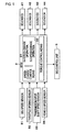
- Fig. 1 is a block diagram of a configuration of a signal system of the control apparatus. As shown in Fig. 1, this control apparatus has a speed-change control means 21 in an electronic control unit (ECU) 2, which is a central component member of the control apparatus.
- ECU electronice control unit
- the control apparatus has various sensors as an input means for inputting various pieces of information to the ECU 2, namely, an engine (E/G) speed sensor 31 for detecting an engine speed of a vehicle, a throttle opening sensor 32 for detecting an engine load, a transmission input-shaft speed sensor 33 for detecting an input speed of a transmission, and a vehicle speed sensor 34 for detecting a vehicle speed from a speed of an output shaft of the transmission.
- the control apparatus has a plurality of solenoids as an output means operating by the output of a drive signal based on control information, namely, solenoids 1 to 4 as actuators for solenoid valves 41 to 44 disposed in a hydraulic control unit, which will be described later in detail with reference to Fig. 5.
- the control apparatus also has an input torque control means 22 as an output means for outputting a signal for adjusting a throttle opening to an engine electronic control unit 5.
- Fig. 2 is a skeleton diagram showing a six-speed gear train for FR vehicles as an example of a speed-change mechanism controlled by the aforementioned control apparatus.
- This gear train is composed of a torque converter 7 and a speed-change mechanism.
- the torque converter 7 is equipped with a lock-up clutch.
- the speed-change mechanism has six forward stages and one backward stage and is composed of a planetary gear set G of Ravigneaux type and a deceleration gear G1 of simple planetary type.
- the planetary gear set G which is a main component member of the speed-change mechanism, is constructed of a gear set of Ravigneaux type.
- the gear set is composed of sun gears S2, S3 having different diameters, a ring gear R2, a long pinion gear P2 that meshes with the sun gear S2 with the larger diameter in a circumscribed manner and that meshes with the ring gear R2 in an inscribed manner, a short pinion gear P3 that meshes with the sun gear S3 with the smaller diameter in a circumscribed manner and that also meshes with the long pinion gear P2 in a circumscribed manner, and a carrier C2 supporting both the pinion gears P2, P3.
- the small-diameter sun gear S3 of the planetary gear set G is coupled to a multiple-disc clutch (C-1) (Hereinafter, each engagement element is marked with a symbol, which precedes the name of the element.).
- the large-diameter sun gear S2 is coupled to a multi-disc C-3 clutch and can be hooked to an automatic transmission case 10 by a B-1 brake constructed of a band brake. Furthermore, the large-diameter sun gear S2 can be hooked to the automatic transmission case 10 by a multiple-disc B-2 brake and an F-1 one-way clutch, which are disposed in parallel with the B-1 brake.
- the carrier C2 is coupled to an input shaft 11 via a C-2 clutch as a multiple-disc engagement element, and can be hooked to the transmission case 10 by a multiple-disc B-3 brake. Also, the carrier C2 can be hooked to the transmission case 10 by an F-2 one-way clutch in such a manner as to rotate in one direction.
- the ring gear R2 is coupled to an output shaft 19.
- the deceleration planetary gear G1 is constructed of a simple planetary gear.
- a ring gear R1 as an input element of the deceleration planetary gear G1 is coupled to the input shaft 11.
- a carrier C1 as an output element of the deceleration planetary gear G1 is coupled to the small-diameter sun gear S3 via the C-1 clutch and to the large-diameter sun gear S2 via the C-3 clutch.
- a sun gear S1 as a stationary element for gaining a counterforce is fixed to the transmission case 10.
- Fig. 3 is an engagement chart showing how speed-change stages to be established are related to engagement and release of the engagement elements of this automatic transmission, that is, the clutches, the brakes, and the one-way clutches.
- each blank filled in with O, each unfilled blank, each blank filled in with ⁇ , and each blank filled in with ⁇ represent engagement, release, engagement for engine braking, and engagement that does not directly affect establishment of a speed-change stage, respectively.
- Fig. 4 is a speed diagram showing how speed-change stages established through engagement of each of the clutches, brakes, and one-way clutches (Engagement is denoted by •.) are related to speed ratios among the speed-change elements.
- a first-speed (1st) stage is established through engagement of the C-1 clutch and the B-3 brake (Automatic engagement of the F-2 one-way clutch is adopted instead of engagement of the B-3 brake as is apparent by referring to an operational chart in this embodiment.
- Engagement of the F-2 one-way clutch is adopted as the equivalent of engagement of the B-3 brake because the F-1 one-way clutch for automatically releasing an engaging force upon engagement of the B-1 brake is used to avoid complication of hydraulic pressure control for changeover between the B-3 brake and the B-1 brake during a 1-2 speed-change operation that will be described later and to simplify release control of the B-3 brake.).
- rotation that has been transmitted from the input shaft 11 via the deceleration planetary gear G1 while being decelerated is input to the small-diameter sun gear S3 via the C-1 clutch, gains a counterforce from the carrier C2 that has been hooked through engagement of the F-2 one-way clutch, and is output to the output shaft 19 as decelerated rotation of the ring gear R2 at a maximum deceleration ratio.
- a second-speed (2nd) stage is then established through engagement of the C-1 clutch and engagement of the B-2 brake, which makes engagement of the F-1 one-way clutch effective. Engagement of the F-1 one-way clutch and the B-2 brake is equivalent to engagement of the B-1 brake (It will be described later in detail why engagement of the F-1 one-way clutch and the B-2 brake is equivalent to engagement of the B-1 brake.).
- a third-speed (3rd) stage is established through simultaneous engagement of the C-1 clutch and the C-3 clutch.
- rotation that has been transmitted from the input shaft 11 via the deceleration planetary gear G1 while being decelerated is simultaneously input to the large-diameter sun gear S2 and the small-diameter sun gear S3 via the C-1 clutch and the C-3 clutch respectively, so that the planetary gear set assumes a direct-coupled state. Therefore, rotation of the ring gear R2, which is the same as rotation that has been input to both the sun gears, is output to the output shaft 19 as rotation that has been decelerated with respect to rotation of the input shaft 11.
- a fourth-speed (4th) stage is established through simultaneous engagement of the C-1 clutch and the C-2 clutch.
- rotation that has been transmitted from the input shaft 11 via the deceleration planetary gear G1 while being decelerated is input to the small-diameter sun gear S3 via the C-1 clutch
- non-decelerated rotation that has been input from the input shaft 11 via the C-2 clutch is input to the carrier C2.
- Intermediate rotation between the two input rotations is output to the output shaft 19 as rotation of the ring gear R2, which has been slightly decelerated with respect to rotation of the input shaft 11.
- a fifth-speed (5th) stage is then established through simultaneous engagement of the C-2 clutch and the C-3 clutch.
- rotation that has been transmitted from the input shaft 11 via the deceleration planetary gear G1 while being decelerated is input to the large-diameter sun gear S2 via the C-3 clutch
- non-decelerated rotation that has been input from the input shaft 11 via the C-2 clutch is input to the carrier C2.
- Rotation of the ring gear R2 which has been slightly accelerated with respect to rotation of the input shaft 11, is output to the output shaft 19.
- a sixth-speed (6th) stage is then established through engagement of the C-2 clutch and the B-1 brake.
- non-decelerated rotation is input only to the carrier C2 from the input shaft 11 via the C-2 clutch, gains a counterforce from the sun gear S2 that has been hooked through engagement of the B-1 brake, and is output to the output shaft 19 as further accelerated rotation of the ring gear R2.
- a backward (R) stage is established through engagement of the C-3 clutch and the B-3 brake.
- rotation that has been transmitted from the input shaft 11 via the deceleration planetary gear G1 while being decelerated is input to the large-diameter sun gear S2 via the C-3 clutch, gains a counterforce from the carrier C2 that has been hooked through engagement of the B-3 brake, and is output to the output shaft 19 as reverse rotation of the ring gear R2.
- the F-1 one-way clutch is related to the B-1 brake and the B-2 brake.
- the F-1 one-way clutch coupled to the sun gear S2 is engaged in such a direction as to support a counter torque of the large-diameter sun gear S2 at the second-speed stage, whereby the F-1 one-way clutch can substantially perform the same function as engagement of the B-1 brake.
- the large-diameter sun gear S2 is different from the carrier C2 and is a speed-change element that not only is engaged to achieve the effect of engine braking at the second-speed stage but also is hooked to establish the sixth-speed stage, the B-1 brake is required.
- the large-diameter sun gear S2 rotates reversely with respect to a direction of input rotation upon establishment of the first-speed (1st) stage, but rotates in the direction of input rotation at the third-speed stage or any higher speed stage. Accordingly, the F-1 one-way clutch cannot be directly coupled to a stationary member and thus is disposed in series with the B-2 brake so as to make it possible to control the effectiveness of an engaged state.
- each speed-change stage established as described above is relatively equidistant from its adjacent speed-change stages, so that good speed steps are obtained.
- This gear train does not require multiple changeover of the engagement elements during a normal upshift or downshift operation between two adjacent speed-change stages but requires it during a skip speed-change operation.
- Such a skip speed-change operation is necessary especially during a downshift operation such as a 6-3 or 5-2 speed-change operation (During this speed-change operation, the B-2 brake is always engaged at the second-speed stage or any higher speed stage for the sake of simplification of control. Therefore, automatic engagement of the F-1 one-way clutch plays the same role as engagement of the B-1 brake.).
- the hydraulic control unit for controlling the speed-change mechanism thus constructed by operating hydraulic servos for the aforementioned clutches and brakes is designed such that each of the hydraulic servos for a corresponding one of the engagement elements is controlled directly and independently by a proper solenoid valve on the basis of a solenoid drive signal from the electronic control unit 2 so as to make the aforementioned skip speed-change operation easy to perform.
- this hydraulic circuit is constructed as follows. That is, control valves 45 to 48 are connected in parallel with one another with respect to a line-pressure hydraulic passage 51, which is connected to a circuit for supplying a line pressure (a maximum pressure capable of maintaining the engagement elements in an engaged state in accordance with a running load of the vehicle).
- Fig. 5 indicates this circuit as a block instead of showing its concrete construction.
- Each of the control valves 45 to 48 operates for pressure regulation in accordance with a solenoid pressure applied from a corresponding one of solenoid valves 41 to 44.
- a hydraulic servo 61 for the C-1 clutch is connected to the line-pressure hydraulic passage 51 via a C-1 control valve 45, which is connected at its spool end to a hydraulic passage 52 for a solenoid modulator pressure (a hydraulic pressure that is obtained by reducing a line pressure via a modulator valve so as to increase a gain of pressure regulation by a solenoid valve).
- the C-1 control valve 45 is designed as a spool valve having lands at its opposed ends, and the lands are different in diameter.
- the C-1 control valve 45 is constructed such that a solenoid signal pressure is applied to the large-diameter land end against a spring load applied to the small-diameter land end, that the large-diameter land thereby closes a drain port, that the line-pressure hydraulic passage 51 and the hydraulic servo 61 thereby communicate with each other while the small-diameter land narrows a gap between an inlet port leading to the line-pressure hydraulic passage 51 and an outlet port leading to the hydraulic servo 61, that the small-diameter land closes the inlet port and the large-diameter land opens the drain port as soon as a solenoid pressure is released, and that the hydraulic servo 61 is connected in a drainable manner as a result.
- the solenoid valve 41 is designed as a normal-open linear solenoid valve. Similarly, the solenoid valve 41 is constructed such that a gap between the solenoid-modulator- pressure hydraulic passage 52 and a solenoid-pressure hydraulic passage 53 is adjusted by a load applied to a plunger against a spring load applied to one end of a spool having lands at its opposed ends and that a solenoid pressure is regulated by adjusting an amount of drainage through the solenoid-pressure hydraulic passage 53.
- the C-2 clutch, the B-1 brake, and the C-3 clutch also adopt a parallel circuit construction that is quite similarly composed of the control valves 46, 47, 48, the solenoid valves 42, 43, 44, and solenoid-pressure hydraulic passages 54, 55, 56, respectively.
- the solenoid-pressure hydraulic passages 54, 55, 56 connect the control valves 46, 47, 48 to the solenoid valves 42, 43, 44, respectively.
- the automatic transmission thus constructed requires operation of four engagement elements (the C-1 clutch, the C-2 clutch, the C-3 clutch, and the B-1 brake), for example, during a 6-3 speed-change operation wherein the first speed-change stage is the sixth-speed stage and wherein the second speed-change stage is the third-speed stage that is apart from the sixth-speed stage by three stages.
- the first speed-change stage (the sixth-speed stage) is established through engagement of the first and second engagement elements (the B-1 brake and the C-2 brake), and the second speed-change stage is established through engagement of the third and fourth engagement elements (the C-1 clutch and the C-3 clutch).
- the first speed-change stage is the fifth-speed stage
- operation of four engagement elements (the C-1 clutch, the C-2 clutch, the C-3 clutch, and the F-1 one-way clutch) is also required during a speed-change operation from the fifth-speed stage to the second-speed stage that is apart from the fifth-speed stage by three stages.
- the first, second, third, and fourth engagement elements are the C-2 clutch, the C-3 clutch, the C-1 clutch, and the F-1 one-way clutch, respectively.
- the speed-change control unit is provided with the speed-change control means 21 (see Fig.
- engagement or release of the engagement elements includes a transient slip state leading to complete engagement or complete release. Accordingly, starting to release a certain engagement element means starting to cause it to slip. As regards an engagement element that is operated hydraulically, starting to release it means starting to cause it to slip through a decrease in engaging force. As regards a one-way clutch that is not operated hydraulically, starting to release it means making it free in accordance with a change in rotational direction of a rotational member. Similarly, completing engagement of a certain engagement element means causing it to stop slipping.
- the speed-change control means 21 is designed such that the first speed-change stage (the sixth-speed stage or the fifth-speed stage) is established through operation of two (the C-1 clutch and the B-1 brake) of the aforementioned four engagement elements, that the second speed-change stage (the third-speed stage or the second-speed stage) is established through operation of the other two engagement elements, that a third speed-change stage (the fourth-speed stage or the third-speed stage) is set, and that a speed-change operation from the first speed-change stage (the sixth-speed stage or the fifth-speed stage) to the second speed-change stage (the third-speed stage or the second-speed stage) is shifted to a speed-change operation from the third speed-change stage (the fourth-speed stage or the third-speed stage) to the second speed-change stage (the third-speed stage or the second-speed stage) via a speed-change operation from the first speed-change stage (the sixth-speed stage or the fifth-speed stage) to the third speed-change stage (the fourth-speed stage or the fourth-speed
- the four engagement elements are the C-1 clutch that is engaged during a speed-change operation to the third speed-change stage (the fourth-speed stage or the third-speed stage), the B-1 brake or the C-2 clutch that is released during the speed-change operation, the C-3 clutch or the F-1 one-way clutch that is engaged during a speed-change operation to the second speed-change stage (the third-speed stage or the second-speed stage), and the C-2 clutch or the C-3 clutch that is released during the speed-change operation.
- the speed-change control means 21 of this embodiment is constructed as a program in the control unit.
- the speed-change operation is performed by controlling the hydraulic servos 61 to 64 for the engagement elements through operation of the solenoid valve 42 caused by a solenoid drive signal, which is output on the basis of the program.
- control flowcharts of the speed-change control means 21 for the engagement elements will be described one by one.
- a sub-routine processing for servo activation control is then performed in step S12.
- This processing is designed to maintain a fast fill of a hydraulic pressure for filling a hydraulic servo cylinder for the C-1 clutch and a subsequent piston stroke pressure for narrowing a gap between a hydraulic servo piston and a frictional member of the engagement element.
- This processing is a known processing that is usually performed to engage a clutch.
- a determination on a proceeding degree (Shift R>S_End 1) is made in step S13 on the basis of an indicator (Shift R) for making a determination on a proceeding degree of a speed-change operation.
- the proceeding degree is set as 70% and calculated on the basis of values detected by the transmission input-shaft speed sensor 33 and the vehicle speed sensor 34. Because the result of this determination is negative (No) at the outset, the processing for this determination is continued until the proceeding of the speed-change operation is completed. As soon as the result of the aforementioned determination becomes positive (Yes), a pressure-increasing operation for starting engagement of the C-1 clutch (sweep-up with a gradient of dP C1 a) is started in step S14. To be more specific, this processing is designed to control an electric current value of a drive signal transmitted to a solenoid 1 and operate the solenoid valve 41 shown in Fig.
- step S15 while this pressure-increasing operation is continued, it is determined on the basis of the indicator (Shift R) for the proceeding degree of the speed-change operation whether or not the speed-change operation has reached a state before synchronization with the fourth-speed stage (Shift R>S_End 2), for example, 90%.
- step S15 a processing of increasing the servo hydraulic pressure to a line pressure (sweep-up with a gradient of dP C1 b) is performed in step S16 so as to reliably maintain engagement of the C-1 clutch.
- a processing of determining whether or not the servo hydraulic pressure has reached the line pressure (P C1 >P FULL ) is then repeated in step S17. As soon as the result of the determination in step S17 becomes positive, the 6-4 speed-change control for engagement control of the C-1 clutch is terminated.
- FIG. 7 A control flowchart for releasing the B-1 brake or the first engagement element is shown in Fig. 7.
- This control is started simultaneously with the aforementioned 6-4 speed-change control for engaging the C-1 clutch.
- This processing is intended to prevent the engine from undergoing prefiring due to operational dispersion in the C-1 clutch resulting from aging or a difference among individual transmissions.
- a period for maintaining this predetermined pressure is then monitored in step S23. The processing is continued until the result of the determination (timer t>t_wait) in step S23 becomes positive.
- a processing of gradually reducing the servo hydraulic pressure (sweep-down with a gradient of dP B1 c) is then performed in step S25.
- a determination on a proceeding degree (Shift R) of the speed-change operation is then made in step S26. In this case as well, since the result of the determination in step S26 is negative at the outset, the speed-change operation is repeated through a loop for returning to step S25.
- step S26 If the result of the determination on the proceeding degree of the speed-change operation in step S26 becomes positive (Shift R>S_End 2), a low-pressure processing of completely removing the servo hydraulic pressure of the B-1 brake (sweep-down with a gradient of dP B1 d) is then performed in step S27. This processing is completed automatically as soon as a solenoid valve 3 reaches a full output. Therefore, the 6-4 speed-change control for releasing the B-1 brake is terminated without performing any further monitoring or determining operation.
- FIG. 8 A control flowchart for releasing the C-2 clutch or the second engagement element is shown in Fig. 8.
- step S31 it is determined first in step S31 whether or not the 6-4 speed-change operation has been terminated. If the result of the determination in step S31 is positive, subsequent processings are skipped to terminate the C-2 release control. While the aforementioned case is excluded, it is then determined in step S32 whether or not a shift command to the third-speed stage is fulfilled (3rd determination). Thus, a shift operation to the third-speed stage is distinguished from the other speed-change stages.
- a determination on a proceeding degree (Shift R) of the speed-change operation is started in step S33 so as to determine a timing for starting to release the C-2 clutch.
- An indicator for making a determination on a proceeding degree of the speed-change operation in this case is a value (Shift R_S) that is based on a speed of the input shaft of the transmission.
- the predetermined pressure in this case is the sum of a hydraulic pressure (P C2_ to) suited for a torque input to the C-2 clutch and a hydraulic pressure (P C2_ OS) corresponding to a safety factor.
- the torque input to the C-2 clutch can be calculated by calculating an engine torque from a map of throttle opening and engine speed, calculating a speed ratio from input and output speeds of the torque converter, and multiplying the engine torque thus calculated by the speed ratio.
- the input torque is then converted into a hydraulic pressure by dividing the input torque by a product of a pressure-receiving area of the piston of the hydraulic servo of a corresponding one of the engagement elements, the number of frictional members, an effective radius, and a friction coefficient, and adding a piston stroke pressure to the quotient.
- step S35 a determination on a proceeding degree (Shift R) of the speed-change operation is made (Shift R>S_End 3) in step S35 so as to determine whether or not there is a state prior to synchronization with the fourth-speed stage.
- step S36 it is then determined in step S36 whether or not the servo hydraulic pressure (P C1 ) of the C-1 clutch has exceeded a hydraulic pressure (P C1_ eg*k) required for maintenance of engagement with respect to the input torque (P C1 >P C1_ eg*k).
- P C1_ eg*k a hydraulic pressure required for maintenance of engagement with respect to the input torque
- k is a coefficient and assumes a value of, for example, about 0.7.
- the input torque used in this determination is calculated as described above. If the result of this determination becomes positive, the fourth-speed stage is established completely. Thus, the 4-3 speed-change control is then performed (The 4-3 speed-change control is started.).
- a processing of sweeping down the servo pressure (P C2 ) of the C-2 clutch with a gradient of dP C2 c is first performed in step S37.
- a determination on a proceeding degree (Shift R) of the speed-change operation is made (Shift R>S_End 2) in step S38.
- the sweep-down operation is continued until the result of the determination in step S38 becomes positive.
- a low-pressure processing (sweep-down with a gradient of dP C2 d) is finally performed in step S39 so as to remove the servo hydraulic pressure of the C-2 clutch completely.
- This processing is also completed automatically as soon as a solenoid valve 2 reaches a full output. Therefore, the 4-3 speed-change control for releasing the C-2 clutch is terminated without performing any further monitoring or determining operation. Thus, the C-2 release control is terminated.
- FIG. 10 A control flowchart for engaging the C-3 clutch or the fourth engagement element is shown in Fig. 10.
- This control is substantially identical to the aforementioned engagement control of the C-1 clutch, although they are started at different timings.
- a servo activation control sub-routine processing is then performed in step S52.
- This processing is designed to maintain a fast fill of a hydraulic pressure for filling a hydraulic servo cylinder for the C-3 clutch and a subsequent piston stroke pressure for narrowing a gap between a hydraulic servo piston and a frictional member of the engagement element.
- This processing is a known processing that is usually performed to engage a clutch.
- a determination on a proceeding degree as an indicator (Shift R) for making a determination on a proceeding degree of a speed-change operation is made (Shift R>S_End 1) in step S53.
- the proceeding degree (Shift R) of the speed-change operation has already been described above. Because the result of this determination is negative (No) at the outset, the processing for this determination is continued until the proceeding of the speed-change operation is completed.
- a pressure-increasing operation for starting engagement of the C-3 clutch (sweep-up with a gradient of dP C3 a) is started in step S54.
- step S55 while this pressure-increasing operation is continued, it is determined whether or not the proceeding degree (Shift R) of the speed-change operation has reached synchronization with the third speed stage (Shift R>S_End 2). Because the result of this determination is also negative at the outset, the sweep-up operation is continued through repetition of a loop for returning to step S54 until the proceeding of the speed-change operation is completed. If the result of the determination in step S55 becomes positive, a processing of increasing the servo hydraulic pressure to a line pressure (sweep-up with a gradient of dP C3 b) is performed in step S56 so as to reliably maintain engagement of the C-3 clutch.
- step S57 A processing of determining whether or not the servo hydraulic pressure has reached the line pressure (P C1 >P FULL ) is then repeated in step S57. As soon as the result of the determination in step S57 becomes positive, the 4-3 speed-change control for engagement control of the C-3 clutch is terminated.
- Adjustment of the input torque which is performed by the torque control means in conjunction with the speed-change control, will now be described. Adjustment of the input torque in this embodiment is reduction control of the engine torque.
- Fig. 11 shows a flowchart of torque-reduction control during the 6-3 speed-change control.
- this control it is determined first in step S61 whether or not this control is to be started, on the basis of an indicator (Shift T) for a proceeding degree of the speed-change operation for torque control.
- the proceeding of the speed-change operation is set temporally reversely and is terminated (at a point of termination 0) at the time of completion of 6-4 speed-change control, namely, at a timing (S_End 2) for starting to increase the hydraulic pressure of the hydraulic servo for the C-1 clutch to a line pressure.
- step S61 the result of this determination becomes positive if the C-1 clutch starts to slip, namely, if the 6-3 speed-change control has proceeded to a state slightly before completion of the 6-4 speed-change control (Shift T ⁇ T_End 1).
- the engine torque (EGT_1) is set higher than the engine torque during the normal 6-4 speed-change control.
- step S64 a determination on an elapsed time of torque control is then made (t>t_egcontrol) in step S64.
- the elapsed time (t_egcontrol) is set slightly longer than the aforementioned processing time (T_End 1). If the result of the determination in step S64 becomes positive, a reducing processing for terminating the reduction processing (sweep with a gradient of dEGT1) is performed in step S65. This processing is continued until it is confirmed in step S66 that the engine torque that does not include inertia (EGTorque_noACC) has become equal to or greater than a predetermined value (EGT_2).
- the elapsed time t_egcontrol may be set either equal to the elapsed time t_egcontrol' or shorter than the elapsed time t_egcontrol'.
- the actual torque-down amount is reduced. Therefore, it is possible to eliminate an increase in interval between speed-change operations upon completion of the 6-4 speed-change operation and prevent a feeling of two-phase speed-change operations from being developed.
- a torque-down amount dT is expressed by equations shown below, wherein dTa represents an amount corresponding to inertia that is generated by changes in input speed and engine speed immediately before torque reduction, and wherein dTb represents an engine torque that does not include inertia.
- dT dTa+dTb
- dTa GainA ⁇ T inertia
- dTb GainB ⁇ T E/B
- T inertia represents an inertia torque.
- a gain (GainA) by which the inertia torque T inertia is multiplied is set in accordance with an output speed. As shown in Fig. 12 as an example, during normal power-on downshift, the gain (GainA) assumes a value A, B, C, D, or E for an output speed of Nout 1, Nout 2, Nout 3, Nout 4, or Nout 5, respectively.
- the gain (GainA) is set as a value A', B', C', D', or E', which is smaller than A, B, C, D, or E, respectively.
- T E/B represents an engine torque that does not include inertia.
- a gain (GainB) by which the engine torque T E/B is multiplied is set in accordance with an input torque. As shown in Fig. 13 as an example, during normal power-on downshift, the gain (GainB) assumes a value F, G, H, I, or J for an input torque of Tq_1, Tq_2, Tq_3, Tq_4, or Tq_5, respectively. During the 6-3 speed-change control, the gain (GainB) is set as a value F', G', H', I', or J', which is smaller than F, G, H, I, or J, respectively.
- Fig. 14 is a time chart showing how the four engagement elements operate during the aforementioned 6-3 speed-change control, as a relation between servo hydraulic pressure and speed of the input shaft.
- This time chart schematically shows a speed-change characteristic including the influence of the aforementioned reduction processing of reducing the engine torque. The influence of the reduction processing on the speed-change characteristic will be described later with reference to another time chart.
- Fig. 14 it is assumed that the speed of a brake as an engagement element is positive in the case where its rotation-side element rotates in the same direction as the engine and that the speed of the brake is negative in the opposite case.
- Fig. 14 it is assumed that the speed of a brake as an engagement element is positive in the case where its rotation-side element rotates in the same direction as the engine and that the speed of the brake is negative in the opposite case.
- the servo hydraulic pressure of the B-1 brake is then reduced with a constant gradient, and the servo hydraulic pressure of the C-1 clutch is maintained at a piston stroke pressure, so that the C-1 clutch assumes an engagement-awaiting state.
- the B-1 brake starts to slip, whereby the sun gears S3, S2 proceed in directions of deceleration and acceleration respectively with respect to a point of engagement of the C-2 clutch that is in engagement, as is apparent by referring to Fig. 4.
- the rotational-element side of the B-1 brake starts to rotate positively from a hooked state corresponding to 0.
- the output-element side of the C-3 clutch As for the output-element side of the C-3 clutch, the output-element side is accelerated from negative rotation on the output-element side with respect to decelerated rotation on the input-element side, and proceeds toward positive rotation.
- the C-1 clutch is decelerated in the same direction as and at the same speed as rotation of the engine from a state of positive rotation that has been substantially accelerated with respect to rotation of the engine.
- the servo hydraulic pressure of the C-2 clutch is reduced at a stretch to such a hydraulic pressure that release (slip) of the C-2 clutch is not caused.
- the servo hydraulic pressure of the C-2 clutch is then reduced with a predetermined gradient.
- the 6-4 speed-change operation proceeds toward synchronization with the fourth-speed stage. If it is determined that the operation has proceeded from the speed of the input shaft and reached a state of 70% prior to synchronization with the fourth-speed stage (S_End 1), the servo hydraulic pressure of the C-1 clutch is increased. As a result, engagement (slip) of the C-1 clutch proceeds.
- the servo hydraulic pressure of the C-1 clutch is switched to a state of a rise toward the line pressure.
- the servo hydraulic pressure of the C-2 clutch during descent control is controlled through the reduction control in such a manner as to become a hydraulic pressure suited to reach a state prior to commencement of release when it is determined that a state prior to synchronization with the fourth-speed stage has been achieved (S_End 3). Therefore, at this stage, a second-stage control state for changing a gradient is started.
- the C-2 clutch starts to slip and rotates negatively.
- the C-1 clutch that has been decelerated in a state of deceleration of slip from a state of deceleration of release proceeds toward null rotation of engagement.
- the speed of the C-3 clutch continues to increase. If it is determined that the servo hydraulic pressure of the C-1 clutch has reached the line pressure, engagement control of the C-3 clutch is started. Thereby, after reaching a peak upon synchronization with the fourth-speed stage (4th 100%), the speed of the C-3 clutch starts to decrease.
- the C-3 clutch then passes through a state of deceleration by slip and proceeds toward a state of null rotation of complete engagement.
- the hydraulic control that is performed in accordance with the proceeding of engagement of the C-3 clutch is identical to the control in the case of the C-1 clutch, except that a determination on the proceeding degree of 70% or a state prior to synchronization is made on the basis of the third-speed stage instead of the fourth-speed stage. If synchronization with the third-speed stage is then achieved due to the proceeding of the 4-3 speed-change operation, the servo hydraulic pressure of the C-2 clutch is released completely, and the servo hydraulic pressure of the C-3 clutch is increased to a line pressure.
- the 6-3 speed-change operation is realized in a successive manner, namely, in the form of 6-4-3 speed-change operations.
- a continuously rising state of the speed of the input shaft for counterbalancing the aforementioned bluntness by a suitable amount of engine prefiring can be achieved in a slip state immediately after release of the C-2 clutch has been started and in a slip state immediately before engagement of the C-1 clutch is completed.
- Fig. 16 is a time chart showing conventional two-phase speed-change operations, namely, 6-4 and 4-3 speed-change operations, in contrast with the aforementioned 6-4-3 speed-change operation.
- substantial speed-change periods are indicated by bi-directional arrows 6-4 and 4-3 in Fig. 16.
- a period indicated by a bi-directional arrow 4-3 continues from a period indicated by a bi-directional arrow 6-4.
- the speed-change period can be reduced by the period corresponding to the aforementioned time lag.
- Fig. 17 is a time chart showing a relation between the aforementioned 6-4-3 speed-change operation and torque reduction. This is a contrastive chart with only the torque-down amount changed, under the assumption that the speed-change time, the reduction timing, and the reduction time remain substantially unchanged. As shown in the lower section in Fig. 17, in the case where the torque-down amount is suited to a single 6-4 speed-change operation, the engine speed is blunt from a timing when reduction is started to a timing when reduction is terminated. However, a multiple changeover speed-change operation is made possible without causing any substantial change in rotation (speed-change shock).
- the bluntness of the engine speed occurring from the timing when reduction is started to the timing when reduction is terminated results mainly from the fact that the torque-down amount suited for a single 6-4 speed-change operation is directly used in a speed-change operation in which four engagement elements are changed over. Therefore, if the torque-down amount is reduced in comparison with the case of the single 6-4 speed-change operation as shown in the upper section in Fig. 17, the influence of reduction can be prevented from emerging as a change in engine speed. Thereby, the engine speed is prevented from becoming blunt and changes with a substantially constant gradient. That is, the change in engine speed is substantially constant and is felt by the driver as a speed-change feeling caused by a single 6-3 speed-change operation.
- release of the C-2 clutch is started after release of the B-1 brake has been started, and engagement of the C-3 clutch is completed after engagement of the C-1 clutch has been completed.
- one engagement element namely, the C-2 clutch remains engaged until commencement of its release, and the C-1 clutch remains engaged since completion of engagement of the C-1 clutch.
- release of the C-2 clutch is started before engagement of the C-1 clutch is completed, whereby a speed-change state where simultaneous and complete engagement of two elements never occurs is obtained. Therefore, it is possible to perform a continuous speed-change operation instead of two-phase speed-change operations, while the speed-change operation is made to proceed ideally.
- the hydraulic pressure supplied to the C-2 clutch is reduced by a predetermined amount as a speed-change operation proceeds toward the third speed-change stage (fourth speed).
- the hydraulic pressure supplied to the C-2 clutch is reduced. Therefore, the speed-change operation to the second speed-change stage (third-speed stage) can be started without causing any time lag.
- the C-2 clutch In setting a stand-by hydraulic pressure supplied to the C-2 clutch, if it is set as a hydraulic pressure corresponding to an input torque that is input to the transmission at that moment, the C-2 clutch can be theoretically held without slipping. In fact, however, the hydraulic pressure is usually set as a value including a certain safety factor, in consideration of a dispersion regarding a hard system or the like. If the safety factor is set too large, the speed-change operation from the third speed-change stage (fourth-speed stage) to the second speed-change stage (third-speed stage) is started with a delay. Conversely, if the safety factor is set too small, the C-2 clutch slips and the prefiring of the engine is caused in the case where the dispersion regarding the hard system is larger than the safety factor.
- the safety factor is reduced from a large value in accordance with the proceeding degree of the speed-change operation from the first speed-change stage (the sixth-speed stage) to the third speed-change stage (the fourth-speed stage).
- the speed-change operation to the second speed-change stage (third-speed stage) from being started with a delay and reliably prevent the prefiring of the engine from being caused at the time of termination of the speed-change operation to the third speed-change stage (fourth-speed stage).
- the servo hydraulic pressure of the B-1 brake is controlled to be reduced to a hydraulic pressure corresponding to an input torque upon commencement of the speed-change operation, whereby the B-1 brake starts to slip. Therefore, the input speed starts to rise immediately. Accordingly, this operation serves not only to reduce the actual speed-change time but also to create a feeling of quickness in the speed-change operation. In particular, this operation effectively serves to improve response and a feeling of driving during a kick-down speed-change operation. As a result, a skip speed-change operation for swiftly responding to a requirement made by the driver is performed.
- the servo hydraulic pressure of the C-2 clutch is continuously swept down with a predetermined gradient to a speed-change state (S_End 3) prior to synchronization with the fourth-speed stage in the course of a speed-change operation to the fourth-speed stage.
- This reduction characteristic of the hydraulic pressure may be replaced.
- Fig. 18 shows modification examples of this characteristic, in which the servo hydraulic pressure of the C-2 clutch is swept down as soon as the speed-change operation to the fourth-speed stage (rotational change) is started.
- the characteristic (A) shown in Fig. 18 is an example in which the hydraulic pressure is gradually reduced and held.
- the characteristic (B) shown in Fig. 18 is an example in which the hydraulic pressure is reduced with a predetermined gradient.
- the characteristic (C) shown in Fig. 18 is an example in which the hydraulic pressure is reduced with a variable gradient.
- the characteristic (D) shown in Fig. 18 is an example in which the hydraulic pressure is reduced to and held at a predetermined pressure. Reduction of the hydraulic pressure may also be started when a command to perform the speed-change operation is issued.
- the reduction characteristic of the hydraulic pressure may be modified in different manners instead of being limited to the characteristic of the aforementioned first embodiment.
- Fig. 19 shows a construction according to a second embodiment of the present invention in which reduction of the hydraulic pressure is started at a different timing.
- This embodiment is designed such that reduction of the hydraulic pressure (P C2 ) of the C-2 clutch that is released in the 4-3 speed-change operation is started as soon as the hydraulic pressure (P C1 ) of the C-1 clutch that is engaged in the 6-4 speed-change stage exceeds a predetermined pressure (P C1 s).
- the initial hydraulic pressure (P C2 ) during pressure reduction in this case is set as P C2 to+P C2 a.
- the characteristic indicated by a broken line is a characteristic of the hydraulic pressure in the case where the safety factor is not taken into account.
- Reduction control of the hydraulic pressure (P C2 ) of the C-2 clutch makes it possible to control the timing for starting reduction of the hydraulic pressure exclusively through a determination based on a rise in the servo hydraulic pressure of the C-1 clutch. For this reason, there is no need to additionally provide a sensor for detecting a torque. Therefore, reduction control according to the second embodiment is advantageous in that reduction of costs can be achieved.
- Fig. 20 shows a construction according to a third embodiment of the present invention in which reduction of the hydraulic pressure (P C2 ) of the C-2 clutch that is released in the 4-3 speed-change phase is controlled by means of a timer.
- the proceeding degree of a 6-4 speed-change operation is estimated through measurement by a timer (t) that is started upon commencement of the speed-change operation.
- the time measured by the timer is compared with a preset time (Time 1) at a timing prior to synchronization with the fourth-speed stage, and reduction of the hydraulic pressure is then started.
- the predetermined time (Time 1) be stored in the speed-change control apparatus in the form of a map.
- the characteristic indicated by a broken line in Fig. 20 is a characteristic of the hydraulic pressure in the case where the safety factor is not taken into account.
- Fig. 21 shows a construction according to a fourth embodiment of the present invention in which reduction of the hydraulic pressure (P C2 ) of the C-2 clutch that is released in the 4-3 speed-change stage is controlled on the basis of speeds of the input shaft and the output shaft of the transmission.
- a time (T) required for the C-2 clutch to start to slip is set in advance through an experiment or the like.
- a rotational acceleration ( ⁇ Nt) during the 6-4 speed-change operation is then calculated, whereby an amount of change in speed occurring within the time (T) is calculated.
- the characteristic indicated by a broken line in Fig. 21 is a characteristic of the hydraulic pressure in the case where the safety factor is not taken into account.
- the time (T) required for the C-2 clutch to start to slip is thus set, and the speed (NtS) for starting to reduce the hydraulic pressure supplied to the C-2 clutch is calculated from the time (T) on the basis of the rotational acceleration ( ⁇ Nt).
- hydraulic-pressure control for releasing the C-2 clutch is modified in different manners with respect to the first embodiment.
- the timing for supplying a hydraulic pressure to the C-3 clutch may also be modified with respect to the first embodiment.
- Fig. 22 shows a time chart according to a fifth embodiment of the present invention, which is modified in this respect.
- This embodiment adopts a method wherein the C-3 clutch starts being supplied with a hydraulic pressure as soon as the 6-4 speed-change operation is started and wherein attainment of a low hydraulic pressure (piston stroke pressure), at which the piston of the hydraulic servo shortens an invalid stroke and the frictional member is about to be engaged, is awaited after fast fill.
- the speed-change control is performed in a similar manner as to the case of the 5-2 speed-change operation as well, except that the engagement elements to be controlled are replaced.
- the first engagement element, the second engagement element, and the third engagement element are the C-2 clutch, the C-3 clutch, and the C-1 clutch, respectively.
- this gear train is specially designed in that the second-speed stage is established through engagement (lock) of the F-1 one-way clutch as the fourth engagement element instead of engagement of the B-1 brake. Therefore, unlike the case of the 6-3 speed-change operation, hydraulic-pressure control for engaging the B-1 brake in the second speed-change stage (the 3-2 speed-change operation) is unnecessary. As a result, simplification of control is achieved accordingly.
- Fig. 23 shows a time chart of a 5-2 (5-3-2) speed-change operation.
- release control of the C-2 clutch is performed according to a similar control method instead of the B-1 brake of the first embodiment
- release control of the C-3 clutch is performed according to a similar method instead of the C-2 clutch.
- engagement of the B-1 brake which is to replace engagement of the C-3 clutch
- engagement of the B-1 brake is replaced with automatic engagement of the F-1 one-way clutch.
- engagement of the B-1 brake is not controlled.
- the description as to rotation of the respective engagement elements is omitted. Reference to a diagram of speeds of the engagement elements, which has been drawn in the same manner as the time chart of the first embodiment shown in Fig. 11, and to the speed diagram shown in Fig.
- Fig. 24 shows a time chart for a speed-change operation in the case of a gear train in which engagement by a one-way clutch is used in the third speed-change stage instead of engagement of a brake as opposed to the aforementioned relation regarding engagement in general, although this relation does not hold true for the gear train shown as an example.
- a determination on synchronization with the third speed-change stage by the first speed-change stage can be made on the basis of a lock state of a one-way clutch that constitutes the third engagement element in this case.
- the hydraulic pressure for engagement is controlled by controlling the servo hydraulic pressure of a single engagement element at the time of the second speed-change stage.
- the present invention has been described in detail referring to its representative embodiments regarding the specific gear train. However, the concept of the present invention is not to be limited to the gear train shown as an example. The present invention is applicable to all the gear trains wherein a relation of engagement and release among engagement elements in a speed-change operation to which four engagement elements are related is established by simultaneously changing over two elements.
- an automatic transmission of the present invention is designed such that a predetermined speed-change operation is achieved through a pre-phase speed-change operation in which a first engagement element and a third engagement element are released and engaged respectively and through a post-phase speed-change operation in which a second engagement element and a fourth engagement element are released and engaged respectively.
- a control apparatus of the present invention has torque control means for adjusting an input torque of a transmission during the pre-phase speed-change control, and ensures continuous changes in the input speed during the pre-phase and post-phase speed-change operations through adjustment of the input torque (torque reduction) so as to prevent bluntness from being caused between the pre-phase and post-phase speed-change operations.
Abstract
Description
- The disclosure of Japanese Patent Application No. 2001-110580 filed on April 9, 2001 including the specification, drawings and abstract is incorporated herein by reference in its entirety.
- The present invention relates to a control apparatus for an automatic transmission, and more particularly to an art for smoothly performing a speed-change operation requiring phasic changeover of engagement and release of engagement elements between speed-change stages.
- As is well known, an automatic transmission is designed to change over power-transmission paths extending through speed-change elements composed of planetary gears by engaging or releasing frictional engagement elements and to establish a plurality of speed-change stages by changing a gear ratio. For the purpose of performing engagement and release of the engagement elements during a speed-change operation through the simplest hydraulic-pressure control while inhibiting generation of a speed-change shock, operations of the engagement elements for upshift or downshift are generally performed as follows. That is, basically, for a plurality of engagement elements or a single engagement element which are or is engaged to establish a certain speed-change stage, another one of the engagement elements is engaged additionally, or one engagement element that is engaged is released. A so-called changeover operation of the engagement elements is performed if it is inevitable for reasons of the construction of a gear train. That is, while the engagement elements that are engaged are released, the other engagement elements are engaged.
- In recent years, automatic transmissions have developed a tendency of adopting a multiple-stage construction in response to a demand for an improvement in driveability and energy conservation based on reduction of the amount of fuel consumption. Such a tendency of adopting a multiple-stage construction in automatic transmissions is realized in general by adding a speed-increasing or speed-reducing stage based on an overdrive or underdrive gear to a speed-change mechanism composed of a multiple-stage planetary gear set. As an alternative, however, there is also an art disclosed in Japanese Patent Application No. 4-219553. According to this art, a multiple-stage construction is achieved by two systems, namely, high and low systems for inputting power to a planetary gear set of Ravigneaux type.
- In the aforementioned gear train having a multiple-stage construction, the possibilities of selecting speed-change stages suited for a running condition of the vehicle are widened. Therefore, the changeover operation of engagement elements is not limited to simple changeover of two elements but may be complicated changeover of four elements if necessary. A so-called skip speed-change operation for shifting to a specific one of a multitude of speed-change stages at a stretch is an example requiring such changeover of four elements. Especially in performing multiple changeover as represented by such changeover of four elements, if engagement elements are engaged or released all at once, it is difficult to grasp the behavior of the elements in the speed-change mechanism individually. As a result, it becomes substantially impossible to perform control. Hence, a multiple changeover speed-change operation requires control for engaging or releasing the engagement elements in a certain order, whereby it becomes indispensable to perform speed-change operations in a phasic manner.
- Because the engagement elements are engaged or released in a certain order, the following problems are caused in this case. That is, phasic occurrence of a shock is likely during a multiple changeover speed-change operation, and the interval between speed-change operations tends to increase. The phasic occurrence of a shock during a speed-change operation or an increase in the interval between speed-change operations causes an undesirable feeling of incongruity to a driver. Timings for engaging or releasing the engagement elements are crucial in solving such problems. However, for reasons of errors among individual automatic transmissions or operational states of the vehicle, it is difficult to perfectly match the timings for engaging or releasing the engagement elements.
- It is thus an objective of the present invention to provide a speed-change control apparatus for an automatic transmission capable of preventing an increase in interval between speed-change operations while eliminating phasic occurrence of a shock during a multiple changeover speed-change operation.
-
- Fig. 1 is a block diagram showing a construction of a signal system of a control apparatus for an automatic transmission according to a first embodiment of the present invention.
- Fig. 2 is a skeleton diagram of a gear train of the automatic transmission.
- Fig. 3 is an engagement chart showing a relation between engagement and release of engagement elements on one hand and speed-change stages achieved by the gear train on the other hand.
- Fig. 4 is a speed diagram of the gear train.
- Fig. 5 is a hydraulic circuit diagram of an operational system of the control apparatus.
- Fig. 6 is a flowchart of engagement control of a C-1 clutch during a 6-3 speed-change operation.
- Fig. 7 is a flowchart of release control of a B-1 brake during the 6-3 speed-change operation.
- Fig. 8 is a flowchart of release control of a C-2 clutch during the 6-3 speed-change operation.
- Fig. 9 is a hydraulic-pressure characteristic diagram showing a method of setting a safety factor for a hydraulic pressure for releasing the C-2 clutch.
- Fig. 10 is a flowchart of engagement control of a C-3 clutch during the 6-3 speed-change operation.
- Fig. 11 is a flowchart of torque-reduction control during the 6-3 speed-change operation.
- Fig. 12 is a chart showing how to set a gain corresponding to an inertia for calculating a torque-down amount during torque- reduction control.
- Fig. 13 is a chart showing how to set a gain corresponding to an engine torque for calculating a torque-down amount during torque-reduction control.
- Fig. 14 is a time chart showing a control relation among the engagement elements during the 6-3 speed-change operation.
- Fig. 15 is a time chart showing how a relation of engagement and release between two clutches during the 6-3 speed-change operation is related to the proceeding of the speed-change operation.
- Fig. 16 is a time chart showing a conventional control relation among the engagement elements during 6-4 and 4-3 speed-change operations.
- Fig. 17 is a time chart showing the influence of torque-reduction control on the speed-change characteristic during the 6-3 speed-change operation.
- Fig. 18 is a time chart showing, in contrast to the first embodiment, various modification examples of the hydraulic-pressure characteristic for releasing the C-2 clutch during the 6-3 speed-change operation.
- Fig. 19 is a hydraulic-pressure characteristic diagram of servo hydraulic-pressure control during the 6-3 speed-change operation performed by a control apparatus according to a second embodiment of the present invention.
- Fig. 20 is a time chart of servo hydraulic-pressure control during the 6-3 speed-change operation performed by a control apparatus according to a third embodiment of the present invention.
- Fig. 21 is a time chart of servo hydraulic-pressure control during the 6-3 speed-change operation performed by a control apparatus according to a fourth embodiment of the present invention.
- Fig. 22 is a time chart of servo hydraulic-pressure control during the 6-3 speed-change operation performed by a control apparatus according to a fifth embodiment of the present invention.
- Fig. 23 is a time chart showing a control relation among engagement elements during a 5-2 speed-change operation performed by the control apparatus according to the first embodiment of the present invention.
- Fig. 24 is a time chart of servo hydraulic-pressure control performed by a control apparatus according to a sixth embodiment of the present invention.
-
- Embodiments of the present invention will now be described with reference to the drawings. Figs. 1 to 15 show a first embodiment of an automatic transmission to which a control apparatus according to the present invention is applied. Fig. 1 is a block diagram of a configuration of a signal system of the control apparatus. As shown in Fig. 1, this control apparatus has a speed-change control means 21 in an electronic control unit (ECU) 2, which is a central component member of the control apparatus. The control apparatus has various sensors as an input means for inputting various pieces of information to the
ECU 2, namely, an engine (E/G)speed sensor 31 for detecting an engine speed of a vehicle, athrottle opening sensor 32 for detecting an engine load, a transmission input-shaft speed sensor 33 for detecting an input speed of a transmission, and avehicle speed sensor 34 for detecting a vehicle speed from a speed of an output shaft of the transmission. The control apparatus has a plurality of solenoids as an output means operating by the output of a drive signal based on control information, namely,solenoids 1 to 4 as actuators forsolenoid valves 41 to 44 disposed in a hydraulic control unit, which will be described later in detail with reference to Fig. 5. The control apparatus also has an input torque control means 22 as an output means for outputting a signal for adjusting a throttle opening to an engineelectronic control unit 5. - Fig. 2 is a skeleton diagram showing a six-speed gear train for FR vehicles as an example of a speed-change mechanism controlled by the aforementioned control apparatus. This gear train is composed of a
torque converter 7 and a speed-change mechanism. Thetorque converter 7 is equipped with a lock-up clutch. The speed-change mechanism has six forward stages and one backward stage and is composed of a planetary gear set G of Ravigneaux type and a deceleration gear G1 of simple planetary type. - The planetary gear set G, which is a main component member of the speed-change mechanism, is constructed of a gear set of Ravigneaux type. The gear set is composed of sun gears S2, S3 having different diameters, a ring gear R2, a long pinion gear P2 that meshes with the sun gear S2 with the larger diameter in a circumscribed manner and that meshes with the ring gear R2 in an inscribed manner, a short pinion gear P3 that meshes with the sun gear S3 with the smaller diameter in a circumscribed manner and that also meshes with the long pinion gear P2 in a circumscribed manner, and a carrier C2 supporting both the pinion gears P2, P3. The small-diameter sun gear S3 of the planetary gear set G is coupled to a multiple-disc clutch (C-1) (Hereinafter, each engagement element is marked with a symbol, which precedes the name of the element.). The large-diameter sun gear S2 is coupled to a multi-disc C-3 clutch and can be hooked to an
automatic transmission case 10 by a B-1 brake constructed of a band brake. Furthermore, the large-diameter sun gear S2 can be hooked to theautomatic transmission case 10 by a multiple-disc B-2 brake and an F-1 one-way clutch, which are disposed in parallel with the B-1 brake. The carrier C2 is coupled to aninput shaft 11 via a C-2 clutch as a multiple-disc engagement element, and can be hooked to thetransmission case 10 by a multiple-disc B-3 brake. Also, the carrier C2 can be hooked to thetransmission case 10 by an F-2 one-way clutch in such a manner as to rotate in one direction. The ring gear R2 is coupled to anoutput shaft 19. - The deceleration planetary gear G1 is constructed of a simple planetary gear. A ring gear R1 as an input element of the deceleration planetary gear G1 is coupled to the
input shaft 11. A carrier C1 as an output element of the deceleration planetary gear G1 is coupled to the small-diameter sun gear S3 via the C-1 clutch and to the large-diameter sun gear S2 via the C-3 clutch. A sun gear S1 as a stationary element for gaining a counterforce is fixed to thetransmission case 10. - Fig. 3 is an engagement chart showing how speed-change stages to be established are related to engagement and release of the engagement elements of this automatic transmission, that is, the clutches, the brakes, and the one-way clutches. In the engagement chart, each blank filled in with O, each unfilled blank, each blank filled in with Δ, and each blank filled in with · represent engagement, release, engagement for engine braking, and engagement that does not directly affect establishment of a speed-change stage, respectively. Fig. 4 is a speed diagram showing how speed-change stages established through engagement of each of the clutches, brakes, and one-way clutches (Engagement is denoted by •.) are related to speed ratios among the speed-change elements.
- As is apparent by referring to Figs. 3 and 4 altogether, a first-speed (1st) stage is established through engagement of the C-1 clutch and the B-3 brake (Automatic engagement of the F-2 one-way clutch is adopted instead of engagement of the B-3 brake as is apparent by referring to an operational chart in this embodiment. Engagement of the F-2 one-way clutch is adopted as the equivalent of engagement of the B-3 brake because the F-1 one-way clutch for automatically releasing an engaging force upon engagement of the B-1 brake is used to avoid complication of hydraulic pressure control for changeover between the B-3 brake and the B-1 brake during a 1-2 speed-change operation that will be described later and to simplify release control of the B-3 brake.). In this case, rotation that has been transmitted from the
input shaft 11 via the deceleration planetary gear G1 while being decelerated is input to the small-diameter sun gear S3 via the C-1 clutch, gains a counterforce from the carrier C2 that has been hooked through engagement of the F-2 one-way clutch, and is output to theoutput shaft 19 as decelerated rotation of the ring gear R2 at a maximum deceleration ratio. - A second-speed (2nd) stage is then established through engagement of the C-1 clutch and engagement of the B-2 brake, which makes engagement of the F-1 one-way clutch effective. Engagement of the F-1 one-way clutch and the B-2 brake is equivalent to engagement of the B-1 brake (It will be described later in detail why engagement of the F-1 one-way clutch and the B-2 brake is equivalent to engagement of the B-1 brake.). In this case, rotation that has been transmitted from the
input shaft 11 via the deceleration planetary gear G1 while being decelerated is input to the small-diameter sun gear S3 via the C-1 clutch, gains a counterforce from the large-diameter sun gear S2 that has been hooked through engagement of the B-2 brake and the F-1 one-way clutch, and is output to theoutput shaft 19 as decelerated rotation of the ring gear R2. As is apparent from Fig. 4, the deceleration ratio at this moment is smaller than the deceleration ratio in the case of the first-speed (1st) stage. - A third-speed (3rd) stage is established through simultaneous engagement of the C-1 clutch and the C-3 clutch. In this case, rotation that has been transmitted from the
input shaft 11 via the deceleration planetary gear G1 while being decelerated is simultaneously input to the large-diameter sun gear S2 and the small-diameter sun gear S3 via the C-1 clutch and the C-3 clutch respectively, so that the planetary gear set assumes a direct-coupled state. Therefore, rotation of the ring gear R2, which is the same as rotation that has been input to both the sun gears, is output to theoutput shaft 19 as rotation that has been decelerated with respect to rotation of theinput shaft 11. - Furthermore, a fourth-speed (4th) stage is established through simultaneous engagement of the C-1 clutch and the C-2 clutch. In this case, while rotation that has been transmitted from the
input shaft 11 via the deceleration planetary gear G1 while being decelerated is input to the small-diameter sun gear S3 via the C-1 clutch, non-decelerated rotation that has been input from theinput shaft 11 via the C-2 clutch is input to the carrier C2. Intermediate rotation between the two input rotations is output to theoutput shaft 19 as rotation of the ring gear R2, which has been slightly decelerated with respect to rotation of theinput shaft 11. - A fifth-speed (5th) stage is then established through simultaneous engagement of the C-2 clutch and the C-3 clutch. In this case, while rotation that has been transmitted from the
input shaft 11 via the deceleration planetary gear G1 while being decelerated is input to the large-diameter sun gear S2 via the C-3 clutch, non-decelerated rotation that has been input from theinput shaft 11 via the C-2 clutch is input to the carrier C2. Rotation of the ring gear R2, which has been slightly accelerated with respect to rotation of theinput shaft 11, is output to theoutput shaft 19. - A sixth-speed (6th) stage is then established through engagement of the C-2 clutch and the B-1 brake. In this case, non-decelerated rotation is input only to the carrier C2 from the
input shaft 11 via the C-2 clutch, gains a counterforce from the sun gear S2 that has been hooked through engagement of the B-1 brake, and is output to theoutput shaft 19 as further accelerated rotation of the ring gear R2. - A backward (R) stage is established through engagement of the C-3 clutch and the B-3 brake. In this case, rotation that has been transmitted from the
input shaft 11 via the deceleration planetary gear G1 while being decelerated is input to the large-diameter sun gear S2 via the C-3 clutch, gains a counterforce from the carrier C2 that has been hooked through engagement of the B-3 brake, and is output to theoutput shaft 19 as reverse rotation of the ring gear R2. - It will now be described, though alluded to in the foregoing description, how the F-1 one-way clutch is related to the B-1 brake and the B-2 brake. In this case, the F-1 one-way clutch coupled to the sun gear S2 is engaged in such a direction as to support a counter torque of the large-diameter sun gear S2 at the second-speed stage, whereby the F-1 one-way clutch can substantially perform the same function as engagement of the B-1 brake. However, since the large-diameter sun gear S2 is different from the carrier C2 and is a speed-change element that not only is engaged to achieve the effect of engine braking at the second-speed stage but also is hooked to establish the sixth-speed stage, the B-1 brake is required. As is also apparent from the speed diagram shown in Fig. 4, the large-diameter sun gear S2 rotates reversely with respect to a direction of input rotation upon establishment of the first-speed (1st) stage, but rotates in the direction of input rotation at the third-speed stage or any higher speed stage. Accordingly, the F-1 one-way clutch cannot be directly coupled to a stationary member and thus is disposed in series with the B-2 brake so as to make it possible to control the effectiveness of an engaged state.
- As is qualitatively apparent by referring to vertical distances among the marks O indicating speed ratios of the ring gear R2 in the speed diagram shown in Fig. 4, each speed-change stage established as described above is relatively equidistant from its adjacent speed-change stages, so that good speed steps are obtained. This gear train does not require multiple changeover of the engagement elements during a normal upshift or downshift operation between two adjacent speed-change stages but requires it during a skip speed-change operation. Such a skip speed-change operation is necessary especially during a downshift operation such as a 6-3 or 5-2 speed-change operation (During this speed-change operation, the B-2 brake is always engaged at the second-speed stage or any higher speed stage for the sake of simplification of control. Therefore, automatic engagement of the F-1 one-way clutch plays the same role as engagement of the B-1 brake.).
- The hydraulic control unit for controlling the speed-change mechanism thus constructed by operating hydraulic servos for the aforementioned clutches and brakes is designed such that each of the hydraulic servos for a corresponding one of the engagement elements is controlled directly and independently by a proper solenoid valve on the basis of a solenoid drive signal from the
electronic control unit 2 so as to make the aforementioned skip speed-change operation easy to perform. As is apparent from a concrete circuit construction shown in Fig. 5, this hydraulic circuit is constructed as follows. That is,control valves 45 to 48 are connected in parallel with one another with respect to a line-pressurehydraulic passage 51, which is connected to a circuit for supplying a line pressure (a maximum pressure capable of maintaining the engagement elements in an engaged state in accordance with a running load of the vehicle). Fig. 5 indicates this circuit as a block instead of showing its concrete construction. Each of thecontrol valves 45 to 48 operates for pressure regulation in accordance with a solenoid pressure applied from a corresponding one ofsolenoid valves 41 to 44. - To be more specific, a
hydraulic servo 61 for the C-1 clutch is connected to the line-pressurehydraulic passage 51 via a C-1control valve 45, which is connected at its spool end to ahydraulic passage 52 for a solenoid modulator pressure (a hydraulic pressure that is obtained by reducing a line pressure via a modulator valve so as to increase a gain of pressure regulation by a solenoid valve). The C-1control valve 45 is designed as a spool valve having lands at its opposed ends, and the lands are different in diameter. The C-1control valve 45 is constructed such that a solenoid signal pressure is applied to the large-diameter land end against a spring load applied to the small-diameter land end, that the large-diameter land thereby closes a drain port, that the line-pressurehydraulic passage 51 and thehydraulic servo 61 thereby communicate with each other while the small-diameter land narrows a gap between an inlet port leading to the line-pressurehydraulic passage 51 and an outlet port leading to thehydraulic servo 61, that the small-diameter land closes the inlet port and the large-diameter land opens the drain port as soon as a solenoid pressure is released, and that thehydraulic servo 61 is connected in a drainable manner as a result. On the other hand, thesolenoid valve 41 is designed as a normal-open linear solenoid valve. Similarly, thesolenoid valve 41 is constructed such that a gap between the solenoid-modulator- pressurehydraulic passage 52 and a solenoid-pressurehydraulic passage 53 is adjusted by a load applied to a plunger against a spring load applied to one end of a spool having lands at its opposed ends and that a solenoid pressure is regulated by adjusting an amount of drainage through the solenoid-pressurehydraulic passage 53. The C-2 clutch, the B-1 brake, and the C-3 clutch also adopt a parallel circuit construction that is quite similarly composed of thecontrol valves solenoid valves hydraulic passages hydraulic passages control valves solenoid valves - The automatic transmission thus constructed requires operation of four engagement elements (the C-1 clutch, the C-2 clutch, the C-3 clutch, and the B-1 brake), for example, during a 6-3 speed-change operation wherein the first speed-change stage is the sixth-speed stage and wherein the second speed-change stage is the third-speed stage that is apart from the sixth-speed stage by three stages. In this case, the first speed-change stage (the sixth-speed stage) is established through engagement of the first and second engagement elements (the B-1 brake and the C-2 brake), and the second speed-change stage is established through engagement of the third and fourth engagement elements (the C-1 clutch and the C-3 clutch). In the case where the first speed-change stage is the fifth-speed stage, operation of four engagement elements (the C-1 clutch, the C-2 clutch, the C-3 clutch, and the F-1 one-way clutch) is also required during a speed-change operation from the fifth-speed stage to the second-speed stage that is apart from the fifth-speed stage by three stages. In this case, the first, second, third, and fourth engagement elements are the C-2 clutch, the C-3 clutch, the C-1 clutch, and the F-1 one-way clutch, respectively. Thus, according to the present invention, in preparation for such a speed-change operation, the speed-change control unit is provided with the speed-change control means 21 (see Fig. 1) for starting to release the second engagement element (the C-2 clutch or the C-3 clutch) after commencement of release of the first engagement element (the B-1 brake or the C-1 clutch), completing engagement of the fourth engagement element (the C-3 clutch or the F-1 one-way clutch) after completion of engagement of the third engagement element (the C-1 clutch), and starting to release the second engagement element (the C-2 clutch or the C-3 clutch) prior to completion of engagement of the third engagement element (the C-1 clutch).
- It is to be noted herein that engagement or release of the engagement elements includes a transient slip state leading to complete engagement or complete release. Accordingly, starting to release a certain engagement element means starting to cause it to slip. As regards an engagement element that is operated hydraulically, starting to release it means starting to cause it to slip through a decrease in engaging force. As regards a one-way clutch that is not operated hydraulically, starting to release it means making it free in accordance with a change in rotational direction of a rotational member. Similarly, completing engagement of a certain engagement element means causing it to stop slipping. Accordingly, as regards an engagement element that is operated hydraulically, completing its engagement means causing it to stop slipping through an increase in engaging force, and as regards a one-way clutch that is not operated hydraulically, completing its engagement means locking it in accordance with a change in rotational direction of a rotational member.
- In this embodiment, the speed-change control means 21 is designed such that the first speed-change stage (the sixth-speed stage or the fifth-speed stage) is established through operation of two (the C-1 clutch and the B-1 brake) of the aforementioned four engagement elements, that the second speed-change stage (the third-speed stage or the second-speed stage) is established through operation of the other two engagement elements, that a third speed-change stage (the fourth-speed stage or the third-speed stage) is set, and that a speed-change operation from the first speed-change stage (the sixth-speed stage or the fifth-speed stage) to the second speed-change stage (the third-speed stage or the second-speed stage) is shifted to a speed-change operation from the third speed-change stage (the fourth-speed stage or the third-speed stage) to the second speed-change stage (the third-speed stage or the second-speed stage) via a speed-change operation from the first speed-change stage (the sixth-speed stage or the fifth-speed stage) to the third speed-change stage (the fourth-speed stage or the third-speed stage). In this case, the four engagement elements are the C-1 clutch that is engaged during a speed-change operation to the third speed-change stage (the fourth-speed stage or the third-speed stage), the B-1 brake or the C-2 clutch that is released during the speed-change operation, the C-3 clutch or the F-1 one-way clutch that is engaged during a speed-change operation to the second speed-change stage (the third-speed stage or the second-speed stage), and the C-2 clutch or the C-3 clutch that is released during the speed-change operation.
- A concrete construction of the speed-change control means 21 will now be described referring to the case of a 6-3 speed-change operation as an example. The speed-change control means 21 of this embodiment is constructed as a program in the control unit. The speed-change operation is performed by controlling the
hydraulic servos 61 to 64 for the engagement elements through operation of thesolenoid valve 42 caused by a solenoid drive signal, which is output on the basis of the program. Hereinafter, control flowcharts of the speed-change control means 21 for the engagement elements will be described one by one. - First of all, a control flowchart for engaging the C-1 clutch or the third engagement element is shown in Fig. 6.
- In performing this control, a timer is started first in step S11 (start timer t=0). A sub-routine processing for servo activation control is then performed in step S12. This processing is designed to maintain a fast fill of a hydraulic pressure for filling a hydraulic servo cylinder for the C-1 clutch and a subsequent piston stroke pressure for narrowing a gap between a hydraulic servo piston and a frictional member of the engagement element. This processing is a known processing that is usually performed to engage a clutch. A determination on a proceeding degree (Shift R>S_End 1) is made in step S13 on the basis of an indicator (Shift R) for making a determination on a proceeding degree of a speed-change operation. This proceeding degree of the speed-change operation can also be determined using a speed of the input shaft or a hydraulic pressure of the hydraulic servo as an indicator of determination. In this embodiment, however, the proceeding degree of the speed-change operation is expressed by an equation shown below, using speeds of the input shaft and the output shaft as indicators.
- For instance, the proceeding degree is set as 70% and calculated on the basis of values detected by the transmission input-
shaft speed sensor 33 and thevehicle speed sensor 34. Because the result of this determination is negative (No) at the outset, the processing for this determination is continued until the proceeding of the speed-change operation is completed. As soon as the result of the aforementioned determination becomes positive (Yes), a pressure-increasing operation for starting engagement of the C-1 clutch (sweep-up with a gradient of dPC1a) is started in step S14. To be more specific, this processing is designed to control an electric current value of a drive signal transmitted to asolenoid 1 and operate thesolenoid valve 41 shown in Fig. 5 for pressure regulation so that the solenoid pressure thus obtained increases the hydraulic pressure of the hydraulic servo with the gradient of dPc1a through the control valve 45 (This relation between the drive signal and the servo pressure is maintained in all the hydraulic control operations that will be described below.). In step S15, while this pressure-increasing operation is continued, it is determined on the basis of the indicator (Shift R) for the proceeding degree of the speed-change operation whether or not the speed-change operation has reached a state before synchronization with the fourth-speed stage (Shift R>S_End 2), for example, 90%. Because the result of this determination is also negative at the outset, the sweep-up operation is continued through repetition of a loop for returning to step S14 until the proceeding of the speed-change operation is completed. If the result of the determination in step S15 becomes positive, a processing of increasing the servo hydraulic pressure to a line pressure (sweep-up with a gradient of dPC1b) is performed in step S16 so as to reliably maintain engagement of the C-1 clutch. A processing of determining whether or not the servo hydraulic pressure has reached the line pressure (PC1>PFULL) is then repeated in step S17. As soon as the result of the determination in step S17 becomes positive, the 6-4 speed-change control for engagement control of the C-1 clutch is terminated. - A control flowchart for releasing the B-1 brake or the first engagement element is shown in Fig. 7.
- This control is started simultaneously with the aforementioned 6-4 speed-change control for engaging the C-1 clutch. As in the case of the aforementioned control, the timer is started in step S21 (start timer t=0). A processing of temporarily maintaining the servo hydraulic pressure at a predetermined pressure slightly lower than an engaging pressure (PB1=PB1a) is then performed in step S22. This processing is intended to prevent the engine from undergoing prefiring due to operational dispersion in the C-1 clutch resulting from aging or a difference among individual transmissions. A period for maintaining this predetermined pressure is then monitored in step S23. The processing is continued until the result of the determination (timer t>t_wait) in step S23 becomes positive. After the timer has measured the lapse of a certain period, a processing of starting to release the B-1 brake is performed in step S24 so as to reduce the servo hydraulic pressure to a predetermined pressure at a stretch (PB1=PB1c). A processing of gradually reducing the servo hydraulic pressure (sweep-down with a gradient of dPB1c) is then performed in step S25. Furthermore, a determination on a proceeding degree (Shift R) of the speed-change operation is then made in step S26. In this case as well, since the result of the determination in step S26 is negative at the outset, the speed-change operation is repeated through a loop for returning to step S25. If the result of the determination on the proceeding degree of the speed-change operation in step S26 becomes positive (Shift R>S_End 2), a low-pressure processing of completely removing the servo hydraulic pressure of the B-1 brake (sweep-down with a gradient of dPB1d) is then performed in step S27. This processing is completed automatically as soon as a
solenoid valve 3 reaches a full output. Therefore, the 6-4 speed-change control for releasing the B-1 brake is terminated without performing any further monitoring or determining operation. - A control flowchart for releasing the C-2 clutch or the second engagement element is shown in Fig. 8.
- As a premise in this processing, the C-2 release control is inappropriate if the 6-4 speed-change operation has already been terminated. To exclude this case, it is determined first in step S31 whether or not the 6-4 speed-change operation has been terminated. If the result of the determination in step S31 is positive, subsequent processings are skipped to terminate the C-2 release control. While the aforementioned case is excluded, it is then determined in step S32 whether or not a shift command to the third-speed stage is fulfilled (3rd determination). Thus, a shift operation to the third-speed stage is distinguished from the other speed-change stages. After it has thus been confirmed that performance of the present control is appropriate, a determination on a proceeding degree (Shift R) of the speed-change operation is started in step S33 so as to determine a timing for starting to release the C-2 clutch. An indicator for making a determination on a proceeding degree of the speed-change operation in this case is a value (Shift R_S) that is based on a speed of the input shaft of the transmission. As soon as the result of the determination in step S33 becomes positive (Shift R>Shift R_S), a low-pressure processing of reducing the servo hydraulic pressure of the C-2 clutch to a predetermined hydraulic pressure at a stretch (PC2=PC2_OS+PC2_to) is performed in step S34. The predetermined pressure in this case is the sum of a hydraulic pressure (PC2_to) suited for a torque input to the C-2 clutch and a hydraulic pressure (PC2_OS) corresponding to a safety factor.
- The torque input to the C-2 clutch can be calculated by calculating an engine torque from a map of throttle opening and engine speed, calculating a speed ratio from input and output speeds of the torque converter, and multiplying the engine torque thus calculated by the speed ratio. The input torque is then converted into a hydraulic pressure by dividing the input torque by a product of a pressure-receiving area of the piston of the hydraulic servo of a corresponding one of the engagement elements, the number of frictional members, an effective radius, and a friction coefficient, and adding a piston stroke pressure to the quotient. In this case, however, the hydraulic pressure (PC2_OS) corresponding to the safety factor is reduced from PC2a to PC2b in accordance with the proceeding of the speed-change operation, as is apparent from Fig. 9. Although release (slip) of the C-2 clutch is started by setting PC2b as 0 in this case, the most remarkable feature of the present invention is that the proceeding degree of the speed-change operation at this moment is set at a point short of 100%. This will be described later in detail in relation to a timing for starting engagement (slip) of the C-1 clutch. While the low-pressure processing is thus performed, a determination on a proceeding degree (Shift R) of the speed-change operation is made (Shift R>S_End 3) in step S35 so as to determine whether or not there is a state prior to synchronization with the fourth-speed stage. As soon as the result of the determination in step S35 becomes positive, it is then determined in step S36 whether or not the servo hydraulic pressure (PC1) of the C-1 clutch has exceeded a hydraulic pressure (PC1_eg*k) required for maintenance of engagement with respect to the input torque (PC1>PC1_eg*k). In this case, k is a coefficient and assumes a value of, for example, about 0.7. The input torque used in this determination is calculated as described above. If the result of this determination becomes positive, the fourth-speed stage is established completely. Thus, the 4-3 speed-change control is then performed (The 4-3 speed-change control is started.).
- In the 4-3 speed-change control, a processing of sweeping down the servo pressure (PC2) of the C-2 clutch with a gradient of dPC2c is first performed in step S37. A determination on a proceeding degree (Shift R) of the speed-change operation is made (Shift R>S_End 2) in step S38. The sweep-down operation is continued until the result of the determination in step S38 becomes positive. As soon as the result of this determination becomes positive, a low-pressure processing (sweep-down with a gradient of dPC2d) is finally performed in step S39 so as to remove the servo hydraulic pressure of the C-2 clutch completely. This processing is also completed automatically as soon as a
solenoid valve 2 reaches a full output. Therefore, the 4-3 speed-change control for releasing the C-2 clutch is terminated without performing any further monitoring or determining operation. Thus, the C-2 release control is terminated. - A control flowchart for engaging the C-3 clutch or the fourth engagement element is shown in Fig. 10.
- This control is substantially identical to the aforementioned engagement control of the C-1 clutch, although they are started at different timings. In this control, the timer is first started in step S51 (start timer t=0). A servo activation control sub-routine processing is then performed in step S52. This processing is designed to maintain a fast fill of a hydraulic pressure for filling a hydraulic servo cylinder for the C-3 clutch and a subsequent piston stroke pressure for narrowing a gap between a hydraulic servo piston and a frictional member of the engagement element. This processing is a known processing that is usually performed to engage a clutch. A determination on a proceeding degree as an indicator (Shift R) for making a determination on a proceeding degree of a speed-change operation is made (Shift R>S_End 1) in step S53. The proceeding degree (Shift R) of the speed-change operation has already been described above. Because the result of this determination is negative (No) at the outset, the processing for this determination is continued until the proceeding of the speed-change operation is completed. As soon as the result of the aforementioned determination becomes positive (Yes), a pressure-increasing operation for starting engagement of the C-3 clutch (sweep-up with a gradient of dPC3a) is started in step S54. In step S55, while this pressure-increasing operation is continued, it is determined whether or not the proceeding degree (Shift R) of the speed-change operation has reached synchronization with the third speed stage (Shift R>S_End 2). Because the result of this determination is also negative at the outset, the sweep-up operation is continued through repetition of a loop for returning to step S54 until the proceeding of the speed-change operation is completed. If the result of the determination in step S55 becomes positive, a processing of increasing the servo hydraulic pressure to a line pressure (sweep-up with a gradient of dPC3b) is performed in step S56 so as to reliably maintain engagement of the C-3 clutch. A processing of determining whether or not the servo hydraulic pressure has reached the line pressure (PC1>PFULL) is then repeated in step S57. As soon as the result of the determination in step S57 becomes positive, the 4-3 speed-change control for engagement control of the C-3 clutch is terminated.
- The contents of speed-change control performed by the speed-change control means are as described above. Adjustment of the input torque, which is performed by the torque control means in conjunction with the speed-change control, will now be described. Adjustment of the input torque in this embodiment is reduction control of the engine torque.
- Fig. 11 shows a flowchart of torque-reduction control during the 6-3 speed-change control. In this control, as shown in Fig. 11, it is determined first in step S61 whether or not this control is to be started, on the basis of an indicator (Shift T) for a proceeding degree of the speed-change operation for torque control. In this case, the proceeding of the speed-change operation is set temporally reversely and is terminated (at a point of termination 0) at the time of completion of 6-4 speed-change control, namely, at a timing (S_End 2) for starting to increase the hydraulic pressure of the hydraulic servo for the C-1 clutch to a line pressure. Accordingly, the result of this determination becomes positive if the C-1 clutch starts to slip, namely, if the 6-3 speed-change control has proceeded to a state slightly before completion of the 6-4 speed-change control (Shift T<T_End 1). If the result of the determination in step S61 becomes positive, the timer for measuring a reduction time is started (t=0) in step S62. A processing of reducing an engine torque that does not include inertia is performed (EGTorque_noACC=EGT_1) in step S63. The engine torque (EGT_1) is set higher than the engine torque during the normal 6-4 speed-change control. While the reduction processing is thus performed, a determination on an elapsed time of torque control is then made (t>t_egcontrol) in step S64. The elapsed time (t_egcontrol) is set slightly longer than the aforementioned processing time (T_End 1). If the result of the determination in step S64 becomes positive, a reducing processing for terminating the reduction processing (sweep with a gradient of dEGT1) is performed in step S65. This processing is continued until it is confirmed in step S66 that the engine torque that does not include inertia (EGTorque_noACC) has become equal to or greater than a predetermined value (EGT_2). If there is established a relation EGTorque_noACC ≥ EGT_2, the reduction processing is terminated. Thus, the engine torque (EGTorque_noACC) assumes a normal value again. Then, upon completion of the 4-3 speed-change control, similar processings are performed with different control amounts. The contents of control in this case are substantially identical to the contents of the aforementioned control. Therefore, corresponding indicators of determination, processing contents, and steps are denoted by the same reference numbers marked with dashes (') instead of being described again. Thus, both the torque-down control operations are performed. Furthermore, if it is then determined in step S67 that 6-3 downshift control has been terminated, a 6-3 speed-change operation is terminated. The elapsed time t_egcontrol may be set either equal to the elapsed time t_egcontrol' or shorter than the elapsed time t_egcontrol'. By setting the elapsed time t_egcontrol shorter than the elapsed time t_egcontrol', the actual torque-down amount is reduced. Therefore, it is possible to eliminate an increase in interval between speed-change operations upon completion of the 6-4 speed-change operation and prevent a feeling of two-phase speed-change operations from being developed.
- Furthermore, it will now be described how the aforementioned engine torque value (EGT_1) is set. For a reference engine torque required for power transmission, a torque-down amount dT is expressed by equations shown below, wherein dTa represents an amount corresponding to inertia that is generated by changes in input speed and engine speed immediately before torque reduction, and wherein dTb represents an engine torque that does not include inertia.
- It is to be noted herein that Tinertia represents an inertia torque. A gain (GainA) by which the inertia torque Tinertia is multiplied is set in accordance with an output speed. As shown in Fig. 12 as an example, during normal power-on downshift, the gain (GainA) assumes a value A, B, C, D, or E for an output speed of
Nout 1,Nout 2,Nout 3, Nout 4, orNout 5, respectively. During the 6-3 speed-change control, the gain (GainA) is set as a value A', B', C', D', or E', which is smaller than A, B, C, D, or E, respectively. Further, TE/B represents an engine torque that does not include inertia. A gain (GainB) by which the engine torque TE/B is multiplied is set in accordance with an input torque. As shown in Fig. 13 as an example, during normal power-on downshift, the gain (GainB) assumes a value F, G, H, I, or J for an input torque of Tq_1, Tq_2, Tq_3, Tq_4, or Tq_5, respectively. During the 6-3 speed-change control, the gain (GainB) is set as a value F', G', H', I', or J', which is smaller than F, G, H, I, or J, respectively. - Fig. 14 is a time chart showing how the four engagement elements operate during the aforementioned 6-3 speed-change control, as a relation between servo hydraulic pressure and speed of the input shaft. This time chart schematically shows a speed-change characteristic including the influence of the aforementioned reduction processing of reducing the engine torque. The influence of the reduction processing on the speed-change characteristic will be described later with reference to another time chart. In Fig. 14, it is assumed that the speed of a brake as an engagement element is positive in the case where its rotation-side element rotates in the same direction as the engine and that the speed of the brake is negative in the opposite case. In Fig. 14, it is assumed that the speed of a clutch as an engagement element is positive on the side where the side of the output element rotates in an accelerated manner in the same direction as the engine with respect to an input rotation of the clutch and that the speed of the clutch is negative in the opposite case. As can be seen from Fig. 14, engagement control of the C-1 clutch and release control of the B-1 brake are started simultaneously. While the servo hydraulic pressure of the C-1 clutch is increased to a fast-fill pressure, the servo hydraulic pressure of the B-1 brake is temporarily set as a low pressure lower than a line pressure and then is reduced to a predetermined pressure for commencement of release. Thereby, the 6-4 speed-change operation is started, so that the speed of the input shaft starts to increase. The servo hydraulic pressure of the B-1 brake is then reduced with a constant gradient, and the servo hydraulic pressure of the C-1 clutch is maintained at a piston stroke pressure, so that the C-1 clutch assumes an engagement-awaiting state. At this moment, the B-1 brake starts to slip, whereby the sun gears S3, S2 proceed in directions of deceleration and acceleration respectively with respect to a point of engagement of the C-2 clutch that is in engagement, as is apparent by referring to Fig. 4. Thereby, the rotational-element side of the B-1 brake starts to rotate positively from a hooked state corresponding to 0. As for the output-element side of the C-3 clutch, the output-element side is accelerated from negative rotation on the output-element side with respect to decelerated rotation on the input-element side, and proceeds toward positive rotation. On the other hand, the C-1 clutch is decelerated in the same direction as and at the same speed as rotation of the engine from a state of positive rotation that has been substantially accelerated with respect to rotation of the engine.
- If the speed of the input shaft then rises so that the timing for starting release control of the C-2 clutch is attained, the servo hydraulic pressure of the C-2 clutch is reduced at a stretch to such a hydraulic pressure that release (slip) of the C-2 clutch is not caused. The servo hydraulic pressure of the C-2 clutch is then reduced with a predetermined gradient. On one hand, the 6-4 speed-change operation proceeds toward synchronization with the fourth-speed stage. If it is determined that the operation has proceeded from the speed of the input shaft and reached a state of 70% prior to synchronization with the fourth-speed stage (S_End 1), the servo hydraulic pressure of the C-1 clutch is increased. As a result, engagement (slip) of the C-1 clutch proceeds. If the C-1 clutch reaches 90% prior to a state of completion of engagement, it is determined from the speed of the input shaft that a state prior to synchronization with the speed of the input shaft is achieved (S_End 2). Therefore, the servo hydraulic pressure of the C-1 clutch is switched to a state of a rise toward the line pressure. On the other hand, the servo hydraulic pressure of the C-2 clutch during descent control is controlled through the reduction control in such a manner as to become a hydraulic pressure suited to reach a state prior to commencement of release when it is determined that a state prior to synchronization with the fourth-speed stage has been achieved (S_End 3). Therefore, at this stage, a second-stage control state for changing a gradient is started. At this moment, the C-2 clutch starts to slip and rotates negatively. Immediately thereafter, the C-1 clutch that has been decelerated in a state of deceleration of slip from a state of deceleration of release proceeds toward null rotation of engagement. Meanwhile, the speed of the C-3 clutch continues to increase. If it is determined that the servo hydraulic pressure of the C-1 clutch has reached the line pressure, engagement control of the C-3 clutch is started. Thereby, after reaching a peak upon synchronization with the fourth-speed stage (4th 100%), the speed of the C-3 clutch starts to decrease. The C-3 clutch then passes through a state of deceleration by slip and proceeds toward a state of null rotation of complete engagement. The hydraulic control that is performed in accordance with the proceeding of engagement of the C-3 clutch is identical to the control in the case of the C-1 clutch, except that a determination on the proceeding degree of 70% or a state prior to synchronization is made on the basis of the third-speed stage instead of the fourth-speed stage. If synchronization with the third-speed stage is then achieved due to the proceeding of the 4-3 speed-change operation, the servo hydraulic pressure of the C-2 clutch is released completely, and the servo hydraulic pressure of the C-3 clutch is increased to a line pressure. Thus, the 6-3 speed-change operation is realized in a successive manner, namely, in the form of 6-4-3 speed-change operations.
- The influence of behaviors of the release-side C-2 clutch and the engagement-side C-1 clutch on changes in speed of the input shaft in this case will be described further in detail with reference to Fig. 15. As shown in Fig. 15, if the pressure of the hydraulic servo for the C-2 clutch is reduced as indicated by a dotted line while the pressure of the hydraulic servo for the C-1 clutch is increased, the C-1 clutch starts to have a torque capacity before the C-2 clutch starts to slip. Therefore, the speed of the input shaft becomes blunt as indicated by the dotted line in Fig. 15 due to the recession of torque. This is felt by a driver as a shock in the course of a speed-change operation. Such bluntness of the speed of the input shaft occurs inevitably even if a point of commencement of release (PC1eg) of the C-1 clutch and a point of complete engagement (PC2to+PC2b) of the C-2 clutch can be made to coincide with each other theoretically. On the other hand, if the pressure of the hydraulic servo for the C-2 clutch is reduced as indicated by a solid line in Fig. 15 according to this embodiment, the C-1 clutch is engaged completely immediately after the C-2 clutch has started to slip. Therefore, a continuously rising state of the speed of the input shaft for counterbalancing the aforementioned bluntness by a suitable amount of engine prefiring can be achieved in a slip state immediately after release of the C-2 clutch has been started and in a slip state immediately before engagement of the C-1 clutch is completed.
- Fig. 16 is a time chart showing conventional two-phase speed-change operations, namely, 6-4 and 4-3 speed-change operations, in contrast with the aforementioned 6-4-3 speed-change operation. In the time chart shown in Fig. 16, substantial speed-change periods are indicated by bi-directional arrows 6-4 and 4-3 in Fig. 16. There is a period shown as a time lag in Fig. 16 between both the speed-change periods. This period is an invalid period in which no substantial speed-change operation is performed. On the other hand, in the time chart shown in Fig. 14, a period indicated by a bi-directional arrow 4-3 continues from a period indicated by a bi-directional arrow 6-4. Thus, the speed-change period can be reduced by the period corresponding to the aforementioned time lag.
- Fig. 17 is a time chart showing a relation between the aforementioned 6-4-3 speed-change operation and torque reduction. This is a contrastive chart with only the torque-down amount changed, under the assumption that the speed-change time, the reduction timing, and the reduction time remain substantially unchanged. As shown in the lower section in Fig. 17, in the case where the torque-down amount is suited to a single 6-4 speed-change operation, the engine speed is blunt from a timing when reduction is started to a timing when reduction is terminated. However, a multiple changeover speed-change operation is made possible without causing any substantial change in rotation (speed-change shock). However, it has been revealed that the bluntness of the engine speed occurring from the timing when reduction is started to the timing when reduction is terminated results mainly from the fact that the torque-down amount suited for a single 6-4 speed-change operation is directly used in a speed-change operation in which four engagement elements are changed over. Therefore, if the torque-down amount is reduced in comparison with the case of the single 6-4 speed-change operation as shown in the upper section in Fig. 17, the influence of reduction can be prevented from emerging as a change in engine speed. Thereby, the engine speed is prevented from becoming blunt and changes with a substantially constant gradient. That is, the change in engine speed is substantially constant and is felt by the driver as a speed-change feeling caused by a single 6-3 speed-change operation.
- Thus, according to the speed-change control apparatus of the aforementioned first embodiment, release of the C-2 clutch is started after release of the B-1 brake has been started, and engagement of the C-3 clutch is completed after engagement of the C-1 clutch has been completed. Thus, throughout the speed-change period, one engagement element, namely, the C-2 clutch remains engaged until commencement of its release, and the C-1 clutch remains engaged since completion of engagement of the C-1 clutch. In this manner, the speed-change period for maintaining engagement is prolonged, and the period in which there arises a state where all the four engagement elements are slipping is minimized. Besides, release of the C-2 clutch is started before engagement of the C-1 clutch is completed, whereby a speed-change state where simultaneous and complete engagement of two elements never occurs is obtained. Therefore, it is possible to perform a continuous speed-change operation instead of two-phase speed-change operations, while the speed-change operation is made to proceed ideally.
- In addition, the hydraulic pressure supplied to the C-2 clutch is reduced by a predetermined amount as a speed-change operation proceeds toward the third speed-change stage (fourth speed). Thus, the smaller the proceeding degree of the speed-change operation becomes, the higher the hydraulic pressure supplied to the C-2 clutch becomes. Therefore, prefiring of the engine or the like is prevented from being caused in the course of the speed-change operation to the third speed-change stage (fourth-speed stage). As the speed-change operation proceeds, the hydraulic pressure supplied to the C-2 clutch is reduced. Therefore, the speed-change operation to the second speed-change stage (third-speed stage) can be started without causing any time lag.
- In setting a stand-by hydraulic pressure supplied to the C-2 clutch, if it is set as a hydraulic pressure corresponding to an input torque that is input to the transmission at that moment, the C-2 clutch can be theoretically held without slipping. In fact, however, the hydraulic pressure is usually set as a value including a certain safety factor, in consideration of a dispersion regarding a hard system or the like. If the safety factor is set too large, the speed-change operation from the third speed-change stage (fourth-speed stage) to the second speed-change stage (third-speed stage) is started with a delay. Conversely, if the safety factor is set too small, the C-2 clutch slips and the prefiring of the engine is caused in the case where the dispersion regarding the hard system is larger than the safety factor. Accordingly, the safety factor is reduced from a large value in accordance with the proceeding degree of the speed-change operation from the first speed-change stage (the sixth-speed stage) to the third speed-change stage (the fourth-speed stage). Thereby, it becomes possible to prevent the speed-change operation to the second speed-change stage (third-speed stage) from being started with a delay and reliably prevent the prefiring of the engine from being caused at the time of termination of the speed-change operation to the third speed-change stage (fourth-speed stage).
- Especially in this embodiment, the servo hydraulic pressure of the B-1 brake is controlled to be reduced to a hydraulic pressure corresponding to an input torque upon commencement of the speed-change operation, whereby the B-1 brake starts to slip. Therefore, the input speed starts to rise immediately. Accordingly, this operation serves not only to reduce the actual speed-change time but also to create a feeling of quickness in the speed-change operation. In particular, this operation effectively serves to improve response and a feeling of driving during a kick-down speed-change operation. As a result, a skip speed-change operation for swiftly responding to a requirement made by the driver is performed.
- Besides, while the proceeding of the speed-change operation is thus optimized, the rotational acceleration of the engine in a last stage of a single speed-change operation is reduced in general. Also, while employing the same method as torque-down control that is performed to reduce a shock resulting from abrupt restoration of an output torque at the time of termination of the speed-change operation, a delay in completion of engagement of the C-1 clutch resulting from a deficiency in input torque is prevented by reducing the torque-down amount immediately before the 6-4 speed-change operation is completed. Therefore, it becomes possible to make a smooth transition to the 4-3 speed-change operation. As a result, continuity of the speed-change operation is guaranteed.
- As a method of performing torque-down control of the engine, it is contemplable to reduce the amount of intake air through control for retarding an ignition timing of the engine, fuel-cut control, or control of an electronic throttle. In the case of retardation control or fuel-cut control, the time lag from actual output of a command to a decrease in output torque of the engine is smaller in comparison with the responding characteristic of the hydraulic pressure of the automatic transmission. In the case where the electronic throttle is controlled, the time lag is often large. Therefore, it is contemplable to change the timing for issuing a torque-down command depending on the responding characteristic of the method of actually performing torque-down control. For instance, in order to ensure that the output torque is actually reduced at a timing close to the commencement of engagement of a clutch of the automatic transmission, it is contemplable to take the following measures in response to a command to start engagement of a hydraulic servo for a frictional engagement element of the automatic transmission. That is, it is contemplable to retard the timing for outputting a torque-down command in the case of retardation control or fuel-cut control, and advance the timing for outputting a torque-down command in the case where the electronic throttle is controlled. However, the responding characteristic of torque-down control or the responding characteristic of the hydraulic pressure of the automatic transmission changes depending on the engine or the automatic transmission. Therefore, it is appropriate that the timing for issuing a command for torque-down control be changed suitably depending on the characteristics.
- In the aforementioned first embodiment, the servo hydraulic pressure of the C-2 clutch is continuously swept down with a predetermined gradient to a speed-change state (S_End 3) prior to synchronization with the fourth-speed stage in the course of a speed-change operation to the fourth-speed stage. This reduction characteristic of the hydraulic pressure may be replaced. Fig. 18 shows modification examples of this characteristic, in which the servo hydraulic pressure of the C-2 clutch is swept down as soon as the speed-change operation to the fourth-speed stage (rotational change) is started. The characteristic (A) shown in Fig. 18 is an example in which the hydraulic pressure is gradually reduced and held. The characteristic (B) shown in Fig. 18 is an example in which the hydraulic pressure is reduced with a predetermined gradient. The characteristic (C) shown in Fig. 18 is an example in which the hydraulic pressure is reduced with a variable gradient. The characteristic (D) shown in Fig. 18 is an example in which the hydraulic pressure is reduced to and held at a predetermined pressure. Reduction of the hydraulic pressure may also be started when a command to perform the speed-change operation is issued. As is apparent from the foregoing description, the reduction characteristic of the hydraulic pressure may be modified in different manners instead of being limited to the characteristic of the aforementioned first embodiment.
- By the same token, the timing for starting reduction of the hydraulic pressure may be modified in different manners. Fig. 19 shows a construction according to a second embodiment of the present invention in which reduction of the hydraulic pressure is started at a different timing. This embodiment is designed such that reduction of the hydraulic pressure (PC2) of the C-2 clutch that is released in the 4-3 speed-change operation is started as soon as the hydraulic pressure (PC1) of the C-1 clutch that is engaged in the 6-4 speed-change stage exceeds a predetermined pressure (PC1s). The initial hydraulic pressure (PC2) during pressure reduction in this case is set as PC2to+PC2a. In Fig. 18, the characteristic indicated by a broken line is a characteristic of the hydraulic pressure in the case where the safety factor is not taken into account.
- Reduction control of the hydraulic pressure (PC2) of the C-2 clutch makes it possible to control the timing for starting reduction of the hydraulic pressure exclusively through a determination based on a rise in the servo hydraulic pressure of the C-1 clutch. For this reason, there is no need to additionally provide a sensor for detecting a torque. Therefore, reduction control according to the second embodiment is advantageous in that reduction of costs can be achieved.
- Fig. 20 shows a construction according to a third embodiment of the present invention in which reduction of the hydraulic pressure (PC2) of the C-2 clutch that is released in the 4-3 speed-change phase is controlled by means of a timer. In this embodiment, the proceeding degree of a 6-4 speed-change operation is estimated through measurement by a timer (t) that is started upon commencement of the speed-change operation. The time measured by the timer is compared with a preset time (Time 1) at a timing prior to synchronization with the fourth-speed stage, and reduction of the hydraulic pressure is then started. It is appropriate that the predetermined time (Time 1) be stored in the speed-change control apparatus in the form of a map. In this embodiment as well, the characteristic indicated by a broken line in Fig. 20 is a characteristic of the hydraulic pressure in the case where the safety factor is not taken into account.
- In the case of control according to this embodiment, reduction of the hydraulic pressure supplied to the C-2 clutch is started after the lapse of a predetermined time (Time 1) since the commencement of a speed-change operation to the third speed-change stage (fourth-speed stage), whereby it becomes possible to start to reduce the hydraulic pressure of the C-2 clutch prior to a speed-change operation to the second speed-change stage (third-speed stage) through an extremely simple construction. Thus, it becomes possible to make installation of a sensor for making a determination on the proceeding degree of a speed-change operation unnecessary. Furthermore, it becomes possible to prevent an increase in memory capacity of a control unit (ECU) for program processings.
- Fig. 21 shows a construction according to a fourth embodiment of the present invention in which reduction of the hydraulic pressure (PC2) of the C-2 clutch that is released in the 4-3 speed-change stage is controlled on the basis of speeds of the input shaft and the output shaft of the transmission. In this embodiment, a time (T) required for the C-2 clutch to start to slip is set in advance through an experiment or the like. A rotational acceleration (ΔNt) during the 6-4 speed-change operation is then calculated, whereby an amount of change in speed occurring within the time (T) is calculated. By multiplying the speed of the output shaft of the transmission at the beginning of the 6-4 speed-change operation by a post-speed-change gear ratio (fourth-speed stage), a speed of the input shaft of the transmission at the time of termination of the 6-4 speed-change operation is predicted. An amount of change in speed occurring until the C-2 clutch starts to slip is subtracted from the predicted speed of the input shaft, whereby a speed (NtS) of the input shaft of the transmission at which reduction of the hydraulic pressure of the C-2 clutch is started is calculated. This relation is expressed by an inequality shown below.
- In this embodiment as well, the characteristic indicated by a broken line in Fig. 21 is a characteristic of the hydraulic pressure in the case where the safety factor is not taken into account.
- The time (T) required for the C-2 clutch to start to slip is thus set, and the speed (NtS) for starting to reduce the hydraulic pressure supplied to the C-2 clutch is calculated from the time (T) on the basis of the rotational acceleration (ΔNt). Thereby it becomes possible to start the speed-change operation to the second speed-change stage (third-speed stage) without causing any time lag. It also becomes possible to prevent the prefiring of the engine from being caused when the speed-change operation to the third speed-change stage (fourth-speed stage) is terminated.
- In the aforementioned respective embodiments, hydraulic-pressure control for releasing the C-2 clutch is modified in different manners with respect to the first embodiment. The timing for supplying a hydraulic pressure to the C-3 clutch may also be modified with respect to the first embodiment. Fig. 22 shows a time chart according to a fifth embodiment of the present invention, which is modified in this respect. This embodiment adopts a method wherein the C-3 clutch starts being supplied with a hydraulic pressure as soon as the 6-4 speed-change operation is started and wherein attainment of a low hydraulic pressure (piston stroke pressure), at which the piston of the hydraulic servo shortens an invalid stroke and the frictional member is about to be engaged, is awaited after fast fill.
- Although the case of the 6-3 speed-change operation has been described, the speed-change control is performed in a similar manner as to the case of the 5-2 speed-change operation as well, except that the engagement elements to be controlled are replaced. In this case, the first engagement element, the second engagement element, and the third engagement element are the C-2 clutch, the C-3 clutch, and the C-1 clutch, respectively. However, this gear train is specially designed in that the second-speed stage is established through engagement (lock) of the F-1 one-way clutch as the fourth engagement element instead of engagement of the B-1 brake. Therefore, unlike the case of the 6-3 speed-change operation, hydraulic-pressure control for engaging the B-1 brake in the second speed-change stage (the 3-2 speed-change operation) is unnecessary. As a result, simplification of control is achieved accordingly.
- Fig. 23 shows a time chart of a 5-2 (5-3-2) speed-change operation. In this case, release control of the C-2 clutch is performed according to a similar control method instead of the B-1 brake of the first embodiment, and release control of the C-3 clutch is performed according to a similar method instead of the C-2 clutch. As described above, engagement of the B-1 brake, which is to replace engagement of the C-3 clutch, is replaced with automatic engagement of the F-1 one-way clutch. Thus, engagement of the B-1 brake is not controlled. The description as to rotation of the respective engagement elements is omitted. Reference to a diagram of speeds of the engagement elements, which has been drawn in the same manner as the time chart of the first embodiment shown in Fig. 11, and to the speed diagram shown in Fig. 4 makes it possible to understand how the engagement elements rotate. In the case of a 5-2 speed-change operation, when a speed-change operation from the third speed-change stage (third-speed stage) to the second speed-change stage (second-speed stage) can be performed simply by operating the C-3 clutch as the second engagement element on the release side. Therefore, simplification of control can be achieved. In addition, as is apparent from changes in speed of the F-1 one-way clutch shown in Fig. 23, the F-1 one-way clutch is automatically locked as soon as the C-2 clutch is released completely, whereby the speed-change operation is terminated. Therefore, it also becomes possible to shorten the speed-change period.
- Fig. 24 shows a time chart for a speed-change operation in the case of a gear train in which engagement by a one-way clutch is used in the third speed-change stage instead of engagement of a brake as opposed to the aforementioned relation regarding engagement in general, although this relation does not hold true for the gear train shown as an example. In such a case, as shown in Fig. 24, a determination on synchronization with the third speed-change stage by the first speed-change stage can be made on the basis of a lock state of a one-way clutch that constitutes the third engagement element in this case. In addition, the hydraulic pressure for engagement is controlled by controlling the servo hydraulic pressure of a single engagement element at the time of the second speed-change stage. Thus, further simplification of control is achieved.
- The present invention has been described in detail referring to its representative embodiments regarding the specific gear train. However, the concept of the present invention is not to be limited to the gear train shown as an example. The present invention is applicable to all the gear trains wherein a relation of engagement and release among engagement elements in a speed-change operation to which four engagement elements are related is established by simultaneously changing over two elements.
- It is an objective of the present invention to eliminate a feeling of two-phase speed-change operations by causing a speed-change operation to proceed continuously when the speed-change operation is performed through two-phase control of engagement and release of four engagement elements. To achieve the objective, an automatic transmission of the present invention is designed such that a predetermined speed-change operation is achieved through a pre-phase speed-change operation in which a first engagement element and a third engagement element are released and engaged respectively and through a post-phase speed-change operation in which a second engagement element and a fourth engagement element are released and engaged respectively. A control apparatus of the present invention has torque control means for adjusting an input torque of a transmission during the pre-phase speed-change control, and ensures continuous changes in the input speed during the pre-phase and post-phase speed-change operations through adjustment of the input torque (torque reduction) so as to prevent bluntness from being caused between the pre-phase and post-phase speed-change operations.
Claims (14)
- A control apparatus for an automatic transmission wherein operation of four engagement elements is required at the time of a speed-change operation from a first speed-change stage (6th) to a second speed-change stage (3rd), wherein the first speed-change stage (6th) is established through engagement of a first engagement element (B-1) and a second engagement element (C-2), and wherein a second speed-change stage (3rd) is established through engagement of a third engagement element (C-1) and a fourth engagement element (C-3), comprising:input torque control means (22) for starting to adjust a torque input to the automatic transmission during engagement control of the third engagement element (C-1) and/or during engagement control of the fourth engagement element (C-3).
- The control apparatus according to claim 1, wherein
the input torque control means (22) starts to reduce the input torque during engagement control of the third engagement element (C-1) and during engagement control of the fourth engagement element (C-3), respectively. - The control apparatus according to claim 1 or 2, wherein
release of the second engagement element (C-2) is started after release of the first engagement element (B-1) has been started, and
engagement of the fourth engagement element (C-3) is completed after engagement of the third engagement element (C-1) has been completed. - The control apparatus according to claim 3, wherein
the input torque control means (22) sets an amount of reduction of the input torque during engagement control of the third engagement element (C-1) smaller than an amount of reduction of the input torque during engagement control of the fourth engagement element (C-3). - The control apparatus according to claim 3, wherein
the input torque control means (22) sets an amount of reduction of the input torque that starts to be reduced during engagement control of the third engagement element (C-1) at the time of a speed-change operation from the first speed-change stage (6th) to the second speed-change stage (3rd) smaller than an amount of reduction of the input torque that starts to be reduced during engagement control of the third engagement element (C-1) at the time of a speed-change operation which is not the speed-change operation from the first speed-change stage (6th) to the second speed-change stage (3rd) and in which the third engagement element (C-1) is engaged. - The control apparatus according to any one of claims 1 to 5, wherein
the input torque control means (22) starts to adjust the input torque when engagement of the third engagement element (C-1) is about to be started. - The control apparatus according to claim 6, wherein
the input torque control means (22) completes adjustment of the input torque after engagement of the third engagement element (C-1) has been completed. - The control apparatus according to any one of claims 1 to 7, wherein
adjustment of the input torque is composed of a processing of maintaining a torque-down amount constant and a processing of reducing the torque-down amount at a constant rate. - The control apparatus according to claim 1, further comprising:speed-change control means (21) for performing the speed-change operation from the first speed-change stage (6th) to the second speed-change stage (3rd) via continuously performing speed-change control to a third speed-change stage (4th) in which the first and third engagement element (B-1, C-1) are released and engaged, respectively, and speed-change control to the second speed-change stage (3rd) in which the second and fourth engagement elements (C-2, C-3) are released and engaged, respectively;said input torque control means (22) starts to adjust an input torque-down amount during the speed-change operation to the third speed-change stage (4th) so as to determine a speed-change characteristic at the time of a speed-change operation from the first speed-change stage (6th) to the second speed-change stage (3rd) via the third speed-change stage (4th).
- The control apparatus according to claim 9, wherein
the input torque control means (22) reduces the torque-down amount at the time of the speed-change operation from the first speed-change stage (6th) to the third speed-change stage (4th) via the third speed-change stage (4th), with respect to a torque-down amount at the time of a speed-change operation that is intended to establish the third speed-change stage (4th). - The control apparatus according to claim 9 or 10, wherein
the third speed-change stage (4th) is between the first and second speed-change stages (6th, 3rd), and
the speed-change operation is a skip speed-change operation from the first speed-change stage (6th) to the second speed-change stage (3rd). - The control apparatus according to claim 9 or 10, wherein
the input torque control means (22) starts to adjust the input torque when the speed-change operation to the third speed-change stage (4th) is about to be started. - The control apparatus according to claim 12, wherein
the input torque control means (22) completes adjustment of the input torque after the speed-change operation to the third speed-change stage (4th) has been completed. - The control apparatus according to any one of claims 1 to 12, wherein
the speed-change operation from the first speed-change stage (6th) to the second speed-change stage (3rd) is a power-on downshift speed-change operation that is based on depression of an accelerator pedal.
Applications Claiming Priority (2)
| Application Number | Priority Date | Filing Date | Title |
|---|---|---|---|
| JP2001110580 | 2001-04-09 | ||
| JP2001110580A JP4691816B2 (en) | 2001-04-09 | 2001-04-09 | Control device for automatic transmission |
Publications (2)
| Publication Number | Publication Date |
|---|---|
| EP1249642A1 true EP1249642A1 (en) | 2002-10-16 |
| EP1249642B1 EP1249642B1 (en) | 2005-08-17 |
Family
ID=18962325
Family Applications (1)
| Application Number | Title | Priority Date | Filing Date |
|---|---|---|---|
| EP02007832A Expired - Fee Related EP1249642B1 (en) | 2001-04-09 | 2002-04-08 | Method and apparatus for controlling an automatic vehicle transmission |
Country Status (4)
| Country | Link |
|---|---|
| US (1) | US6712735B2 (en) |
| EP (1) | EP1249642B1 (en) |
| JP (1) | JP4691816B2 (en) |
| DE (1) | DE60205522T2 (en) |
Cited By (1)
| Publication number | Priority date | Publication date | Assignee | Title |
|---|---|---|---|---|
| WO2008126813A3 (en) * | 2007-04-06 | 2009-06-11 | Toyota Motor Co Ltd | Vehicle, and control method and control apparatus for an automatic transmission |
Families Citing this family (20)
| Publication number | Priority date | Publication date | Assignee | Title |
|---|---|---|---|---|
| JP3841018B2 (en) * | 2002-05-20 | 2006-11-01 | アイシン・エィ・ダブリュ株式会社 | Shift control device for automatic transmission |
| JP4171684B2 (en) * | 2002-10-04 | 2008-10-22 | ジヤトコ株式会社 | Shift control device for automatic transmission for vehicle |
| JP4169029B2 (en) * | 2005-11-22 | 2008-10-22 | トヨタ自動車株式会社 | Shift control device for automatic transmission for vehicle |
| KR100694298B1 (en) * | 2005-12-08 | 2007-03-14 | 한국전자통신연구원 | Wireless lan combo access point device with wimedia uwb based wireless usb and software of combo access point device |
| DE102005058777B4 (en) * | 2005-12-09 | 2020-09-03 | Zf Friedrichshafen Ag | Method for carrying out shifts in an automatic transmission |
| US7713170B2 (en) * | 2006-07-31 | 2010-05-11 | Hyundai Motor Company | Shift control method of automatic transmission |
| JP4760631B2 (en) | 2006-09-08 | 2011-08-31 | トヨタ自動車株式会社 | Control device for automatic transmission, control method, program for causing computer to realize the method, and recording medium recording the program |
| KR100969366B1 (en) * | 2007-11-15 | 2010-07-09 | 현대자동차주식회사 | Shift control method of automatic transmission |
| JP5292782B2 (en) * | 2007-11-27 | 2013-09-18 | 日産自動車株式会社 | Vehicle shift control device |
| JP5292807B2 (en) * | 2007-12-28 | 2013-09-18 | アイシン・エィ・ダブリュ株式会社 | Shift control device for automatic transmission |
| CN101688600B (en) * | 2007-12-28 | 2013-10-30 | 爱信艾达株式会社 | Variable speed controller of automatic transmission |
| JP2009243492A (en) * | 2008-03-28 | 2009-10-22 | Toyota Motor Corp | Control device for automatic transmission |
| EP2735775B1 (en) * | 2011-07-20 | 2017-07-05 | Toyota Jidosha Kabushiki Kaisha | Vehicle control device |
| US8795131B2 (en) * | 2012-11-28 | 2014-08-05 | Ford Global Technologies, Llc | Method and apparatus for reducing torque during a transmission upshift for a hybrid vehicle |
| US8983745B2 (en) | 2013-03-12 | 2015-03-17 | GM Global Technology Operations LLC | System and method of executing a double transition shift in a transmission with transitioning clutch having opposite clutch slip and torque carrying directions |
| US9308908B2 (en) * | 2013-10-10 | 2016-04-12 | Ford Global Technologies, Llc | Method of shifting a transmission |
| US9249881B1 (en) | 2015-02-23 | 2016-02-02 | GM Global Technology Operations LLC | Power downshift clutch control |
| JP6551329B2 (en) * | 2016-07-15 | 2019-07-31 | トヨタ自動車株式会社 | Control device of automatic transmission |
| JP6465081B2 (en) | 2016-07-20 | 2019-02-06 | トヨタ自動車株式会社 | Control device for automatic transmission |
| JP7148224B2 (en) * | 2017-03-03 | 2022-10-05 | トヨタ自動車株式会社 | Control device for vehicle automatic transmission |
Citations (4)
| Publication number | Priority date | Publication date | Assignee | Title |
|---|---|---|---|---|
| US5168776A (en) * | 1990-02-05 | 1992-12-08 | Toyota Jidosha Kabushiki Kaisha | Shift control system and method for automatic transmissions |
| EP0567157A2 (en) * | 1992-04-24 | 1993-10-27 | Toyota Jidosha Kabushiki Kaisha | Shift control system for manually shiftable automatic transmission |
| EP0627580A2 (en) * | 1993-06-03 | 1994-12-07 | Aisin Aw Co., Ltd. | Shift control system for automatic transmission |
| US5665027A (en) * | 1993-06-03 | 1997-09-09 | Toyota Jidosha Kabushiki Kaisha | Shift control system for automatic transmission |
Family Cites Families (22)
| Publication number | Priority date | Publication date | Assignee | Title |
|---|---|---|---|---|
| JPH0733862B2 (en) * | 1984-11-14 | 1995-04-12 | トヨタ自動車株式会社 | Control device for automatic transmission and engine output torque |
| CA1283965C (en) * | 1985-12-23 | 1991-05-07 | Hideki Yasue | System for integrally controlling automatic transmission and engine |
| JP2517911B2 (en) * | 1986-06-10 | 1996-07-24 | トヨタ自動車株式会社 | Control method of four-wheel drive device |
| JP2879861B2 (en) * | 1991-06-14 | 1999-04-05 | 本田技研工業株式会社 | Shift control method for automatic transmission |
| JPH05315898A (en) | 1992-05-13 | 1993-11-26 | Yokogawa Electric Corp | Trigger synchronization circuit |
| JPH0640272A (en) * | 1992-07-22 | 1994-02-15 | Jatco Corp | Control device for engine and automatic transmission |
| JP2990323B2 (en) | 1993-03-22 | 1999-12-13 | 富士ゼロックス株式会社 | Thermal head trimming method and trimming device |
| JPH0972409A (en) * | 1995-09-05 | 1997-03-18 | Toyota Motor Corp | Speed changing controller for automatic transmission |
| JPH0989094A (en) * | 1995-09-21 | 1997-03-31 | Toyota Motor Corp | Control device for engine and automatic transmission |
| JPH09112678A (en) * | 1995-10-12 | 1997-05-02 | Toyota Motor Corp | Control device of continuously variable transmission |
| JPH09144872A (en) * | 1995-11-22 | 1997-06-03 | Toyota Motor Corp | Control device for automatic transmission |
| JP3520668B2 (en) * | 1996-06-11 | 2004-04-19 | トヨタ自動車株式会社 | Hybrid vehicle control device |
| JP3536537B2 (en) * | 1996-06-28 | 2004-06-14 | トヨタ自動車株式会社 | Shift control device for automatic transmission for vehicle |
| JP3392717B2 (en) * | 1996-07-03 | 2003-03-31 | トヨタ自動車株式会社 | Control device for automatic transmission |
| JP3395548B2 (en) * | 1996-10-25 | 2003-04-14 | トヨタ自動車株式会社 | Control device for automatic transmission |
| JP2000120859A (en) * | 1998-10-09 | 2000-04-28 | Toyota Motor Corp | Control device for automatic transmission |
| JP3649004B2 (en) * | 1998-10-30 | 2005-05-18 | アイシン・エィ・ダブリュ株式会社 | Shift control device for automatic transmission |
| JP3427793B2 (en) * | 1999-08-27 | 2003-07-22 | トヨタ自動車株式会社 | Control device for automatic transmission for vehicles |
| US6385520B1 (en) * | 2000-08-10 | 2002-05-07 | Ford Global Technologies, Inc. | Control strategy and method for independently controlling friction element actuators for an automatic transmission |
| JP4770021B2 (en) * | 2000-12-28 | 2011-09-07 | アイシン・エィ・ダブリュ株式会社 | Shift control device for automatic transmission |
| JP4244519B2 (en) * | 2000-12-28 | 2009-03-25 | アイシン・エィ・ダブリュ株式会社 | Control device for hybrid vehicle |
| JP4524917B2 (en) * | 2000-12-28 | 2010-08-18 | アイシン・エィ・ダブリュ株式会社 | Shift control device for automatic transmission |
-
2001
- 2001-04-09 JP JP2001110580A patent/JP4691816B2/en not_active Expired - Fee Related
-
2002
- 2002-04-03 US US10/114,241 patent/US6712735B2/en not_active Expired - Lifetime
- 2002-04-08 EP EP02007832A patent/EP1249642B1/en not_active Expired - Fee Related
- 2002-04-08 DE DE60205522T patent/DE60205522T2/en not_active Expired - Lifetime
Patent Citations (4)
| Publication number | Priority date | Publication date | Assignee | Title |
|---|---|---|---|---|
| US5168776A (en) * | 1990-02-05 | 1992-12-08 | Toyota Jidosha Kabushiki Kaisha | Shift control system and method for automatic transmissions |
| EP0567157A2 (en) * | 1992-04-24 | 1993-10-27 | Toyota Jidosha Kabushiki Kaisha | Shift control system for manually shiftable automatic transmission |
| EP0627580A2 (en) * | 1993-06-03 | 1994-12-07 | Aisin Aw Co., Ltd. | Shift control system for automatic transmission |
| US5665027A (en) * | 1993-06-03 | 1997-09-09 | Toyota Jidosha Kabushiki Kaisha | Shift control system for automatic transmission |
Cited By (1)
| Publication number | Priority date | Publication date | Assignee | Title |
|---|---|---|---|---|
| WO2008126813A3 (en) * | 2007-04-06 | 2009-06-11 | Toyota Motor Co Ltd | Vehicle, and control method and control apparatus for an automatic transmission |
Also Published As
| Publication number | Publication date |
|---|---|
| EP1249642B1 (en) | 2005-08-17 |
| DE60205522D1 (en) | 2005-09-22 |
| JP4691816B2 (en) | 2011-06-01 |
| DE60205522T2 (en) | 2006-03-30 |
| US20020147071A1 (en) | 2002-10-10 |
| US6712735B2 (en) | 2004-03-30 |
| JP2002310281A (en) | 2002-10-23 |
Similar Documents
| Publication | Publication Date | Title |
|---|---|---|
| EP1249642B1 (en) | Method and apparatus for controlling an automatic vehicle transmission | |
| JP4665274B2 (en) | Shift control device for automatic transmission | |
| US6832976B2 (en) | Shift control apparatus for automatic transmission | |
| US8308611B2 (en) | Shift control systems and methods for an automatic transmission | |
| JP4770021B2 (en) | Shift control device for automatic transmission | |
| KR101566030B1 (en) | Shift control apparatus for automatic transmission | |
| EP1249644B1 (en) | Speed-change control apparatus for automatic transmission | |
| US6961646B2 (en) | Automatic transmission control system with direct electronic swap-shift control | |
| KR101559180B1 (en) | Shift control apparatus for automatic transmission | |
| US7608013B2 (en) | Transmission downshift control method | |
| US6503165B1 (en) | Hydraulic control device for automatic transmission | |
| US6955629B2 (en) | Shift control apparatus for an automatic transmission | |
| JP3467934B2 (en) | Downshift control device for automatic transmission | |
| EP1431624B1 (en) | Shift control device for automatic transmission | |
| JPH09152026A (en) | Down shift control device for automatic transmission | |
| JP3887156B2 (en) | Automatic transmission re-transmission control device | |
| JP3275820B2 (en) | Transmission control device for automatic transmission | |
| JPH08244499A (en) | Control device for automatic transmission | |
| JP5007984B2 (en) | Shift control device for automatic transmission | |
| JP3938840B2 (en) | Control device for prohibiting re-transmission of automatic transmission | |
| JPH10318364A (en) | Select controller for automatic transmission | |
| JPH04307166A (en) | Shift controller for automatic transmission |
Legal Events
| Date | Code | Title | Description |
|---|---|---|---|
| PUAI | Public reference made under article 153(3) epc to a published international application that has entered the european phase |
Free format text: ORIGINAL CODE: 0009012 |
|
| AK | Designated contracting states |
Kind code of ref document: A1 Designated state(s): AT BE CH CY DE DK ES FI FR GB GR IE IT LI LU MC NL PT SE TR |
|
| AX | Request for extension of the european patent |
Free format text: AL;LT;LV;MK;RO;SI |
|
| 17P | Request for examination filed |
Effective date: 20030324 |
|
| AKX | Designation fees paid |
Designated state(s): DE FR GB |
|
| 17Q | First examination report despatched |
Effective date: 20030624 |
|
| GRAP | Despatch of communication of intention to grant a patent |
Free format text: ORIGINAL CODE: EPIDOSNIGR1 |
|
| RTI1 | Title (correction) |
Free format text: METHOD AND APPARATUS FOR CONTROLLING AN AUTOMATIC VEHICLE TRANSMISSION |
|
| GRAS | Grant fee paid |
Free format text: ORIGINAL CODE: EPIDOSNIGR3 |
|
| GRAA | (expected) grant |
Free format text: ORIGINAL CODE: 0009210 |
|
| AK | Designated contracting states |
Kind code of ref document: B1 Designated state(s): DE FR GB |
|
| REG | Reference to a national code |
Ref country code: GB Ref legal event code: FG4D |
|
| REF | Corresponds to: |
Ref document number: 60205522 Country of ref document: DE Date of ref document: 20050922 Kind code of ref document: P |
|
| ET | Fr: translation filed | ||
| PLBE | No opposition filed within time limit |
Free format text: ORIGINAL CODE: 0009261 |
|
| STAA | Information on the status of an ep patent application or granted ep patent |
Free format text: STATUS: NO OPPOSITION FILED WITHIN TIME LIMIT |
|
| 26N | No opposition filed |
Effective date: 20060518 |
|
| REG | Reference to a national code |
Ref country code: FR Ref legal event code: PLFP Year of fee payment: 15 |
|
| REG | Reference to a national code |
Ref country code: FR Ref legal event code: PLFP Year of fee payment: 16 |
|
| REG | Reference to a national code |
Ref country code: FR Ref legal event code: PLFP Year of fee payment: 17 |
|
| PGFP | Annual fee paid to national office [announced via postgrant information from national office to epo] |
Ref country code: FR Payment date: 20190313 Year of fee payment: 18 |
|
| PGFP | Annual fee paid to national office [announced via postgrant information from national office to epo] |
Ref country code: DE Payment date: 20190326 Year of fee payment: 18 |
|
| PGFP | Annual fee paid to national office [announced via postgrant information from national office to epo] |
Ref country code: GB Payment date: 20190403 Year of fee payment: 18 |
|
| REG | Reference to a national code |
Ref country code: DE Ref legal event code: R119 Ref document number: 60205522 Country of ref document: DE |
|
| PG25 | Lapsed in a contracting state [announced via postgrant information from national office to epo] |
Ref country code: DE Free format text: LAPSE BECAUSE OF NON-PAYMENT OF DUE FEES Effective date: 20201103 Ref country code: FR Free format text: LAPSE BECAUSE OF NON-PAYMENT OF DUE FEES Effective date: 20200430 |
|
| GBPC | Gb: european patent ceased through non-payment of renewal fee |
Effective date: 20200408 |
|
| PG25 | Lapsed in a contracting state [announced via postgrant information from national office to epo] |
Ref country code: GB Free format text: LAPSE BECAUSE OF NON-PAYMENT OF DUE FEES Effective date: 20200408 |