EP1249640A2 - Swash plate type hydraulic transmission - Google Patents
Swash plate type hydraulic transmission Download PDFInfo
- Publication number
- EP1249640A2 EP1249640A2 EP02006411A EP02006411A EP1249640A2 EP 1249640 A2 EP1249640 A2 EP 1249640A2 EP 02006411 A EP02006411 A EP 02006411A EP 02006411 A EP02006411 A EP 02006411A EP 1249640 A2 EP1249640 A2 EP 1249640A2
- Authority
- EP
- European Patent Office
- Prior art keywords
- motor
- pump
- plungers
- high pressure
- low pressure
- Prior art date
- Legal status (The legal status is an assumption and is not a legal conclusion. Google has not performed a legal analysis and makes no representation as to the accuracy of the status listed.)
- Granted
Links
Images


Classifications
-
- F—MECHANICAL ENGINEERING; LIGHTING; HEATING; WEAPONS; BLASTING
- F16—ENGINEERING ELEMENTS AND UNITS; GENERAL MEASURES FOR PRODUCING AND MAINTAINING EFFECTIVE FUNCTIONING OF MACHINES OR INSTALLATIONS; THERMAL INSULATION IN GENERAL
- F16H—GEARING
- F16H39/00—Rotary fluid gearing using pumps and motors of the volumetric type, i.e. passing a predetermined volume of fluid per revolution
- F16H39/04—Rotary fluid gearing using pumps and motors of the volumetric type, i.e. passing a predetermined volume of fluid per revolution with liquid motor and pump combined in one unit
- F16H39/06—Rotary fluid gearing using pumps and motors of the volumetric type, i.e. passing a predetermined volume of fluid per revolution with liquid motor and pump combined in one unit pump and motor being of the same type
- F16H39/08—Rotary fluid gearing using pumps and motors of the volumetric type, i.e. passing a predetermined volume of fluid per revolution with liquid motor and pump combined in one unit pump and motor being of the same type each with one main shaft and provided with pistons reciprocating in cylinders
- F16H39/10—Rotary fluid gearing using pumps and motors of the volumetric type, i.e. passing a predetermined volume of fluid per revolution with liquid motor and pump combined in one unit pump and motor being of the same type each with one main shaft and provided with pistons reciprocating in cylinders with cylinders arranged around, and parallel or approximately parallel to the main axis of the gearing
- F16H39/14—Rotary fluid gearing using pumps and motors of the volumetric type, i.e. passing a predetermined volume of fluid per revolution with liquid motor and pump combined in one unit pump and motor being of the same type each with one main shaft and provided with pistons reciprocating in cylinders with cylinders arranged around, and parallel or approximately parallel to the main axis of the gearing with cylinders carried in rotary cylinder blocks or cylinder-bearing members
Abstract
Description
- The present invention relates to a swash plate type hydraulic drive transmission and a hydrostatic type continuously variable transmission. In particular, the present invention relates to improvement of a swash plate type hydraulic drive transmission and a hydrostatic type continuously variable transmission each having distributing valves so that when plungers are moved to a side for expanding oil chambers, the oil chambers are communicated to low pressure oil passages; and when plungers are moved to a side for reducing oil chambers, the oil chambers are communicated to high pressure oil passages.
- Such a swash plate type hydraulic drive transmission and a hydrostatic type continuously variable transmission have been already well known in Japanese Published Unexamined Patent Application No. Hei 11-82288. In these, a plurality of first distributing valves slidably fitted in cylinder blocks in parallel with a plurality of pump plungers are reciprocatively driven by a first valve swash plate, and a plurality of second distributing valves slidably fitted in cylinder blocks in parallel with a plurality of motor plungers are reciprocatively driven by a second valve swash plate.
- In the prior art, in addition to a plurality of pump cylinder holes and motor cylinder holes, a plurality of sliding holes to slidably fit therein a plurality of first and second distributing valves are provided in the cylinder block. The diameter of the cylinder block is increased to provide space for arranging these sliding holes and the number of processes must be increased in order to drill the sliding holes. The first and second distributing valves and a first and a second valve swash plate for driving these distributing valves are necessary and the number of parts is increased.
- The present invention has been made in view of such circumstances and an object of the present invention is to provide a swash plate type hydraulic drive transmission and a hydrostatic type continuously variable transmission each having distributing valves which can make a cylinder block smaller and reduce the number of processes and the number of parts.
- To achieve the foregoing object, in the invention according to
claim 1, a swash plate type hydraulic drive transmission in which rotors including cylinder blocks are supported in a casing so as to be rotatable about the axis of the cylinder blocks, plungers whose outer end is brought into contact with and engaged with swash plates to form oil chambers between the plungers and the closed ends of cylinder holes are slidably fitted in a plurality of the bottomed cylinder holes provided in the cylinder blocks in an annular arrangement, and distributing valves which allow the oil chambers of the plungers moving to a side for expanding the oil chambers to be communicated to low pressure oil passages and which allow the oil chambers of the plungers moving to a side for reducing the oil chambers to be communicated to high pressure oil passages are provided corresponding to the plungers between the low pressure oil passages and the high pressure oil passages provided in the rotors and the oil chambers, wherein the distributing valves alternately switch, corresponding to the axial reciprocating motion of the plungers, communication and cutoff between a plurality of communication passages communicated to the oil chambers opening to the inner surface of the cylinder holes and a plurality of low pressure and high pressure ports respectively communicated to the low pressure oil passages and the high pressure oil passages opening to the inner surface of the cylinder holes. - In the construction of the invention according to
claim 1, distributing valves are constructed so as to switch, by reciprocatively operated plungers, communication and cutoff between passages communicated to oil chambers and low pressure and high pressure ports respectively communicated to low pressure oil passages and high pressure oil passages. Sliding holes only for the distributing valves need not be provided in the cylinder block to make the cylinder block smaller and to reduce the number of processes. Parts only for the distributing valves are unnecessary to reduce the number of parts. - In the invention according to
claim 2, a hydrostatic type continuously variable transmission in which rotors including cylinder blocks in common with hydraulic pumps and hydraulic motors are supported in a casing so as to be rotatable about the axis of the cylinder blocks, a plurality of pump plungers provided in the hydraulic pumps to form pump oil chambers between the pump plungers and the closed end of pump cylinder holes are slidably fitted in the bottomed cylinder holes provided in the cylinder blocks in an annular arrangement, a plurality of motor plungers provided in the hydraulic motors to form motor oil chambers between the motor plungers and the closed end of motor cylinder holes are slidably fitted in the bottomed motor cylinder holes provided in the cylinder blocks in an annular arrangement, a plurality of first distributing valves which allow the pump oil chambers of the pump plungers in a suction region to be communicated to low pressure oil passages and which allow the pump oil chambers of the pump plungers in a discharge region to be communicated to high pressure oil passages are provided corresponding to the pump plungers between the low pressure oil passages and the high pressure oil passages provided in the rotors and the pump oil chambers, and a plurality of second distributing valves which allow the motor oil chambers of the motor plungers in an expansion region to be communicated to the high pressure oil passages and which allow the motor oil chambers of the motor plungers in a reduction region to be communicated to the low pressure oil passages are provided corresponding to the motor plungers between the low pressure oil passages and the high pressure oil passages and the motor oil chambers, wherein the first distributing valves alternately switch, corresponding to the axial reciprocating motion of the pump plungers, communication and cutoff between a plurality of pump side communication passages communicated to the pump oil chambers opening to the inner surface of the pump cylinder holes and a plurality of first low pressure and high pressure ports respectively communicated to the low pressure oil passages and the high pressure oil passages opening to the inner surface of the pump cylinder holes, and the second distributing valves alternately switch, corresponding to the axial reciprocating motion of the motor plungers, communication and cutoff between a plurality of motor side communication passages communicated to the motor oil chambers opening to the inner surface of the motor cylinder holes and a plurality of second low pressure and high pressure ports respectively communicated to the low pressure oil passages and the high pressure oil passages opening to the inner surface of the motor cylinder holes. - In the construction of the invention according to
claim 2, first distributing valves are constructed so as to switch, by reciprocatively operated pump plungers, communication and cutoff between pump side communication passages communicated to pump oil chambers and first low pressure and high pressure ports respectively communicated to low pressure oil passages and high pressure oil passages; and second distributing valves are constructed so as to switch, by reciprocatively operated motor plungers, communication and cutoff between motor side communication passages communicated to motor oil chambers and second low pressure and high pressure ports respectively communicated to low pressure oil passages and high pressure oil passages. Sliding holes only for the first and second distributing valves need not be provided in the cylinder block to make the cylinder block smaller and to reduce the number of processes. Parts only for the first and second distributing valves are unnecessary to reduce the number of parts. - In the invention according to
claim 3, in addition to the construction of the invention according toclaim 2, the rotor includes the cylinder block and a rotation axis coaxially pressed into the cylinder block, a plurality of the pump side communication passages are in part constructed by a plurality of pump side communication grooves provided in the outer circumference surface of the rotation axis, and a plurality of the motor side communication passages are in part constructed by a plurality of motor side communication grooves provided in the outer circumference surface of the rotation axis. According to such a construction, the pump side communication grooves and the motor side communication grooves are easily provided in the outer circumference surface of the rotation axis. The number of processes can be further reduced. - Embodiments of the present invention will be described hereinbelow based on the embodiments of the present invention shown in the accompanying drawings.
- Fig. 1 is a longitudinal sectional view of a hydrostatic type continuously variable transmission according to a first embodiment and a cross-sectional view taken along line 1 - 1 of Fig. 2.
- Fig. 2 is a cross-sectional view of a rotor viewed in the arrow direction of line 2 - 2 of Fig. 1.
- Fig. 3 is a cross-sectional view taken along line 3 - 3 of Fig. 2.
- Fig. 4 is a cross-sectional view taken along line 4 - 4 of Fig. 3.
- Fig. 5 is a cross-sectional view taken along line 5 - 5 of Fig. 3.
- Fig. 6 is an enlargement view of an
arrow indicating part 6 of Fig. 1. - Fig. 7 is a development of the outer circumference surface of a rotation axis in the circumferential direction.
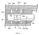
- Fig. 8 is an enlargement view of an arrow indicating part 8 of Fig. 1.
- Fig. 9 is a diagram showing the operation timing of pump plungers.
- Fig. 10 is a diagram showing the operation timing of motor plungers.
- Fig. 11 is a longitudinal sectional view of a hydrostatic type continuously variable transmission according to a second embodiment and a cross-sectional view taken along line 11 - 11 of Fig. 12.
- Fig. 12 is a cross-sectional view of a rotor viewed in the arrow direction of line 12 - 12 of Fig. 11.
- Fig. 13 is a cross-sectional view taken along line 13 - 13 of Fig. 12.
- Figs. 1 to 10 show a first embodiment of the present invention.
- In Fig. 1, in the hydrostatic type continuously variable transmission, a swash plate type fixed displacement hydraulic pump PA as a swash plate type hydraulic drive transmission and a swash plate type variable displacement hydraulic motor MA as another swash plate type hydraulic drive transmission are connected via a low
pressure oil passage 11A and a highpressure oil passage 12A to construct a hydraulic closed circuit. - The hydraulic pump PA has an input
cylindrical shaft 14 provided in its outer circumference with agear 13 to which power from a power source such as engine, not shown, is transmitted, acylinder block 15A arranged coaxially of the inputcylindrical shaft 14 so as to be covered in part, a plurality ofpump plungers 17 ... slidably fitted respectively in a plurality of bottomedpump cylinder holes 16 ... provided in thecylinder block 15A in an annular arrangement so as to surround its rotation axis, and apump swash plate 18 with which the protruding end from thecylinder block 15A of thepump plungers 17 ... is brought into contact and engaged so as to be supported by the inputcylindrical shaft 14. - An angular contact bearing 19 and a ball bearing 20 are interposed between the
pump swash plate 18 and the inputcylindrical shaft 14. Thepump swash plate 18 is relatively, rotatably supported by the inputcylindrical shaft 14 so as to hold a posture tilted at a fixed angle to the axis of thecylinder block 15A. Thepump swash plate 18 can repeat suction and discharge strokes by giving a reciprocating motion to thepump plungers 17 ... when the inputcylindrical shaft 14 is rotated. - The
cylinder block 15A is in common with the hydraulic pump PA and the hydraulic motor MA. Arotor 23A is constructed by thecylinder block 15A, arotation axis 21A coaxially pressed into thecylinder block 15A, and acylindrical member 22A fixed by shrink fit or press fit in the outer circumference of thecylinder block 15A. Therotor 23A is supported in acasing 26 so as to be rotatable about the axis of thecylinder block 15A. - An angular contact bearing 24 is interposed between one end of the
rotation axis 21A and the inputcylindrical shaft 14. An angular contact bearing 25 is interposed between the other end of therotation axis 21A and thecasing 26. A ball bearing 27 is interposed between thecylindrical member 22A and the inputcylindrical shaft 14. A ball bearing 28 is interposed between thecylindrical member 22A and thecasing 26. - The hydraulic motor MA has the
cylinder block 15A, a plurality ofmotor plungers 32 ... slidably fitted respectively in a plurality of bottomedmotor cylinder holes 31 ... provided in thecylinder block 15A in an annular arrangement so as to surround its rotation axis, amotor swash plate 33 with which the protruding end from thecylinder block 15A of themotor plungers 32 ... is brought into contact and engaged, aswash plate holder 34 for supporting themotor swash plate 33 via an angular contact bearing 36 and a ball bearing 37, and aswash plate anchor 35 provided in thecasing 26 so as to support the back surface of theswash plate holder 34. - The number of the
motor cylinder holes 31 ... and themotor plungers 32 ... of the hydraulic motor MA is set to an odd number equal to the number of thepump cylinder holes 16 ... and thepump plungers 17 ... of the hydraulic pump PA, for example, nine. Themotor cylinder holes 31 ... and themotor plungers 32 ..., and thepump cylinder holes 16 ... and thepump plungers 17 ... are arranged to be mutually shifted axially of thecylinder block 15A at the same angular position along the circumferential direction of thecylinder block 15A. -
Opposite contact surfaces swash plate holder 34 and theswash plate anchor 35 are formed in spherical shape centering on the intersecting point of the rotation axis and the trunnion axis O of thecylinder block 15A. Theswash plate holder 34 can be rotated about the trunnion axis O to be supported by theswash plate anchor 35. - A
screw axis 38 having an axis in parallel with therotation axis 21A is rotatably supported in thecasing 26 viaball bearings nut 40 threadedly engaged with thescrew axis 38 is coupled to acoupling arm 34b provided in theswash plate holder 34 via acoupling pin 41 having an axis in parallel with the trunnion axis O. Onto one end portion of thescrew axis 38, agear 39 for transmitting power from a power source, not shown, to thescrew axis 38 is fixed. - The
swash plate holder 34 is rotated about the trunnion axis O corresponding to rotation of thescrew axis 38. Themotor swash plate 33 is operated between an upright position at right angles to the axis of thecylinder block 15A and a maximum tilt position tilted at a certain angle. Themotor swash plate 33 in a tilted state gives a reciprocating motion to themotor plungers 32 ... with rotation of thecylinder block 15A to repeat expansion and reduction strokes. - Referring to Figs. 2 to 5, on the hydraulic pump PA side, the
cylinder block 15A is provided in its outer circumference with first low pressure and high pressureannular recesses cylinder block 15A is provided in its outer circumference with second low pressure and high pressureannular recesses annular recesses 45 to 48 are covered by thecylindrical member 22A. Between thepump cylinder holes 16 ... and themotor cylinder holes 31 ..., thecylinder block 15A is provided with four low pressureside communication passages 49 ... extended in parallel with therotation axis 21A from one end of thecylinder block 15A to a position corresponding to the second low pressureannular recess 47. Between thepump cylinder holes 16 ... and themotor cylinder holes 31 ..., in remaining five positions not provided with the low pressureside communication passages 49 ..., thecylinder block 15A is provided with high pressureside communication passages 50 ... extended in parallel with therotation axis 21A from one end of thecylinder block 15A to the second high pressureannular recess 48. - One end of the low pressure
side communication passages 49 ... is closed in liquid-tight manner bylow pressure plugs 51 ... pressed into thecylinder block 15A. Thelow pressure plugs 51 ... are formed in a bottomed cylindrical shape so as to allow the first low pressureannular recess 45 to be communicated to the low pressureside communication passages 49 ... and to block communication of the first high pressureannular recess 46 to the low pressureside communication passages 49 .... The second low pressureannular recess 47 is communicated to the inner end of the low pressureside communication passages 49 .... - One end of the high pressure
side communication passages 50 ... is closed in liquid-tight manner by high pressure plugs 52 ... pressed into thecylinder block 15A. The high pressure plugs 52 ... are formed to block communication of the first low pressureannular recess 45 to the high pressureside communication passages 50 .... The first and second high pressureannular recesses side communication passages 50 .... The depth of the second low pressureannular recess 47 is set so as not to be communicated to the high pressureside communications passages 50 .... - The low
pressure oil passage 11A has the first low pressureannular recess 45, the low pressureside communication passages 49 ..., and the second low pressureannular recess 47. The highpressure oil passage 12A has the first high pressureannular recess 46, the high pressureside communication passages 50 ..., and the second high pressureannular recess 48. - In a portion to arrange the low pressure plugs 51 ..., the
cylinder block 15A is provided with low pressureside supply passages 54 ... to allow a firstannular passage 53 formed between thecylinder block 15A and therotation axis 21A to be communicated to the first low pressureannular recess 45 so as to extend in the radius direction of thecylinder block 15A. In a portion to arrange the high pressure plugs 52 ..., thecylinder block 15A is provided with high pressure side supply passages 56 ... to allow a secondannular passage 55 formed between thecylinder block 15A and therotation axis 21A to be communicated to the high pressureside communication passages 50 ... so as to extend in the radius direction of thecylinder block 15A. The outer end of the high pressure side supply passages 56 ... is closed by thecylindrical member 22A. - The
rotation axis 21A is provided coaxially with asupply oil passage 59 to which working fluid is supplied from a pump, not shown. Acheck valve 57 interposed between thesupply oil passage 59 and the firstannular passage 53 and acheck valve 58 interposed between thesupply oil passage 59 and the secondannular passage 55 are mounted in the outer circumference portion of therotation axis 21A. - In the hydraulic pump PA, pump
oil chambers 61 ... are formed between the closed end of the pump cylinder holes 16 ... and thepump plungers 17 .... In the hydraulic motor MA,motor oil chambers 62 ... are formed between the closed end of the motor cylinder holes 31 ... and themotor plungers 32 .... - A plurality of first distributing
valves 63A ... which allow thepump oil chambers 61 ... of thepump plungers 17 ... in a suction region to be communicated to the lowpressure oil passage 11A and which allow thepump oil chambers 61 ... of thepump plungers 17 ... in a discharge region to be communicated to the highpressure oil passage 12A are provided corresponding to thepump plungers 17 ... between the lowpressure oil passage 11A and the highpressure oil passage 12A and thepump oil chambers 61 .... A plurality of second distributingvalves 64A ... which allow themotor oil chambers 62 ... of themotor plungers 32 ... in an expansion region to be communicated to the highpressure oil passage 12A and which allow themotor oil chambers 62 ... of themotor plungers 32 ... in a reduction region to be communicated to the lowpressure oil passage 11A are provided corresponding to themotor plungers 32 ... between the lowpressure oil passage 11A and the highpressure oil passage 12A and themotor oil chambers 62 .... - In Fig. 6, the first distributing
valves 63A ... alternately switch, corresponding to the axial reciprocating motion of thepump plungers 17 ..., communication and cutoff between a plurality of pumpside communication passages 65A ... communicated to thepump oil chambers 61 ... opening to the inner surface of the pump cylinder holes 16 ... and a plurality of first low pressure and high pressure ports 66A ... and 67A ... respectively communicated to the lowpressure oil passage 11A and the highpressure oil passage 12A opening to the inner surface of the pump cylinder holes 16 .... - The first low pressure ports 66A ... extend inwardly in the radius direction of the
cylinder block 15A from the first low pressureannular recess 45 in the lowpressure oil passage 11A to be opened to the inner surface of the pump cylinder holes 16 .... The first high pressure ports 67A ... extend inwardly in the radius direction of thecylinder block 15A from the first highpressureannular recess 46 in the highpressure oil passage 12A to be opened to the inner surface of the pump cylinder holes 16 .... - The pump
side communication passages 65A ... have pumpside communication grooves 68A ... provided in the outer circumference surface of therotation axis 21A,passages 69A ... radially drilled in thecylinder block 15A so as to allow one end of the pumpside communication grooves 68A ... to be respectively communicated to thepump oil chambers 61 ..., andpassages 70A ... radially drilled in thecylinder block 15A between the first low pressure and high pressure ports 66A ... and 67A ... to be communicated to the other end of the pumpside communication grooves 68A ... opening to the inner surface of the pump cylinder holes 16 .... The outer end of thepassages 69A ... and 70A ... is closed by thecylindrical member 22A. - In Fig. 7, the pump
side communication grooves 68A ... are formed helically so that with respect to the position of thepassages 69A ... communicated to one end thereof, the position of thepassages 70A ... communicated to the other end is shifted in the reverse direction, for example, 80° to arotating direction 71 of therotation axis 21A and thecylinder block 15A and are formed in the outer circumference surface of therotation axis 21A by rolling. - The other end of the pump
side communication passage 65A whose one end is communicated to thepump oil chamber 61 is arranged in the inner surface of thepump cylinder hole 16 shifted in the reverse direction, for example, 80° to therotating direction 71 of therotation axis 21A and thecylinder block 15A so as to be opened in the middle portion between the first low pressure port 66A and the first high pressure port 67A. In the outer circumference of the middle portion axially of thepump plungers 17 ...,annular recesses 72 ... for switching communication and cutoff between the pumpside communication passages 65A ... and the first low pressure and high pressure ports 66A ... and 67A ... are provided. - In Fig. 8, the second distributing
valves 64A ... alternately switch, corresponding to the axial reciprocating motion of themotor plungers 32 ..., communication and cutoff between motorside communication passages 75A ... communicated to themotor oil chambers 62 ... opening to the inner surface of the motor cylinder holes 31 ... and second low pressure and high pressure ports 76A ... and 77A ... respectively communicated to the lowpressure oil passage 11A and the highpressure oil passage 12A opening to the inner surface of the motor cylinder holes 31 .... - The second low pressure ports 76A ... are formed to be opened to the inner surface of the motor cylinder holes 31 ... so that the motor cylinder holes 31 ... are across part of the second low pressure
annular recess 47 in the lowpressure oil passage 11A. The second high pressure ports 77A ... are formed to be opened to the inner surface of the motor cylinder holes 31 ... so that the motor cylinder holes 31 ... are across part of the second high pressureannular recess 48 in the highpressure oil passage 12A. - The motor
side communication passages 75A ... have motorside communication grooves 78A ... provided in the outer circumference surface of therotation axis 21A,passages 79A ... radially drilled in thecylinder block 15A so as to allow one end of the motorside communication grooves 78A ... to be communicated to themotor oil chambers 62 ..., andpassages 80A ... radially drilled in thecylinder block 15A between the second low pressure and high pressure ports 76A ... and 77A ... to be communicated to the other end of the motorside communication grooves 78A ... opening to the inner surface of the motor cylinder holes 31 .... The outer end of thepassages 79A ... and 80A ... is closed by thecylindrical member 22A. - In Fig. 7, the motor
side communication grooves 78A ... are formed helically so that with respect to the position of thepassages 79A ... communicated to one end thereof, the position of thepassages 80A ... communicated to the other end is shifted in the reverse direction, for example, 80° to therotating direction 71 of therotation axis 21A and thecylinder block 15A and are formed on the outer circumference surface of therotation axis 21A by rolling. - The other end of the motor
side communication passage 75A whose one end is communicated to themotor oil chamber 62 is arranged in the inner surface of themotor cylinder hole 31 shifted in the reverse direction, for example, 80° to therotating direction 71 of therotation axis 21A and thecylinder block 15A so as to be opened in the middle portion between the second low pressure port 76A and the second high pressure port 77A. In the outer circumference of the middle portion axially of themotor plungers 32 ...,annular recesses 82 ... for switching communication and cutoff between the motorside communication passages 75A ... and the second low pressure and high pressure ports 76A ... and 77A ... are provided. - The operation of the first embodiment will be described. While the
motor swash plate 33 is held at a tilt angle, engine power, not shown, is transmitted to the inputcylindrical shaft 14 of the hydraulic pump PA. Thepump swash plate 18 supported by the inputcylindrical shaft 14 gives a reciprocating motion to thepump plungers 17 .... - As shown in Fig. 9, while the
pump plungers 17 ... pass through the discharge region D to reduce the volume of thepump oil chambers 61 ... , the first distributingvalves 63A ... allow thepump oil chambers 61 ... to be communicated to the highpressure oil passage 12A. The working fluid from thepump oil chambers 61 ... is discharged to the highpressure oil passage 12A. While thepump plungers 17 ... pass through the suction region S to expand the volume of thepump oil chambers 61 ..., the first distributingvalves 63A ... allow thepump oil chambers 61 ... to be communicated to the lowpressure oil passage 11A. The working fluid from the lowpressure oil passage 11A is suctioned into thepump oil chamber 61 .... - In the hydraulic motor MA, as shown in Fig. 10, while the
motor plungers 32 ... are present in the expansion region E to expand the volume of themotor oil chambers 62 ..., the second distributingvalves 64A ... allow themotor oil chambers 62 ... to be communicated to the highpressure oil passage 12A, and while themotor plungers 32 ... are present in the reduction region R to reduce the volume of themotor oil chambers 62 ... , the second distributingvalves 64A ... allow themotor oil chambers 62 ... to be communicated to the lowpressure oil passage 11A. For this reason, the high pressure working fluid discharged from thepump oil chambers 61 ... of the hydraulic pump PA to the highpressure oil passage 12A is supplied to themotor oil chambers 62 ... of themotor plungers 32 ... present in the expansion region E to give a thrust force to themotor plungers 32 .... Themotor plungers 32 ... present in the reduction region R discharges the working fluid from themotor oil chambers 62 ... to the lowpressure oil passage 11A corresponding to the proceeding of the reduction stroke. - The
motor plungers 32 ... receiving the thrust force by the high pressure working fluid of themotor oil chambers 62 are pressed against themotor swash plate 33 to exert rotating torque. Therotor 23A including thecylinder block 15A is rotated in the same direction as that of the inputcylindrical shaft 14 by the reaction torque. The rotating torque of therotor 23A is transmitted from therotation axis 21A to a load, not shown. - The hydraulic pump PA is of a fixed displacement type. The hydraulic motor MA is of a variable displacement type which varies the tilt angle of the
motor swash plate 33. The tilt angle of themotor swash plate 33 is varied to increase and decrease the displacement of the hydraulic motor MA. The gear ratio between the inputcylindrical shaft 14 and therotation axis 21A can be varied continuously. - Such a hydrostatic type continuously variable transmission has the first distributing
valves 63A ... which switch, by the reciprocatively operatedpump plungers 17 ..., communication and cutoff between the pump side communication passages 65 ... communicated to thepump oil chambers 61 ... and the first low pressure and high pressure ports 66A ... and 67A ... respectively communicated to the lowpressure oil passage 11A and the highpressure oil passage 12A, and the second distributingvalves 64A which switch, by the reciprocatively operatedmotor plungers 32 ..., communication and cutoff between the motorside communication passages 75A communicated to themotor oil chambers 62 ... and the second low pressure and high pressure ports 76A ... and 77A ... respectively communicated to the lowpressure oil passage 11A and the highpressure oil passage 12A. - The sliding holes only for the first and second distributing
valves 63A ... and 64A ... need not be provided in thecylinder block 15A. Thecylinder block 15A can be made smaller according to the unrequired sliding holes and the number of processes can be reduced. The parts only for the first and second distributingvalves 63A ... and 64A ... are unnecessary to reduce the number of parts. - Part of the pump
side communication passages 65A ... and part of the motorside communication passages 75A ... are constructed by the pump side and motorside communication grooves 68A ... and 78A ... provided in the outer circumference of therotation axis 21A coaxially pressed into thecylinder block 15A. The pumpside communication grooves 68A ... and the motorside communication grooves 78A ... are easily formed in the outer circumference surface of therotation axis 21A. The number of processes can be further reduced. - The
cylindrical member 22A is fixed by shrink fit or press fit in the outer circumference of thecylinder block 15A. Brazing is unnecessary to contribute to reduction of the manufacturing cost. - The
cylindrical member 22A seals the outer end opening portion of the first and second low pressureannular recesses pressure oil passage 11A and the first and second high pressureannular recesses pressure oil passage 12A. A shrink fit portion or a press fit portion between thecylindrical member 22A and thecylinder block 15A is correctly determined. When the oil pressure of the lowpressure oil passage 11A or the highpressure oil passage 12A is excessive, the working fluid is released from between thecylinder block 15A and thecylindrical member 22A. Thecylindrical member 22A can serve as the function of a pressure limiter. No pressure-regulating valves are thus required. - Fig. 11 is a longitudinal sectional view of a hydrostatic type continuously variable transmission of a second embodiment of the present invention and is a cross-sectional view taken along line 11 - 11 of Fig. 12. Fig. 12 is a cross-sectional view of a rotor viewed in the arrow direction of line 12 - 12 of Fig. 11. Fig. 13 is a cross-sectional view taken along line 13 - 13 of Fig. 12. Parts corresponding to the first embodiment are indicated by the same reference numerals, and the detailed description thereof is omitted.
- In the hydrostatic type continuously variable transmission, a swash plate type fixed displacement hydraulic pump PB and a swash plate type variable displacement hydraulic motor MB are connected via a low
pressure oil passage 11B and a highpressure oil passage 12B to construct a hydraulic closed circuit. - A
rotor 23B is constructed by thecylinder block 15B in common with the hydraulic pump PB and the hydraulic motor MB, arotation axis 21B coaxially pressed into thecylinder block 15B, and acylindrical member 22B fixed by shrink fit or press fit in the outer circumference of thecylinder block 15B. Therotor 23B is supported in acasing 26 so as to be rotatable about the axis of thecylinder block 15B and therotation axis 21B. - The hydraulic pump PB has a plurality of, for example, nine
pump plungers 17 .... The pump plungers 17 ... are slidably fitted respectively in bottomed pump cylinder holes 16 ... provided in an annular arrangement in a portion inwardly in the radius direction of thecylinder block 15B. The outer end of thepump plungers 17 ... is brought into contact with and engaged with apump swash plate 18. - The hydraulic motor MB has a plurality of, for example, nine
motor plungers 32 .... Themotor plungers 32 ... are slidably fitted respectively in bottomed motor cylinder holes 31 provided in an annular arrangement in a portion outwardly in the radius direction of thecylinder block 15B. The outer end of themotor plungers 32 ... is brought into contact with and engaged with amotor swash plate 33. The motor cylinder holes 31 ... are mutually arranged between the pump cylinder holes 16 ... along the circumferential direction of thecylinder block 15B. - In the
rotor 23B, the annular lowpressure oil passage 11B and the annular highpressure oil passage 12B are formed in positions spaced along the axial direction of therotor 23B. - Between the outer circumference of the
cylinder block 15B and thecover 22B, a low pressureside supply passage 84 extending in parallel with therotation axis 21B is provided so that its one end is communicated to the lowpressure oil passage 11B. The other end of the low pressureside supply passage 84 is communicated to a low pressureside supply passage 86 provided in thecylinder block 15B so as to extend in the radius direction of thecylinder block 15B. In thecylinder block 15B, a high pressureside supply passage 87 having one end thereof opened in the inner circumference of thecylinder block 15B and the other end communicated to the highpressure oil passage 12B. - On the
rotation axis 21B are mounted acheck valve 57 interposed between asupply oil passage 59 in therotation axis 21B and the low pressureside supply passage 86 and acheck valve 58 interposed between thesupply oil passage 59 and the high pressureside supply passage 87. - A plurality of first distributing
valves 63B which allowpump oil chambers 61 ... of thepump plungers 17 ... in the suction region to be communicated to the lowpressure oil passage 11B and which allow thepump oil chambers 61 ... of thepump plungers 17 ... in the discharge region to be communicated to the highpressure oil passage 12B are provided corresponding to thepump plungers 17 ... between the lowpressure oil passage 11B and the highpressure oil passage 12B and thepump oil chambers 61 ... formed between the closed end of the pump cylinder holes 16 ... and thepump plungers 17 .... A plurality of second distributingvalves 64B which allowmotor oil chambers 62 ... of themotor plungers 32 ... in the expansion region to be communicated to the highpressure oil passage 12B and which allow themotor oil chambers 62 ... of themotor plungers 32 ... in the reduction region to be communicated to the lowpressure oil passage 11B are provided corresponding to thepump plungers 32 ... between the lowpressure oil passage 11B and the highpressure oil passage 12B and themotor oil chambers 62 ... formed between the closed end of the motor cylinder holes 31 ... and themotor plungers 32 .... - The first distributing
valves 63B ... alternately switch, corresponding to the axial reciprocating motion of thepump plungers 17 ... each having anannular recess 72, communication and cutoff between a plurality of pumpside communication passages 65B ... communicated to thepump oil chambers 61 ... opening to the inner surface of the pump cylinder holes 16 ... and a plurality of first low pressure andhigh pressure ports 66B ... and 67B ... respectively communicated to the lowpressure oil passage 11B and the highpressure oil passage 12B opening to the inner surface of the pump cylinder holes 16 .... - The first
low pressure ports 66B ... are formed so as to be opened to the inner surface of the pump cylinder holes 16 ... so that the pump cylinder holes 16 ... are across the lowpressure oil passage 11B. The firsthigh pressure ports 67B ... are formed so as to be opened to the inner surface of the pump cylinder holes 16 ... so that the pump cylinder holes 16 ... are across the highpressure oil passage 12B. - The pump
side communication passages 65B ... have pumpside communication grooves 68B ... provided in the outer circumference surface of therotation axis 21B,passages 69B ... radially drilled in thecylinder block 15B so as to allow one end of the pumpside communication grooves 68B ... to be respectively communicated to thepump oil chambers 61 ..., andpassages 70B ... radially drilled in thecylinder block 15B between the first low pressure andhigh pressure ports 66B ... and 67B ... to be communicated to the other end of the pumpside communication grooves 68B ... opening to the inner surface of the pump cylinder holes 16 .... - The pump
side communication grooves 68B ... are formed helically as in the first embodiment and are formed in the outer circumference surface of therotation axis 21B by rolling. - The second distributing
valves 64B ... alternately switch, corresponding to the axial reciprocating motion of themotor plungers 32 ... each having anannular recess 82, communication and cutoff between motor side communication passages 75B ... communicated to themotor oil chambers 62 ... opening to the inner surface of the motor cylinder holes 31 ... and second low pressure andhigh pressure ports 76B ... and 77B ... respectively communicated to the lowpressure oil passage 11B and the highpressure oil passage 12B opening to the inner surface of the motor cylinder holes 31 .... - The second
low pressure ports 76B ... are formed so as to be opened to the inner surface of the motor cylinder holes 31 ... so that the motor cylinder holes 31 ... are across the lowpressure oil passage 11B. The secondhigh pressure ports 77B ... are formed so as to be opened to the inner surface of the motor cylinder holes 31 ... so that the motor cylinder holes 31 ... are across the highpressure oil passage 12B. - The motor side communication passages 75B ... have motor side communication grooves 78B ... provided in the outer circumference surface of the
cylinder block 15B, passages 79B ... radially drilled in thecylinder block 15B so as to allow one end of the motor side communication grooves 78B ... to be respectively communicated to themotor oil chambers 62 ..., andpassages 80B ... radially drilled in thecylinder block 15B between the second low pressure andhigh pressure ports 76B ... and 77B ... to be communicated to the other end of the motor side communication grooves 78B ... opening to the inner surface of the motor cylinder holes 31 .... - The motor side communication grooves 78B ... are formed helically as in the first embodiment and are formed in the outer circumference surface of the
rotation axis 21B by rolling. - The second embodiment can provide the same effect as the first embodiment and make the
cylinder block 15B smaller. The sliding holes only for the first and second distributingvalves 63B ... and 64B ... need not be provided in thecylinder block 15B. The diameter of thecylinder block 15B is prevented from being increased. The pump plungers 17 ... and themotor plungers 32 ... can be in an annular arrangement to be shifted in the circumferential direction and the radius direction of thecylinder block 15B. The axial length of thecylinder block 15B can be reduced. - The invention can be summarized as follows:
- Distributing valves of a swash plate type hydraulic drive transmission can make a cylinder block smaller and reduce the number of processes and the number of parts.
- Distributing
valves 63A alternately switch, corresponding to the axial reciprocating motion ofplungers 17, communication and cutoff betweencommunication passages 65A communicated tooil chambers 61 opening to the inner surface of cylinder holes 16 and low pressure ports 66A and high pressure ports 67A communicated to a lowpressure oil passage 11A and a highpressure oil passage 12A opening to the inner surface of the cylinder holes 16. -
Claims (3)
- A swash plate type hydraulic drive transmission in which rotors (23A, 23B) including cylinder blocks (15A, 15B) are supported in a casing (26) so as to be rotatable about the axis of said cylinder blocks (15A, 15B), plungers (17, 32) whose outer end is brought into contact with and engaged with swash plates (18, 33) to form oil chambers (61, 62) between the plungers (17, 32) and the closed ends of cylinder holes (16, 17) are slidably fitted in a plurality of said bottomed cylinder holes (16, 31) provided in said cylinder blocks (15A, 15B) in an annular arrangement, and distributing valves (63A, 63B; 64A, 64B) which allow the oil chambers (61, 62) of the plungers (17, 32) moving to a side for expanding said oil chambers (61, 62) to be communicated to low pressure oil passages (11A, 11B) and which allow the oil chambers (61, 62) of the plungers (17, 32) moving to a side for reducing said oil chambers (61, 62) to be communicated to high pressure oil passages (12A, 12B) are provided corresponding to the plungers (17, 32) between the low pressure oil passages (11A, 11B) and the high pressure oil passages (12A, 12B) provided in said rotors (23A, 23B) and said oil chambers (61, 62), wherein the distributing valves (63A, 63B: 64A, 64B) alternately switch, corresponding to the axial reciprocating motion of the plungers (17, 32), communication and cutoff between a plurality of communication passages (65A, 65B: 75A, 75B) communicated to said oil chambers (61, 62) opening to the inner surface of the cylinder holes (16, 31) and a plurality of low pressure and high pressure ports (66A, 66B, 76A, 76B; 67A, 67B, 76A, 76B) respectively communicated to said low pressure oil passages (11A, 11B) and said high pressure oil passages (12A, 12B) opening to the inner surface of the cylinder holes (16, 31).
- A hydrostatic type continuously variable transmission in which rotors (23A, 23B) including cylinder blocks (15A, 15B) in common with hydraulic pumps (PA, PB) and hydraulic motors (MA, MB) are supported in a casing (26) so as to be rotatable about the axis of said cylinder blocks (15A, 15B), a plurality of pump plungers (17) provided in the hydraulic pumps (PA, PB) to form pump oil chambers (61) between the pump plungers (17) and the closed end of pump cylinder holes (16) are slidably fitted in the bottomed cylinder holes (16) provided in said cylinder blocks (15A, 15B) in an annular arrangement, a plurality of motor plungers (32) provided in the hydraulic motors (MA, MB) to form motor oil chambers (62) between the motor plungers (32) and the closed end of motor cylinder holes (31) are slidably fitted in the bottomed motor cylinder holes (31) provided in said cylinder blocks (15A, 15B) in an annular arrangement, a plurality of first distributing valves (63A, 63B) which allow the pump oil chambers (61) of the pump plungers (17) in a suction region (S) to be communicated to low pressure oil passages (11A, 11B) and which allow the pump oil chambers (61) of the pump plungers (17) in a discharge region (D) to be communicated to high pressure oil passages (12A, 12B) are provided corresponding to the pump plungers (17) between the low pressure oil passages (11A, 11B) and the high pressure oil passages (12A, 12B) provided in said rotors (23A, 23B) and said pump oil chambers (61), and a plurality of second distributing valves (64A, 64B) which allow the motor oil chambers (62) of the motor plungers (32) in an expansion region (E) to be communicated to the high pressure oil passages (12A, 12B) and which allow the motor oil chambers (62) of the motor plungers (32) in a reduction region (R) to be communicated to the low pressure oil passages (11A, 11B) are provided corresponding to the motor plungers (32) between said low pressure oil passages (11A, 11B) and said high pressure oil passages (12A, 12B) and said motor oil chambers (62), wherein the first distributing valves (63A, 63B) alternately switch, corresponding to the axial reciprocating motion of the pump plungers (17), communication and cutoff between a plurality of pump side communication passages (65A, 65B) communicated to the pump oil chambers (61) opening to the inner surface of the pump cylinder holes (16) and a plurality of first low pressure and high pressure ports (66A, 66B; 67A, 67B) respectively communicated to said low pressure oil passages (11A, 11B) and said high pressure oil passages (12A, 12B) opening to the inner surface of the pump cylinder holes (16), and the second distributing valves (64A, 64B) alternately switch, corresponding to the axial reciprocating motion of the motor plungers (32), communication and cutoff between a plurality of motor side communication passages (75A, 75B) communicated to the motor oil chambers (62) opening to the inner surface of the motor cylinder holes (31) and a plurality of second low pressure and high pressure ports (76A, 76B; 77A, 77B) respectively communicated to said low pressure oil passages (11A, 11B) and said high pressure oil passages (12A, 12B) opening to the inner surface of the motor cylinder holes (31).
- The hydrostatic type continuously variation transmission according to claim 2, wherein said rotor (23A) includes said cylinder block (15A) and a rotation axis (21A) coaxially pressed into the cylinder block (15A), a plurality of said pump side communication passages (65A) are in part constructed by a plurality of pump side communication grooves (68A, 68B) provided in the outer circumference surface of said rotation axis (21A), and a plurality of said motor side communication passages (75A) are in part constructed by a plurality of motor side communication grooves (78A, 78B) provided in the outer circumference surface of said rotation axis (21A).
Applications Claiming Priority (2)
| Application Number | Priority Date | Filing Date | Title |
|---|---|---|---|
| JP2001110422 | 2001-04-09 | ||
| JP2001110422A JP3986764B2 (en) | 2001-04-09 | 2001-04-09 | Hydrostatic continuously variable transmission |
Publications (3)
| Publication Number | Publication Date |
|---|---|
| EP1249640A2 true EP1249640A2 (en) | 2002-10-16 |
| EP1249640A3 EP1249640A3 (en) | 2005-01-19 |
| EP1249640B1 EP1249640B1 (en) | 2006-07-12 |
Family
ID=18962193
Family Applications (1)
| Application Number | Title | Priority Date | Filing Date |
|---|---|---|---|
| EP02006411A Expired - Lifetime EP1249640B1 (en) | 2001-04-09 | 2002-03-21 | Swash plate type hydraulic transmission |
Country Status (10)
| Country | Link |
|---|---|
| US (1) | US6698199B2 (en) |
| EP (1) | EP1249640B1 (en) |
| JP (1) | JP3986764B2 (en) |
| CN (1) | CN1270105C (en) |
| AT (1) | ATE333060T1 (en) |
| BR (1) | BR0201105B1 (en) |
| CA (1) | CA2378021C (en) |
| DE (1) | DE60213021T8 (en) |
| MY (1) | MY134832A (en) |
| PT (1) | PT1249640E (en) |
Families Citing this family (13)
| Publication number | Priority date | Publication date | Assignee | Title |
|---|---|---|---|---|
| JP2004019836A (en) * | 2002-06-18 | 2004-01-22 | Yanmar Co Ltd | Hydraulic continuously variable transmission and power transmission apparatus |
| JP4139720B2 (en) * | 2003-03-31 | 2008-08-27 | 本田技研工業株式会社 | Swash plate plunger hydraulic unit |
| JP4174364B2 (en) | 2003-04-21 | 2008-10-29 | 本田技研工業株式会社 | Power unit |
| JP2005256977A (en) * | 2004-03-12 | 2005-09-22 | Honda Motor Co Ltd | Hydrostatic continuously-variable-transmission (cvt) |
| DE102005010015B4 (en) * | 2004-03-12 | 2013-07-04 | Honda Motor Co., Ltd. | Coupling device for a hydrostatic continuously variable transmission |
| US8056333B1 (en) | 2007-08-01 | 2011-11-15 | Hydro-Gear Limited Partnership | Pump and engine configuration |
| US8925311B1 (en) | 2009-07-24 | 2015-01-06 | Hydro-Gear Limited Partnership | Transmission and engine configuration |
| CN101975260B (en) * | 2010-11-02 | 2013-01-23 | 北京联合大学 | Swash plate type impulse stepless gear box with continuously adjustable speed ratio |
| JP6106834B2 (en) * | 2012-08-28 | 2017-04-05 | ダイハツ工業株式会社 | Hydraulic continuously variable transmission |
| JP6106833B2 (en) * | 2012-08-28 | 2017-04-05 | ダイハツ工業株式会社 | Hydraulic continuously variable transmission |
| CN104948408B (en) * | 2015-07-01 | 2017-06-30 | 张意 | A kind of axial variable displacement plunger pump |
| EP3562377B1 (en) | 2016-12-27 | 2023-09-20 | DePuy Synthes Products, Inc. | Systems, methods, and devices for providing illumination in an endoscopic imaging environment |
| CN116025533B (en) * | 2022-11-24 | 2023-08-08 | 温州锐劲动力机械有限公司 | Axial plunger pump with axial flow distribution and rolling support |
Citations (4)
| Publication number | Priority date | Publication date | Assignee | Title |
|---|---|---|---|---|
| GB856258A (en) * | 1957-10-10 | 1960-12-14 | British Hydromechanics | Improvements in or relating to hydraulic power transmission systems |
| DE1919510A1 (en) * | 1969-04-17 | 1970-10-29 | Friedhelm Schwarz | Axial piston unit |
| US5205123A (en) * | 1990-09-06 | 1993-04-27 | Dunstan Phillip E | Infinitely variable differential hydrostatic transmission |
| EP0902212A2 (en) * | 1997-09-11 | 1999-03-17 | Honda Giken Kogyo Kabushiki Kaisha | Swash plate type continuously variable transmission |
Family Cites Families (5)
| Publication number | Priority date | Publication date | Assignee | Title |
|---|---|---|---|---|
| GB504554A (en) * | 1937-09-22 | 1939-04-24 | Hans Joseph Zimmermann | Improvements in and connected with reciprocating pumps, applicable also for motors |
| US2391575A (en) * | 1943-01-07 | 1945-12-25 | New York Air Brake Co | Reversible engine |
| US2923251A (en) * | 1956-04-02 | 1960-02-02 | New York Air Brake Co | Rotary engine |
| JP3923147B2 (en) | 1997-09-11 | 2007-05-30 | 本田技研工業株式会社 | Swash plate hydraulic system |
| JP3974998B2 (en) * | 1998-03-31 | 2007-09-12 | 本田技研工業株式会社 | Hydraulic mechanical continuously variable transmission for vehicles |
-
2001
- 2001-04-09 JP JP2001110422A patent/JP3986764B2/en not_active Expired - Fee Related
-
2002
- 2002-03-21 CA CA002378021A patent/CA2378021C/en not_active Expired - Fee Related
- 2002-03-21 EP EP02006411A patent/EP1249640B1/en not_active Expired - Lifetime
- 2002-03-21 DE DE60213021T patent/DE60213021T8/en not_active Expired - Fee Related
- 2002-03-21 AT AT02006411T patent/ATE333060T1/en not_active IP Right Cessation
- 2002-03-21 PT PT02006411T patent/PT1249640E/en unknown
- 2002-03-22 CN CNB021192944A patent/CN1270105C/en not_active Expired - Fee Related
- 2002-04-02 US US10/112,877 patent/US6698199B2/en not_active Expired - Fee Related
- 2002-04-02 MY MYPI20021199A patent/MY134832A/en unknown
- 2002-04-02 BR BRPI0201105-0A patent/BR0201105B1/en not_active IP Right Cessation
Patent Citations (4)
| Publication number | Priority date | Publication date | Assignee | Title |
|---|---|---|---|---|
| GB856258A (en) * | 1957-10-10 | 1960-12-14 | British Hydromechanics | Improvements in or relating to hydraulic power transmission systems |
| DE1919510A1 (en) * | 1969-04-17 | 1970-10-29 | Friedhelm Schwarz | Axial piston unit |
| US5205123A (en) * | 1990-09-06 | 1993-04-27 | Dunstan Phillip E | Infinitely variable differential hydrostatic transmission |
| EP0902212A2 (en) * | 1997-09-11 | 1999-03-17 | Honda Giken Kogyo Kabushiki Kaisha | Swash plate type continuously variable transmission |
Also Published As
| Publication number | Publication date |
|---|---|
| US6698199B2 (en) | 2004-03-02 |
| JP2002310061A (en) | 2002-10-23 |
| DE60213021T8 (en) | 2007-04-05 |
| CN1270105C (en) | 2006-08-16 |
| CA2378021A1 (en) | 2002-10-09 |
| BR0201105B1 (en) | 2010-06-01 |
| EP1249640A3 (en) | 2005-01-19 |
| ATE333060T1 (en) | 2006-08-15 |
| CA2378021C (en) | 2005-05-24 |
| PT1249640E (en) | 2006-12-29 |
| CN1380496A (en) | 2002-11-20 |
| EP1249640B1 (en) | 2006-07-12 |
| DE60213021D1 (en) | 2006-08-24 |
| MY134832A (en) | 2007-12-31 |
| BR0201105A (en) | 2003-05-27 |
| DE60213021T2 (en) | 2006-11-16 |
| JP3986764B2 (en) | 2007-10-03 |
| US20020170289A1 (en) | 2002-11-21 |
Similar Documents
| Publication | Publication Date | Title |
|---|---|---|
| EP1249640B1 (en) | Swash plate type hydraulic transmission | |
| US3175510A (en) | Variable displacement pump | |
| KR100297208B1 (en) | Fluid pressure generator | |
| EP0279695B1 (en) | Hydrostatically operated continuously variable transmission | |
| JPS61153057A (en) | Static hydraulic type continuously variable transmission | |
| US8235681B2 (en) | Opposing swash plate piston pump/motor | |
| US20060120884A1 (en) | Hydrostatic stepless transmission | |
| JPH0321754B2 (en) | ||
| CA2348197C (en) | Hydrostatic continuously variable transmission | |
| US6368072B1 (en) | Hydraulic pump | |
| US10066484B2 (en) | Fluid pressure rotating machine | |
| JP3853932B2 (en) | Swash plate type continuously variable transmission | |
| JP3778370B2 (en) | Structure of pressurized fluid motor | |
| JP3079230B2 (en) | Swash plate type hydraulic device | |
| JP2003014111A (en) | Hydraulic continuously variable transmission and transmission system | |
| JPH09184478A (en) | Multiple pump | |
| US6612222B2 (en) | Hydrostatic continuously variable transmission | |
| KR100474258B1 (en) | Swash Plate Type Axial Piston Pump | |
| JP3696382B2 (en) | Swash plate type continuously variable transmission | |
| JPH0212307B2 (en) | ||
| JP2528999B2 (en) | Rotary fluid energy converter | |
| WO2023188817A1 (en) | Rotary swash plate hydraulic pump | |
| US20020007633A1 (en) | Hydrostatic continuously variable transmission | |
| JPS63203959A (en) | Working oil distributing device for swash type hydraulic device | |
| JPH10288149A (en) | Reciprocating type hydraulic unit and hydraulic type continuously variable transmission |
Legal Events
| Date | Code | Title | Description |
|---|---|---|---|
| PUAI | Public reference made under article 153(3) epc to a published international application that has entered the european phase |
Free format text: ORIGINAL CODE: 0009012 |
|
| AK | Designated contracting states |
Kind code of ref document: A2 Designated state(s): AT BE CH CY DE DK ES FI FR GB GR IE IT LI LU MC NL PT SE TR |
|
| AX | Request for extension of the european patent |
Free format text: AL;LT;LV;MK;RO;SI |
|
| PUAL | Search report despatched |
Free format text: ORIGINAL CODE: 0009013 |
|
| AK | Designated contracting states |
Kind code of ref document: A3 Designated state(s): AT BE CH CY DE DK ES FI FR GB GR IE IT LI LU MC NL PT SE TR |
|
| AX | Request for extension of the european patent |
Extension state: AL LT LV MK RO SI |
|
| 17P | Request for examination filed |
Effective date: 20050609 |
|
| AKX | Designation fees paid |
Designated state(s): AT BE CH CY DE DK ES FI FR GB GR IE IT LI LU MC NL PT SE TR |
|
| GRAP | Despatch of communication of intention to grant a patent |
Free format text: ORIGINAL CODE: EPIDOSNIGR1 |
|
| GRAS | Grant fee paid |
Free format text: ORIGINAL CODE: EPIDOSNIGR3 |
|
| GRAA | (expected) grant |
Free format text: ORIGINAL CODE: 0009210 |
|
| RIN1 | Information on inventor provided before grant (corrected) |
Inventor name: HAYASHI, TSUTOMUC/O K.K. HONDA GIJUTSU KENKYUSHO Inventor name: KANNO, YOSHIHISAC/O K.K. HONDA GIJUTSU KENKYUSHO Inventor name: SAKAKIBARA, KENJIC/O K.K. HONDA GIJUTSU KENKYUSHO Inventor name: YAKIGAYA,NOBUYUKIC/O K.K. HONDA GIJUTSU KENKYUSHO |
|
| AK | Designated contracting states |
Kind code of ref document: B1 Designated state(s): AT BE CH CY DE DK ES FI FR GB GR IE IT LI LU MC NL PT SE TR |
|
| PG25 | Lapsed in a contracting state [announced via postgrant information from national office to epo] |
Ref country code: IT Free format text: LAPSE BECAUSE OF FAILURE TO SUBMIT A TRANSLATION OF THE DESCRIPTION OR TO PAY THE FEE WITHIN THE PRESCRIBED TIME-LIMIT;WARNING: LAPSES OF ITALIAN PATENTS WITH EFFECTIVE DATE BEFORE 2007 MAY HAVE OCCURRED AT ANY TIME BEFORE 2007. THE CORRECT EFFECTIVE DATE MAY BE DIFFERENT FROM THE ONE RECORDED. Effective date: 20060712 Ref country code: LI Free format text: LAPSE BECAUSE OF FAILURE TO SUBMIT A TRANSLATION OF THE DESCRIPTION OR TO PAY THE FEE WITHIN THE PRESCRIBED TIME-LIMIT Effective date: 20060712 Ref country code: AT Free format text: LAPSE BECAUSE OF FAILURE TO SUBMIT A TRANSLATION OF THE DESCRIPTION OR TO PAY THE FEE WITHIN THE PRESCRIBED TIME-LIMIT Effective date: 20060712 Ref country code: NL Free format text: LAPSE BECAUSE OF FAILURE TO SUBMIT A TRANSLATION OF THE DESCRIPTION OR TO PAY THE FEE WITHIN THE PRESCRIBED TIME-LIMIT Effective date: 20060712 Ref country code: CH Free format text: LAPSE BECAUSE OF FAILURE TO SUBMIT A TRANSLATION OF THE DESCRIPTION OR TO PAY THE FEE WITHIN THE PRESCRIBED TIME-LIMIT Effective date: 20060712 Ref country code: BE Free format text: LAPSE BECAUSE OF FAILURE TO SUBMIT A TRANSLATION OF THE DESCRIPTION OR TO PAY THE FEE WITHIN THE PRESCRIBED TIME-LIMIT Effective date: 20060712 |
|
| REG | Reference to a national code |
Ref country code: GB Ref legal event code: FG4D |
|
| REG | Reference to a national code |
Ref country code: CH Ref legal event code: EP |
|
| REG | Reference to a national code |
Ref country code: IE Ref legal event code: FG4D |
|
| REF | Corresponds to: |
Ref document number: 60213021 Country of ref document: DE Date of ref document: 20060824 Kind code of ref document: P |
|
| PG25 | Lapsed in a contracting state [announced via postgrant information from national office to epo] |
Ref country code: DK Free format text: LAPSE BECAUSE OF FAILURE TO SUBMIT A TRANSLATION OF THE DESCRIPTION OR TO PAY THE FEE WITHIN THE PRESCRIBED TIME-LIMIT Effective date: 20061012 |
|
| PG25 | Lapsed in a contracting state [announced via postgrant information from national office to epo] |
Ref country code: ES Free format text: LAPSE BECAUSE OF FAILURE TO SUBMIT A TRANSLATION OF THE DESCRIPTION OR TO PAY THE FEE WITHIN THE PRESCRIBED TIME-LIMIT Effective date: 20061023 |
|
| REG | Reference to a national code |
Ref country code: SE Ref legal event code: TRGR |
|
| REG | Reference to a national code |
Ref country code: PT Ref legal event code: SC4A Free format text: AVAILABILITY OF NATIONAL TRANSLATION Effective date: 20061012 |
|
| NLV1 | Nl: lapsed or annulled due to failure to fulfill the requirements of art. 29p and 29m of the patents act | ||
| ET | Fr: translation filed | ||
| PLBE | No opposition filed within time limit |
Free format text: ORIGINAL CODE: 0009261 |
|
| STAA | Information on the status of an ep patent application or granted ep patent |
Free format text: STATUS: NO OPPOSITION FILED WITHIN TIME LIMIT |
|
| 26N | No opposition filed |
Effective date: 20070413 |
|
| PG25 | Lapsed in a contracting state [announced via postgrant information from national office to epo] |
Ref country code: MC Free format text: LAPSE BECAUSE OF NON-PAYMENT OF DUE FEES Effective date: 20070331 |
|
| PG25 | Lapsed in a contracting state [announced via postgrant information from national office to epo] |
Ref country code: GR Free format text: LAPSE BECAUSE OF FAILURE TO SUBMIT A TRANSLATION OF THE DESCRIPTION OR TO PAY THE FEE WITHIN THE PRESCRIBED TIME-LIMIT Effective date: 20061013 |
|
| PGFP | Annual fee paid to national office [announced via postgrant information from national office to epo] |
Ref country code: FI Payment date: 20080314 Year of fee payment: 7 Ref country code: GB Payment date: 20080326 Year of fee payment: 7 Ref country code: IE Payment date: 20080313 Year of fee payment: 7 Ref country code: PT Payment date: 20080303 Year of fee payment: 7 Ref country code: SE Payment date: 20080306 Year of fee payment: 7 |
|
| PGFP | Annual fee paid to national office [announced via postgrant information from national office to epo] |
Ref country code: DE Payment date: 20080313 Year of fee payment: 7 Ref country code: FR Payment date: 20080311 Year of fee payment: 7 |
|
| PG25 | Lapsed in a contracting state [announced via postgrant information from national office to epo] |
Ref country code: LU Free format text: LAPSE BECAUSE OF NON-PAYMENT OF DUE FEES Effective date: 20070321 Ref country code: CY Free format text: LAPSE BECAUSE OF FAILURE TO SUBMIT A TRANSLATION OF THE DESCRIPTION OR TO PAY THE FEE WITHIN THE PRESCRIBED TIME-LIMIT Effective date: 20060712 |
|
| REG | Reference to a national code |
Ref country code: PT Ref legal event code: MM4A Free format text: LAPSE DUE TO NON-PAYMENT OF FEES Effective date: 20090921 |
|
| PG25 | Lapsed in a contracting state [announced via postgrant information from national office to epo] |
Ref country code: TR Free format text: LAPSE BECAUSE OF FAILURE TO SUBMIT A TRANSLATION OF THE DESCRIPTION OR TO PAY THE FEE WITHIN THE PRESCRIBED TIME-LIMIT Effective date: 20060712 |
|
| PG25 | Lapsed in a contracting state [announced via postgrant information from national office to epo] |
Ref country code: FI Free format text: LAPSE BECAUSE OF NON-PAYMENT OF DUE FEES Effective date: 20090321 Ref country code: PT Free format text: LAPSE BECAUSE OF NON-PAYMENT OF DUE FEES Effective date: 20090921 |
|
| EUG | Se: european patent has lapsed | ||
| GBPC | Gb: european patent ceased through non-payment of renewal fee |
Effective date: 20090321 |
|
| REG | Reference to a national code |
Ref country code: FR Ref legal event code: ST Effective date: 20091130 |
|
| PG25 | Lapsed in a contracting state [announced via postgrant information from national office to epo] |
Ref country code: IE Free format text: LAPSE BECAUSE OF NON-PAYMENT OF DUE FEES Effective date: 20090323 Ref country code: DE Free format text: LAPSE BECAUSE OF NON-PAYMENT OF DUE FEES Effective date: 20091001 |
|
| PG25 | Lapsed in a contracting state [announced via postgrant information from national office to epo] |
Ref country code: GB Free format text: LAPSE BECAUSE OF NON-PAYMENT OF DUE FEES Effective date: 20090321 Ref country code: FR Free format text: LAPSE BECAUSE OF NON-PAYMENT OF DUE FEES Effective date: 20091123 |
|
| PG25 | Lapsed in a contracting state [announced via postgrant information from national office to epo] |
Ref country code: SE Free format text: LAPSE BECAUSE OF NON-PAYMENT OF DUE FEES Effective date: 20090322 |