EP1249603A2 - Kompressoranlage und Verfahren zum Betreiben einer Kompressoranlage - Google Patents
Kompressoranlage und Verfahren zum Betreiben einer Kompressoranlage Download PDFInfo
- Publication number
- EP1249603A2 EP1249603A2 EP02006738A EP02006738A EP1249603A2 EP 1249603 A2 EP1249603 A2 EP 1249603A2 EP 02006738 A EP02006738 A EP 02006738A EP 02006738 A EP02006738 A EP 02006738A EP 1249603 A2 EP1249603 A2 EP 1249603A2
- Authority
- EP
- European Patent Office
- Prior art keywords
- compressor
- aftercooler
- intercooler
- compressed air
- cooling air
- Prior art date
- Legal status (The legal status is an assumption and is not a legal conclusion. Google has not performed a legal analysis and makes no representation as to the accuracy of the status listed.)
- Granted
Links
- 238000000034 method Methods 0.000 title claims description 5
- 238000001816 cooling Methods 0.000 claims abstract description 61
- 230000001105 regulatory effect Effects 0.000 claims abstract description 14
- 238000005192 partition Methods 0.000 claims description 13
- 239000003570 air Substances 0.000 description 114
- 230000003584 silencer Effects 0.000 description 10
- 230000033228 biological regulation Effects 0.000 description 9
- 230000007935 neutral effect Effects 0.000 description 9
- 230000001419 dependent effect Effects 0.000 description 6
- 238000011144 upstream manufacturing Methods 0.000 description 4
- 238000010586 diagram Methods 0.000 description 3
- 230000006835 compression Effects 0.000 description 2
- 238000007906 compression Methods 0.000 description 2
- 230000007704 transition Effects 0.000 description 2
- XLYOFNOQVPJJNP-UHFFFAOYSA-N water Substances O XLYOFNOQVPJJNP-UHFFFAOYSA-N 0.000 description 2
- 239000012080 ambient air Substances 0.000 description 1
- 230000001276 controlling effect Effects 0.000 description 1
- 230000003111 delayed effect Effects 0.000 description 1
- 238000005265 energy consumption Methods 0.000 description 1
- 230000007613 environmental effect Effects 0.000 description 1
- 230000017525 heat dissipation Effects 0.000 description 1
- 238000010438 heat treatment Methods 0.000 description 1
- 238000005461 lubrication Methods 0.000 description 1
- 238000004519 manufacturing process Methods 0.000 description 1
- 229920006395 saturated elastomer Polymers 0.000 description 1
- 230000035939 shock Effects 0.000 description 1
- 239000010913 used oil Substances 0.000 description 1
- 238000009423 ventilation Methods 0.000 description 1
Images


Classifications
-
- F—MECHANICAL ENGINEERING; LIGHTING; HEATING; WEAPONS; BLASTING
- F04—POSITIVE - DISPLACEMENT MACHINES FOR LIQUIDS; PUMPS FOR LIQUIDS OR ELASTIC FLUIDS
- F04C—ROTARY-PISTON, OR OSCILLATING-PISTON, POSITIVE-DISPLACEMENT MACHINES FOR LIQUIDS; ROTARY-PISTON, OR OSCILLATING-PISTON, POSITIVE-DISPLACEMENT PUMPS
- F04C28/00—Control of, monitoring of, or safety arrangements for, pumps or pumping installations specially adapted for elastic fluids
- F04C28/08—Control of, monitoring of, or safety arrangements for, pumps or pumping installations specially adapted for elastic fluids characterised by varying the rotational speed
-
- F—MECHANICAL ENGINEERING; LIGHTING; HEATING; WEAPONS; BLASTING
- F04—POSITIVE - DISPLACEMENT MACHINES FOR LIQUIDS; PUMPS FOR LIQUIDS OR ELASTIC FLUIDS
- F04B—POSITIVE-DISPLACEMENT MACHINES FOR LIQUIDS; PUMPS
- F04B25/00—Multi-stage pumps
-
- F—MECHANICAL ENGINEERING; LIGHTING; HEATING; WEAPONS; BLASTING
- F04—POSITIVE - DISPLACEMENT MACHINES FOR LIQUIDS; PUMPS FOR LIQUIDS OR ELASTIC FLUIDS
- F04B—POSITIVE-DISPLACEMENT MACHINES FOR LIQUIDS; PUMPS
- F04B41/00—Pumping installations or systems specially adapted for elastic fluids
-
- F—MECHANICAL ENGINEERING; LIGHTING; HEATING; WEAPONS; BLASTING
- F04—POSITIVE - DISPLACEMENT MACHINES FOR LIQUIDS; PUMPS FOR LIQUIDS OR ELASTIC FLUIDS
- F04C—ROTARY-PISTON, OR OSCILLATING-PISTON, POSITIVE-DISPLACEMENT MACHINES FOR LIQUIDS; ROTARY-PISTON, OR OSCILLATING-PISTON, POSITIVE-DISPLACEMENT PUMPS
- F04C23/00—Combinations of two or more pumps, each being of rotary-piston or oscillating-piston type, specially adapted for elastic fluids; Pumping installations specially adapted for elastic fluids; Multi-stage pumps specially adapted for elastic fluids
-
- F—MECHANICAL ENGINEERING; LIGHTING; HEATING; WEAPONS; BLASTING
- F04—POSITIVE - DISPLACEMENT MACHINES FOR LIQUIDS; PUMPS FOR LIQUIDS OR ELASTIC FLUIDS
- F04C—ROTARY-PISTON, OR OSCILLATING-PISTON, POSITIVE-DISPLACEMENT MACHINES FOR LIQUIDS; ROTARY-PISTON, OR OSCILLATING-PISTON, POSITIVE-DISPLACEMENT PUMPS
- F04C29/00—Component parts, details or accessories of pumps or pumping installations, not provided for in groups F04C18/00 - F04C28/00
- F04C29/04—Heating; Cooling; Heat insulation
Definitions
- the invention relates to a compressor system with at least two compressor stages. a first compressor stage and a last compressor stage - and with an intercooler for compressed air after the first compressor stage and optionally with one Aftercooler for the compressed air after the last compressor stage, whereby intercooler and aftercoolers are supplied with cooling air by fans.
- a compressor with at least one compressor stage and an aftercooler for the compressed air and a method for operating a compressor system.
- the Compressed air passed through an aftercooler and cooled.
- the aftercooler supplied with cooling air via a fan.
- the targeted heat dissipation is particularly relevant in multi-stage compressors, for example air-cooled, oil-free screw compressors, piston compressors and turbo compressors.
- an intercooler arranged, also by a fan with cooling air is applied. Accordingly, an intercooler is used for two-stage compressors intended.
- a fan for the coolers is usually driven electrically and switched on as soon as the compressor stages are running.
- the compressed air entering the next compressor stage should not be condensed Contain water. Otherwise the life of the following compressor stage greatly shortened.
- the intercooler is designed so that the compressed air escaping Temperature is several degrees above the dew point.
- a condensate separator may be provided.
- the dew point also changes depending on the external climatic conditions.
- the amount of cooling air and intercooler are for the highest possible dew point temperature designed. In individual cases, there can therefore be a large temperature difference between the outlet temperature of the compressed air at the intercooler and the current one Dew point occur.
- the compressed air is cooled between the Compression stages of great importance for the improvement of the efficiency.
- the Compressed air should be cooled as much as possible in the intercooler. A large Temperature distance between the dew point and the temperature from the intercooler escaping compressed air is therefore for the efficiency of the compressor disadvantageous.
- the compressors at least change to supply a quantity of compressed air that is appropriate for the need between full load and idle.
- the compressor rotor can also come to a standstill be provided.
- the fans supplying cooling air are also active in idle mode usually to the same extent as at full load. Intercoolers become accordingly and aftercooler cooled much more strongly when the compressor was idling than in full load operation. Sudden jumps in temperature occur that affect the mechanical Extremely stress the strength of the cooler.
- the compressor according to the invention is characterized by means of regulating the amount of cooling air for the intercooler.
- the cooling air quantity depending on the Temperature of the compressed air emerging from the intercooler and / or the current one Dew point temperature is adjustable.
- the temperature of those generated by the compressor Compressed air is cooled down as much as possible in the intercooler, but remains above it the current pressure dew point, especially about 5 ° C above the pressure dew point.
- the pressure dew point depends on the temperature and relative humidity of the ambient air drawn in from the first compressor stage.
- the means can be provided in such a way that the amount of cooling air for the intercooler depending on the performance of the first compressor stage, In particular when the compressor is idling, it can be reduced and thus temperature jumps be avoided in the intercooler.
- the amount of cooling air is advantageous also adaptable to a changing load of the compressor.
- Screw compressors are variable in the load range from 40% to 100% of full load and driven depending on the compressed air requirement. It is advisable to adjust the amount of cooling air to the varying amount of compressed air in this case, also in combination with a dependence of the cooling air quantity on the current dew point temperature.
- an electric drive for the fan of the intercooler adjustable As previously shown, the drive is regulated depending on the current dew point temperature and / or the current compressor load or compressed air volume.
- Simple control is possible by changing the pole of an electric motor as a drive for the fan as soon as the compressor between full load and Idle changes.
- One is more variable, also with regard to load-dependent control Frequency control of the electric motor for the fan.
- control elements for rerouting at least part of the are the intercooler cooling air provided.
- control flaps provided in front of the fan or the intercooler.
- the moving cooling air is wholly or partially branched off in front of the intercooler, so that the latter no longer or only partially exposed to cooling air.
- the intercooler and aftercooler are advantageously separate, each with their own Fan supplied with cooling air.
- the heat budgets of the fans can then be independent are regulated by each other.
- the invention are means for regulating the amount of cooling air for the aftercooler intended.
- the goal here is a regulation to adjust the outlet temperature to the optimal inlet temperature of the following devices during air transportation.
- a dryer is designed for a certain inlet temperature range, especially for about 160 ° to 200 ° C. Deviations in the current compressed air temperature that occur in practice from the calculated dryer inlet temperature or fluctuations in the current one Ambient temperatures lead to efficiency losses.
- the provided according to the invention Means for regulating the amount of cooling air prevent such losses.
- the cooling air volume control enables energy-saving operation of the cooling air output requirement in the specified inlet temperature range of the following Achieve devices. This applies to the operation of the compressor system with delayed intermittent operation, Full load idle operation and especially for speed control of the Compressor system.
- the speed of the cooling air fans regulates greater economy and significantly reduced noise level in the compressor system at part load and idle.
- the intercooler can also be used for the aftercooler a regulation of the fan drive and / or a redirection at least part of the cooling air may be provided.
- the regulation of the amount of cooling air for the aftercooler can be independent of the existence an intercooler can be provided, for example when the compressor only has a compressor stage.
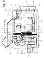
- a compressor system 10 has two screw compressors as compressor stages 11, 12 on.
- the compressor stages are surrounded by a housing 13, which is heat and is designed to be soundproof, various openings for the entry of fresh air or Has cooling air, for the exit of a compressed air line and warm air and in addition various auxiliary units are arranged.
- the compressor stages 11, 12 are driven by an electric main drive motor 14. This is coupled to the compressor stages via a belt drive 15.
- the fresh air enters the housing 13 via an intake silencer 16 and becomes partly supplied to a suction filter 17 and partly via the compressor stages 11, 12 passed as cooling air.
- the associated air flows are shown in FIG. 1 and 2 outlined in bold. A total of three air flows can be seen, namely the fresh air 18, which is compressed to compressed air in the compressor stages 11, 12, the cooling air 19, the outside bypasses the compressor stages 11, 12, and the cooling air 20, which the Main drive motor 14 passes and in parallel via an intercooler (first cooler) 21 and an aftercooler (last cooler) 22 is passed.
- the two cooling air streams 19, 20 are combined to form an exhaust air stream 23.
- the fresh air flow 18 and the cooling air flow 19 occur as a common one Airflow through the intake silencer 16 into the housing 13 and divide only there according to the existing pressure and temperature conditions.
- the compressed air generated in the compressor stages exits via a pipeline 24 Housing 13 out.
- the components of the compressor system 10 mentioned are special in the housing 13 Arranged in a way to achieve the best possible thermal conditions:
- the housing 13 is divided by an upright partition 25 into a compressor room 26 and a cooler space 27.
- the housing 13 itself is essentially rectangular designed with bottom wall 28, large side walls 29, 30, smaller end walls 31, 32 and top wall 33.
- the partition wall 25 runs parallel to the end walls 31, 32 and creates in the housing 13 about a division of 1/3 to 2/3, the cooler room 27 is almost twice as large as the compressor room 26.
- the partition 25 does not extend from the bottom wall 28 over the entire height of the housing 13. Rather, an upper part of the housing 13 forms an exhaust air chamber 34 which bounded downwards relative to the cooler space 27 by the side by side (parallel) cooler 21, 22, optionally additionally by an oil cooler 35. Between the compressor chamber 26 and the exhaust air chamber 34 is also a Transition provided, namely a narrow exhaust air inlet 36, also referred to as an ejector. The heated cooling air flow 19 enters the exhaust air chamber 34 via the exhaust air inlet 36 on.
- the compressor chamber 26 In the compressor chamber 26 are the two compressor stages 11, 12, the intake silencer 16, the suction filter 17, a suction regulator 37 and unspecified pipes arranged.
- the main drive motor 14 is provided in the cooler chamber 27 Belt drive 15, two fans 38, 39 with their electric drive motors 40, 41 for the two coolers 21, 22 and the latter, optionally also the oil cooler 35.
- Die Compressed air-carrying pipeline 24 preferably runs through the cooler chamber 27.
- a drive shaft 42 of the first compressor stage 11 extends through the partition 25, so that a drive pulley 43 is already arranged in the cooler space 27.
- the partition 25 is designed to be heat-insulating. Temperature changes on a Side of the partition 25 thus does not affect the temperature level, or only very slowly on the other side of the partition.
- Fig. 3 gives an overview of the order of different units during manufacture the compressed air as well as the control engineering dependencies of individual units.
- the flow of compressed air is shown in bold, oil lines, electrical lines - also signal lines - in contrast, only with a simple line width. Not fat either mechanical connections are drawn, for example from the main drive motor 14 to the two compressor stages 11, 12.
- the compressed air generated is stored in a compressed air container 44 outside the housing 13 and fed from there into a compressed air network, not shown.
- a pressure sensor 45 reports the pressure prevailing in the compressed air tank 44 to a control unit 46.
- This has the function of a compressor control for providing a sufficient amount of compressed air.
- Such pressure-dependent controls for switching the drive of compressor stages 11, 12 on and off are known in principle.
- the control unit 46 has to perform additional tasks depending on certain measured variables.
- a compressed air dryer 47 is provided in front of the compressed air container 44 (as shown here) or after it. The moisture and condensate present in the compressed air are removed here.
- the efficiency of the compressed air dryer is strongly dependent on the inlet temperature of the ambient temperature, the volume flow and the operating pressure.
- a temperature sensor 48 is arranged upstream of the compressed air dryer 47 to record the inlet temperature. The actual value recorded here is also fed to the control unit 46.
- sensors 49, 50, 51 are arranged upstream of the suction filter 17 and can be on the outside, for example Housing 13 may be provided. These sensors also deliver their measured values to the control unit 46th
- the drive motors 40, 41 for the Fans 38, 39 of the two coolers 21, 22 are controlled by the control unit 46.
- the control unit only reacts depending on the pressure values on Sensor 45. After falling below a minimum, the drive motor 14 starts and runs with 100% performance. The drive motors 40, 41 for the fans run synchronously with this the cooler 21, 22. After reaching a maximum pressure, the control unit switches 46 the main drive motor 14 back to about 30% of the power, so that the two Compressor stages 11, 12 work in idle mode and compressed air is no longer generated (Idle-control). The drive motors 40, 41 continue to run with unchanged power. Intercooler 21 and aftercooler 22 cool suddenly.
- the speed is adjusted as a function of the measured value at the pressure sensor 45 of the compressor stages to the current compressed air requirement. Less than 50% of the At full capacity, the compressor stages generally work uneconomically. It takes place then a transition to idle mode is better. They also work with this regulation Motors 40, 41 for the fans of the coolers 21, 22 but always at full power, provided that Compressor stages 11, 12 are driven at all. At part load speed and at idle therefore cool the coolers 21, 22 strongly.
- the compressor stages 11, 12 are analogous to 1. and 2. between full load and idle or driven between full load, partial load and idling. Analogue to the load, too electrical power of the motors 40, 41 for the fans of the coolers 21, 22 varies so that the temperatures of the coolers 21, 22 largely even when idling or in partial load operation remain stable and larger temperature gradients are avoided.
- the one from the last cooler of a compressor system in this case from the aftercooler 22 escaping compressed air is saturated with water vapor and is usually in the downstream dryer 47 dried.
- the latter is for a certain inlet temperature range of the compressed air and adheres to this temperature range its best efficiency or lowest energy consumption.
- the engine 41 for the cooler 22 is controlled by the control unit 46 as a function of the compressed air temperature controlled so that the dryer 47 work in its optimal range can.
- the temperature at the sensor 48 is recorded before entering the dryer 47 and processed by the control unit 46 to control the motor 41.
- the overall efficiency of compressed air generation improves with the cooling of the Compressed air between the compressor stages. Reduced cooling to maintain the "safety distance" from the dew point reduces the overall efficiency. It is advantageous to adapt the cooling to the current dew point.
- the climatic conditions at the place of use are recorded and recorded permanently the regulation of cooling is taken into account.
- the sensors 49, 50, 51 for example on the outside of the housing 13, current pressure, temperature and humidity values to the control unit 46. This can be based on empirical values and corresponding Characteristic curves are the values for the compressed air before entering the intercooler 21 determine. In the same, the compressed air is as close as possible to the dew point cooled down without falling below it. A takes place in the control unit 46 Calculate the dew point and determine and provide the electrical Power of the motor 40 for the fan of the intercooler 21.
- cooling air ducts can also be provided be changeable depending on the parameters mentioned, Cooling air flaps, not shown, for diverting the coolers 21, 22 that otherwise act on them Cooling air.
- the fans can be operated without changing their performance continue. Instead, all or part of the cooling air is directed around the cooler or led out of the housing 13 elsewhere.
- the intended ones Control flaps are driven in a suitable manner, in particular electrically.
- the fans 38, 39 are arranged so that only the respectively assigned cooler 21, 22 is acted upon becomes. Between the coolers 21, 22 there is also a thermally insulated (right) Partition 52 arranged.
- the oil cooler 35 can - as in Fig. 1 - arranged in the plane of the intercooler 21 and be acted upon by its fan 38.
- the oil cooler is preferably different Arranged, for example after the cooling air flow 20 has entered the cooler space 27, especially in connection with an intake silencer 53.
- a separate Fan 58 may be provided.
- a temperature sensor 54 is arranged downstream of the intercooler 21 or the second one or last compressor stage 12 upstream.
- the measured temperature value is - just like the values measured by the other sensors 48-51 - by the control unit 46 for controlling the drive motors 40, 41 and, if necessary, the motor for the Oil cooler 35 and 57 evaluated.
- FIG. 4 illustrates the temperatures and volume flows occurring at full load operation (FIG. 4) on the one hand and idle operation (FIG. 5) on the other hand.
- the associated Numerical values can be found in the table provided at the end of the description.
- the temperatures of the compressed air at various locations in the compressor system are recorded, namely the temperature T1 of the compressed air following the first compressor 11 and before entering the intercooler 21, the temperature T2 after the compressed air has escaped from the intercooler 21, the temperature T3 following the second compressor 12 and before entering the aftercooler 22, the temperature T4 after the compressed air has escaped from the aftercooler 22 and the temperature T5 between the second compressor 12 and a vent valve 55.
- the latter is to release the excess compressed air a vent silencer 56 connected.
- the compressed air in the intercooler 21 should only be one Temperature above the pressure dew point are cooled.
- the temperatures T2 in 4 and 5 (45 ° C and 40 ° C) are each above that to be considered at this point Dew point.
- the temperature T3 is that in the aftercooler 22 incoming compressed air at full load about 250 ° C. After going into idle switch off the fans 38, 39 or are reduced to low speeds. Hot compressed air no longer flows through the aftercooler 22. The cools accordingly Aftercooler 22 starts relatively slowly, starting from 250 ° C. The temperature T4 (30 ° C) is only reached after a long idle time. In practice, the compressors 11 run beforehand, 12 again.
- a volume flow V2 following the ventilation silencer 56 changes accordingly between 0% (full load) and 10 - 15% (idle).
Landscapes
- Engineering & Computer Science (AREA)
- Mechanical Engineering (AREA)
- General Engineering & Computer Science (AREA)
- Compressor (AREA)
- Applications Or Details Of Rotary Compressors (AREA)
- Control Of Multiple Motors (AREA)
- Compressors, Vaccum Pumps And Other Relevant Systems (AREA)
- Control Of Positive-Displacement Pumps (AREA)
Abstract
Description
- Fig. 1
- eine Kompressoranlage mit zwei Verdichterstufen, jeweils als ölfreie, luftgekühlte Schraubenkompressoren ausgeführt,
- Fig. 2
- eine Seitenansicht der Kompressoranlage gem. Fig.1,
- Fig. 3
- ein Diagramm mit auseinandergezogener Darstellung der Komponenten einer Kompressoranlage mit zwei Verdichterstufen,
- Fig. 4
- ein Diagramm zur Darstellung der Volumenströme und Temperaturen im Volllastbetrieb,
- Fig. 5
- ein Diagramm zur Darstellung der Volumenströme und Temperaturen im Leerlaufbetrieb.
Außerhalb des Gehäuses 13 ist z.B. vor dem Druckluftbehälter 44 (wie hier gezeigt) oder nach demselben ein Drucklufttrockner 47 vorgesehen. Hier werden die in der Druckluft vorhandene Feuchte und das Kondensat ausgeschieden. Der Wirkungsgrad des Drucklufttrockners ist stark abhängig von der Eintrittstemperatur der Umgebungstemperatur, dem Volumenstrom und dem Betriebsüberdruck. Zur Erfassung der Eintrittstemperatur ist dem Drucklufttrockner 47 ein Temperatursensor 48 vorgeordnet. Der hier erfasste IstWert wird ebenfalls der Regelungseinheit 46 zugeführt.
genannten Regelungen können auch miteinander kombiniert werden.
| Temperaturen T und Volumenströme V | |||
| T | V | Ort | Betriebszustand |
| V1 = 100% | vor dem Ansaugfilter 17 | Volllast | |
| V2 =0% | Entlüftungsschalldämpfer 56 | Volllast | |
| T1 = 200°C | zwischen erstem Verdichter 11 und Zwischenkühler 21 | Volllast | |
| T2 = 45°C | nach Austritt aus dem Zwischenkühler 21 | Volllast | |
| T3 = 250°C | V3 = 100% | zwischen zweitem Verdichter 12 und Nachkühler 22 | Volllast |
| T4 = 30°C | nach Austritt aus dem Nachkühler 22 | Volllast | |
| T6 = 60°C | vor Eintritt in den Ölkühler 35/57 | Volllast | |
| T7 = 40°C | nach Austritt aus dem Ölkühler 35/57 | Volllast | |
| V1 = 10-15% | vor dem Ansaugfilter 17 | Leerlauf | |
| V2 = 10-15% | Entlüftungsschalldämpfer 56 | Leerlauf | |
| T1 = 150°C | zwischen erstem Verdichter 11 und Zwischenkühler 21 | Leerlauf | |
| T2 = 40°C | nach Austritt aus dem Zwischenkühler 21 | Leerlauf | |
| T3 = 30°-250°C | V3 = 0% | zwischen zweitem Verdichter 12 und Nachkühler 22 | Leerlauf |
| T4 = 30°C | nach Austritt aus dem Nachkühler 22 | Leerlauf | |
| T5 = 150°C | zwischen zweitem Verdichter 12 und Entlüftungsventil 55 | Leerlauf | |
| T6 = 40°C | vor Eintritt in den Ölkühler 35/57 | Leerlauf | |
| T7 = 35°C | nach Austritt aus dem Ölkühler 35/57 | Leerlauf |
- 10
- Kompressoranlage
- 11
- erste Verdichterstufe
- 12
- zweite Verdichterstufe
- 13
- Gehäuse
- 14
- elektrischer Hauptantriebsmotor
- 15
- Riementrieb
- 16
- Ansaugschalldämpfer
- 17
- Ansaugfilter
- 18
- Frischluftstrom
- 19
- Kühlluftstrom
- 20
- Kühlluftstrom
- 21
- Zwischenkühler
- 22
- Nachkühler
- 23
- Abluftstrom
- 24
- Rohrleitung
- 25
- Trennwand
- 26
- Kompressorraum
- 27
- Kühlerraum
- 28
- Bodenwand
- 29
- Seitenwand
- 30
- Seitenwand
- 31
- Stirnwand
- 32
- Stirnwand
- 33
- Oberwand
- 34
- Abluftkammer
- 35
- Ölkühler
- 36
- Ablufteinlass
- 37
- Ansaugregler
- 38
- Lüfter
- 39
- Lüfter
- 40
- elektrischer Antriebsmotor
- 41
- elektrischer Antriebsmotor
- 42
- Antriebswelle
- 43
- Riemenscheibe
- 44
- Druckluftbehälter
- 45
- Drucksensor
- 46
- Regelungseinheit
- 47
- Druckluft- Trockner
- 48
- Temperatur-Sensor
- 49
- Temperatur-Sensor
- 50
- Feuchte-Sensor
- 51
- Druck-Sensor
- 52
- Trennwand
- 53
- Ansaugschalldämpfer
- 54
- Temperatur-Sensor
- 55
- Entlüftungsventil
- 56
- Entlüftungsschalldämpfer
- 57
- Ölkühler
- 58
- Lüfter mit Motor
Claims (11)
- Kompressoranlage (10) mit mindestens zwei Verdichterstufen (11, 12) - einer ersten Verdichterstufe (11) und einer letzten Verdichterstufe (12) - und mit einem Zwischenkühler (21) für Druckluft im Anschluss an die erste Verdichterstufe (11) und wahlweise mit einem Nachkühler (22) für die Druckluft im Anschluss an die letzte Verdichterstufe (12), wobei Zwischenkühler (21) und Nachkühler (22) durch Lüfter (38, 39) mit Kühlluft beaufschlagt werden, gekennzeichnet durch Mittel zum Regeln der Kühlluftmenge für den Zwischenkühler (21).
- Kompressoranlage nach Anspruch 1, dadurch gekennzeichnet, dass ein elektrischer Antriebsmotor (40) für den Lüfter (38) des Zwischenkühlers (21) regelbar ist.
- Kompressoranlage nach Anspruch 1 oder 2, gekennzeichnet durch Steuerorgane zum Umleiten zumindest eines Teils der für den Zwischenkühler (21) vorgesehenen Kühlluft.
- Kompressoranlage nach Anspruch 1 oder einem der weiteren Ansprüche, dadurch gekennzeichnet, dass Zwischenkühler (21) und Nachkühler (22) über jeweils separate Lüfter (38, 39) mit Kühlluft beaufschlagt werden.
- Kompressoranlage nach Anspruch 1 oder einem der weiteren Ansprüche, dadurch gekennzeichnet, dass Zwischenkühler (21) und Nachkühler (22) durch eine Trennwand (52) voneinander getrennt angeordnet sind.
- Kompressoranlage nach Anspruch 1 oder einem der weiteren Ansprüche, gekennzeichnet durch Mittel zum Regeln der Kühlluftmenge für den Nachkühler (22).
- Kompressoranlage nach Anspruch 6, dadurch gekennzeichnet, dass ein elektrischer Antriebsmotor (41) für den Lüfter (39) des Nachkühlers (22) regelbar ist.
- Kompressoranlage nach Anspruch 6 oder 7, gekennzeichnet durch Steuerorgane zum Umleiten zumindest eines Teils der für den Nachkühler (22) vorgesehenen Kühlluft.
- Kompressor mit mindestens einer Verdichterstufe (12) und einem Nachkühler (22) für die Druckluft, wobei der Nachkühler durch einen Lüfter mit Kühlluft beaufschlagt wird, gekennzeichnet durch Mittel zum Regeln der Kühlluftmenge für den Nachkühler (22).
- Verfahren zum Betreiben einer Kompressoranlage (10) mit mindestens zwei Verdichterstufen - einer ersten Verdichterstufe (11) und einer letzten Verdichterstufe (12) - und mit einem Zwischenkühler (21) für Druckluft im Anschluss an die erste Verdichterstufe (11) und insbesondere einem Nachkühler (22) für die Druckluft im Anschluss an die letzte Verdichterstufe (12), wobei Zwischenkühler (21) und Nachkühler (22) durch Lüfter mit Kühlluft beaufschlagt werden, dadurch gekennzeichnet, dass die dem Zwischenkühler (21) zugeführte Kühlluftmenge in Abhängigkeit von der Leistung der ersten Verdichterstufe (21) und/oder von äußeren klimatischen Bedingungen geregelt wird.
- Verfahren zum Betreiben einer Kompressoranlage (10) mit mindestens einer Verdichterstufe (12) und einem Nachkühler (22) für die Druckluft, wobei der Nachkühler (22) durch einen Lüfter (39) mit Kühlluft beaufschlagt wird, dadurch gekennzeichnet, dass die dem Nachkühler (22) zugeführte Kühlluftmenge in Abhängigkeit von der Leistung der Verdichterstufe (12) und/oder von der Temperatur der Druckluft vor oder nach dem Nachkühler (23) geregelt wird.
Applications Claiming Priority (2)
| Application Number | Priority Date | Filing Date | Title |
|---|---|---|---|
| DE10117790 | 2001-04-10 | ||
| DE10117790A DE10117790A1 (de) | 2001-04-10 | 2001-04-10 | Kompressoranlage und Verfahren zum Betreiben einer Kompressoranlage |
Publications (3)
| Publication Number | Publication Date |
|---|---|
| EP1249603A2 true EP1249603A2 (de) | 2002-10-16 |
| EP1249603A3 EP1249603A3 (de) | 2004-09-01 |
| EP1249603B1 EP1249603B1 (de) | 2006-11-29 |
Family
ID=7681027
Family Applications (1)
| Application Number | Title | Priority Date | Filing Date |
|---|---|---|---|
| EP02006738A Expired - Lifetime EP1249603B1 (de) | 2001-04-10 | 2002-03-23 | Kompressoranlage und Verfahren zum Betreiben einer Kompressoranlage |
Country Status (3)
| Country | Link |
|---|---|
| EP (1) | EP1249603B1 (de) |
| AT (1) | ATE347032T1 (de) |
| DE (2) | DE10117790A1 (de) |
Cited By (5)
| Publication number | Priority date | Publication date | Assignee | Title |
|---|---|---|---|---|
| BE1018846A3 (fr) * | 2008-11-28 | 2011-10-04 | Hitachi Ind Equipment Sys | Compresseur a vis. |
| US20130098476A1 (en) * | 2011-10-21 | 2013-04-25 | Henderson Engineering Company, Inc. | Compressed gas drying system |
| US10174972B2 (en) | 2014-11-14 | 2019-01-08 | Kaeser Kompressoren Se | Intercooler bypass |
| EP3277958B1 (de) | 2015-03-30 | 2020-02-26 | Gardner Denver Deutschland GmbH | Kompressoranlage zur erzeugung von druckluft sowie verfahren zum betrieb einer druckluft erzeugenden kompressoranlage |
| CN116917626A (zh) * | 2021-03-02 | 2023-10-20 | 阿特拉斯·科普柯空气动力股份有限公司 | 移动式无油多级压缩机装置和控制此压缩机装置的方法 |
Families Citing this family (5)
| Publication number | Priority date | Publication date | Assignee | Title |
|---|---|---|---|---|
| DE102014019805B3 (de) * | 2014-11-14 | 2020-09-03 | Kaeser Kompressoren Se | Kompressoranlage zur Komprimierung von Gasen |
| JP7072463B2 (ja) * | 2018-07-31 | 2022-05-20 | コベルコ・コンプレッサ株式会社 | 圧縮機およびその運転方法 |
| DE202022002369U1 (de) * | 2022-11-04 | 2024-02-06 | Dirk Gros | Vorrichtung zur unterstützenden Bereitstellung von Ansauggas für fluideingespritzte Kompressoren mit optimierender Einflussnahme auf die Verdichtungsendtemperatur |
| DE102023135011A1 (de) * | 2023-12-13 | 2025-06-18 | Kaeser Kompressoren Se | Kompressoreinrichtung mit Kühlung und Verfahren zum Betreiben einer Kompressoreinrichtung |
| DE102023135013A1 (de) * | 2023-12-13 | 2025-06-18 | Kaeser Kompressoren Se | Kompressoreinrichtung mit Kühlung und Verfahren zum Betreiben einer Kompressoreinrichtung |
Family Cites Families (9)
| Publication number | Priority date | Publication date | Assignee | Title |
|---|---|---|---|---|
| DE6933394U (de) * | 1969-08-25 | 1970-02-19 | Loba Ing Dieter | Kolben- und kreiselkompressor mit luftkuehlung |
| DE3541838A1 (de) * | 1985-11-27 | 1987-06-04 | Kopp Gmbh Int Pipeline Service | Kompressor-anlage |
| DE4332917C2 (de) * | 1993-09-28 | 1998-10-29 | Joerg Fuhrmann | Verfahren zum Betreiben einer Kühleinrichtung mit Schockfroster und Anordnung zur Durchführung des Verfahrens |
| US5590539A (en) * | 1993-11-26 | 1997-01-07 | Omega Enterprises Inc. | Refrigeration apparatus and methods |
| BE1008367A3 (nl) * | 1994-01-25 | 1996-04-02 | Atlas Copco Airpower Nv | Kompressoreenheid. |
| JPH10184571A (ja) * | 1996-12-20 | 1998-07-14 | Ishikawajima Harima Heavy Ind Co Ltd | インバータ制御2段スクリュー圧縮機 |
| JPH1137053A (ja) * | 1997-07-23 | 1999-02-09 | Ishikawajima Harima Heavy Ind Co Ltd | インバータ駆動多段圧縮機の制御方法 |
| US6203285B1 (en) * | 1998-05-18 | 2001-03-20 | Westinghouse Air Brake Company | Compressor intercooler unloader arrangement |
| DE19933989A1 (de) * | 1999-07-20 | 2001-01-25 | Linde Gas Ag | Verfahren und Kompressormodul zum Verdichten eines Gasstromes |
-
2001
- 2001-04-10 DE DE10117790A patent/DE10117790A1/de not_active Withdrawn
-
2002
- 2002-03-23 EP EP02006738A patent/EP1249603B1/de not_active Expired - Lifetime
- 2002-03-23 AT AT02006738T patent/ATE347032T1/de not_active IP Right Cessation
- 2002-03-23 DE DE50208821T patent/DE50208821D1/de not_active Expired - Lifetime
Cited By (7)
| Publication number | Priority date | Publication date | Assignee | Title |
|---|---|---|---|---|
| BE1018846A3 (fr) * | 2008-11-28 | 2011-10-04 | Hitachi Ind Equipment Sys | Compresseur a vis. |
| US20130098476A1 (en) * | 2011-10-21 | 2013-04-25 | Henderson Engineering Company, Inc. | Compressed gas drying system |
| US8951339B2 (en) * | 2011-10-21 | 2015-02-10 | Henderson Engineering Company, Inc. | Compressed gas drying system |
| US10174972B2 (en) | 2014-11-14 | 2019-01-08 | Kaeser Kompressoren Se | Intercooler bypass |
| EP3277958B1 (de) | 2015-03-30 | 2020-02-26 | Gardner Denver Deutschland GmbH | Kompressoranlage zur erzeugung von druckluft sowie verfahren zum betrieb einer druckluft erzeugenden kompressoranlage |
| EP3277958B2 (de) † | 2015-03-30 | 2023-12-27 | Gardner Denver Deutschland GmbH | Kompressoranlage zur erzeugung von druckluft sowie verfahren zum betrieb einer druckluft erzeugenden kompressoranlage |
| CN116917626A (zh) * | 2021-03-02 | 2023-10-20 | 阿特拉斯·科普柯空气动力股份有限公司 | 移动式无油多级压缩机装置和控制此压缩机装置的方法 |
Also Published As
| Publication number | Publication date |
|---|---|
| ATE347032T1 (de) | 2006-12-15 |
| EP1249603A3 (de) | 2004-09-01 |
| EP1249603B1 (de) | 2006-11-29 |
| DE10117790A1 (de) | 2002-10-17 |
| DE50208821D1 (de) | 2007-01-11 |
Similar Documents
| Publication | Publication Date | Title |
|---|---|---|
| CH695869A5 (de) | Mehrstufiger, zwischen Last- und Leerlaufbetrieb umschaltbarer Verdichter. | |
| DE60132518T2 (de) | Schraubenkompressor für ein Kältegerät | |
| DE69511892T2 (de) | Gasturbinenkompressor der zapfluft liefert für industrielle zwecke | |
| DE10013098C2 (de) | Anlage zur Erzeugung von Druckluft | |
| JP3059116B2 (ja) | 多段式ガス圧縮機、サーモスタット制御のインタークーラーシステム、並びに多段式ガス圧縮機内の水の凝縮を実質的に最少にするための方法 | |
| EP1249603A2 (de) | Kompressoranlage und Verfahren zum Betreiben einer Kompressoranlage | |
| EP3388621B1 (de) | Kompressoranlage mit interner luft-wasser-kühlung | |
| EP1886075B1 (de) | Kaelteanlage | |
| DE60123321T2 (de) | Verdichteranlage mit einem gesteuerten Kühlventilator | |
| DE10047940A1 (de) | Schraubenkompressionsvorrichtung und Verfahren zu deren Betriebssteuerung | |
| WO2003076781A1 (de) | Krafterzeugungsanlage | |
| DE10115648A1 (de) | Zweistufige Schraubenkompressoranlage und Verfahren zu ihrer Steuerung | |
| EP3146215B1 (de) | Mehrstufige verdichteranlage mit hydrodynamischer strömungskupplung | |
| CN210623084U (zh) | 喷油多级压缩机系统 | |
| DE10254016A1 (de) | Vorrichtung zur Kühlung von Ladeluft und Verfahren zum Betreiben einer derartigen Vorrichtung | |
| WO2009156146A1 (de) | Raumlufttechnisches gerät und verfahren zur verwendung eines solchen raumlufttechnischen gerätes | |
| WO1998025686A1 (de) | Druckwechselanlage zur gewinnung von sauerstoff aus der luft und verfahren zum betrieb einer solchen | |
| DE102017107601B4 (de) | Verfahren zur Steuerung eines Schraubenverdichters | |
| CN110939569B (zh) | 喷油多级压缩机装置和用于控制压缩机装置的方法 | |
| EP0592059A1 (de) | Verfahren und Vorrichtung zum Verdichten eines gasförmigen Mediums | |
| DE2303964A1 (de) | Kaelteanlage | |
| DE202022101072U1 (de) | Druckluftsystem | |
| DE4106046C2 (de) | ||
| DE102004063840B3 (de) | Verfahren zur Klimatisierung eines Raumes und Kaltluft-Kältemaschinen-Anlagen zur Durchführung des Verfahrens | |
| DE1576222C3 (de) | Mehrzyhndrige Zweitaktdiesel brennkraftmaschine mit Abgasturboauf ladung |
Legal Events
| Date | Code | Title | Description |
|---|---|---|---|
| PUAI | Public reference made under article 153(3) epc to a published international application that has entered the european phase |
Free format text: ORIGINAL CODE: 0009012 |
|
| AK | Designated contracting states |
Kind code of ref document: A2 Designated state(s): AT BE CH CY DE DK ES FI FR GB GR IE IT LI LU MC NL PT SE TR |
|
| AX | Request for extension of the european patent |
Free format text: AL;LT;LV;MK;RO;SI |
|
| PUAL | Search report despatched |
Free format text: ORIGINAL CODE: 0009013 |
|
| AK | Designated contracting states |
Kind code of ref document: A3 Designated state(s): AT BE CH CY DE DK ES FI FR GB GR IE IT LI LU MC NL PT SE TR |
|
| AX | Request for extension of the european patent |
Extension state: AL LT LV MK RO SI |
|
| 17P | Request for examination filed |
Effective date: 20040928 |
|
| AKX | Designation fees paid |
Designated state(s): AT BE CH CY DE DK ES FI FR GB GR IE IT LI LU MC NL PT SE TR |
|
| GRAP | Despatch of communication of intention to grant a patent |
Free format text: ORIGINAL CODE: EPIDOSNIGR1 |
|
| GRAS | Grant fee paid |
Free format text: ORIGINAL CODE: EPIDOSNIGR3 |
|
| RIC1 | Information provided on ipc code assigned before grant |
Ipc: F04C 23/00 20060101ALI20060801BHEP Ipc: F04B 41/00 20060101ALI20060801BHEP Ipc: F04C 29/04 20060101ALI20060801BHEP Ipc: F04B 25/00 20060101AFI20060801BHEP Ipc: F04C 28/00 20060101ALI20060801BHEP |
|
| GRAA | (expected) grant |
Free format text: ORIGINAL CODE: 0009210 |
|
| AK | Designated contracting states |
Kind code of ref document: B1 Designated state(s): AT BE CH CY DE DK ES FI FR GB GR IE IT LI LU MC NL PT SE TR |
|
| PG25 | Lapsed in a contracting state [announced via postgrant information from national office to epo] |
Ref country code: NL Free format text: LAPSE BECAUSE OF FAILURE TO SUBMIT A TRANSLATION OF THE DESCRIPTION OR TO PAY THE FEE WITHIN THE PRESCRIBED TIME-LIMIT Effective date: 20061129 Ref country code: IE Free format text: LAPSE BECAUSE OF FAILURE TO SUBMIT A TRANSLATION OF THE DESCRIPTION OR TO PAY THE FEE WITHIN THE PRESCRIBED TIME-LIMIT Effective date: 20061129 Ref country code: FI Free format text: LAPSE BECAUSE OF FAILURE TO SUBMIT A TRANSLATION OF THE DESCRIPTION OR TO PAY THE FEE WITHIN THE PRESCRIBED TIME-LIMIT Effective date: 20061129 |
|
| REG | Reference to a national code |
Ref country code: GB Ref legal event code: FG4D Free format text: NOT ENGLISH |
|
| REG | Reference to a national code |
Ref country code: CH Ref legal event code: EP |
|
| REG | Reference to a national code |
Ref country code: IE Ref legal event code: FG4D Free format text: LANGUAGE OF EP DOCUMENT: GERMAN |
|
| REF | Corresponds to: |
Ref document number: 50208821 Country of ref document: DE Date of ref document: 20070111 Kind code of ref document: P |
|
| GBT | Gb: translation of ep patent filed (gb section 77(6)(a)/1977) |
Effective date: 20070201 |
|
| PG25 | Lapsed in a contracting state [announced via postgrant information from national office to epo] |
Ref country code: SE Free format text: LAPSE BECAUSE OF FAILURE TO SUBMIT A TRANSLATION OF THE DESCRIPTION OR TO PAY THE FEE WITHIN THE PRESCRIBED TIME-LIMIT Effective date: 20070228 Ref country code: DK Free format text: LAPSE BECAUSE OF FAILURE TO SUBMIT A TRANSLATION OF THE DESCRIPTION OR TO PAY THE FEE WITHIN THE PRESCRIBED TIME-LIMIT Effective date: 20070228 |
|
| PG25 | Lapsed in a contracting state [announced via postgrant information from national office to epo] |
Ref country code: ES Free format text: LAPSE BECAUSE OF FAILURE TO SUBMIT A TRANSLATION OF THE DESCRIPTION OR TO PAY THE FEE WITHIN THE PRESCRIBED TIME-LIMIT Effective date: 20070312 |
|
| PG25 | Lapsed in a contracting state [announced via postgrant information from national office to epo] |
Ref country code: PT Free format text: LAPSE BECAUSE OF FAILURE TO SUBMIT A TRANSLATION OF THE DESCRIPTION OR TO PAY THE FEE WITHIN THE PRESCRIBED TIME-LIMIT Effective date: 20070430 |
|
| NLV1 | Nl: lapsed or annulled due to failure to fulfill the requirements of art. 29p and 29m of the patents act | ||
| ET | Fr: translation filed | ||
| REG | Reference to a national code |
Ref country code: IE Ref legal event code: FD4D |
|
| PLBI | Opposition filed |
Free format text: ORIGINAL CODE: 0009260 |
|
| PLAX | Notice of opposition and request to file observation + time limit sent |
Free format text: ORIGINAL CODE: EPIDOSNOBS2 |
|
| 26 | Opposition filed |
Opponent name: KNORR-BREMSE AG Effective date: 20070829 |
|
| REG | Reference to a national code |
Ref country code: CH Ref legal event code: PL |
|
| PG25 | Lapsed in a contracting state [announced via postgrant information from national office to epo] |
Ref country code: MC Free format text: LAPSE BECAUSE OF NON-PAYMENT OF DUE FEES Effective date: 20070331 |
|
| PLBB | Reply of patent proprietor to notice(s) of opposition received |
Free format text: ORIGINAL CODE: EPIDOSNOBS3 |
|
| PG25 | Lapsed in a contracting state [announced via postgrant information from national office to epo] |
Ref country code: LI Free format text: LAPSE BECAUSE OF NON-PAYMENT OF DUE FEES Effective date: 20070331 Ref country code: CH Free format text: LAPSE BECAUSE OF NON-PAYMENT OF DUE FEES Effective date: 20070331 |
|
| PG25 | Lapsed in a contracting state [announced via postgrant information from national office to epo] |
Ref country code: GR Free format text: LAPSE BECAUSE OF FAILURE TO SUBMIT A TRANSLATION OF THE DESCRIPTION OR TO PAY THE FEE WITHIN THE PRESCRIBED TIME-LIMIT Effective date: 20070301 |
|
| PG25 | Lapsed in a contracting state [announced via postgrant information from national office to epo] |
Ref country code: AT Free format text: LAPSE BECAUSE OF NON-PAYMENT OF DUE FEES Effective date: 20070323 |
|
| PG25 | Lapsed in a contracting state [announced via postgrant information from national office to epo] |
Ref country code: LU Free format text: LAPSE BECAUSE OF NON-PAYMENT OF DUE FEES Effective date: 20070323 Ref country code: CY Free format text: LAPSE BECAUSE OF FAILURE TO SUBMIT A TRANSLATION OF THE DESCRIPTION OR TO PAY THE FEE WITHIN THE PRESCRIBED TIME-LIMIT Effective date: 20061129 |
|
| PG25 | Lapsed in a contracting state [announced via postgrant information from national office to epo] |
Ref country code: TR Free format text: LAPSE BECAUSE OF FAILURE TO SUBMIT A TRANSLATION OF THE DESCRIPTION OR TO PAY THE FEE WITHIN THE PRESCRIBED TIME-LIMIT Effective date: 20061129 |
|
| PLAB | Opposition data, opponent's data or that of the opponent's representative modified |
Free format text: ORIGINAL CODE: 0009299OPPO |
|
| R26 | Opposition filed (corrected) |
Opponent name: KNORR-BREMSE AG Effective date: 20070829 |
|
| PLBP | Opposition withdrawn |
Free format text: ORIGINAL CODE: 0009264 |
|
| PLBD | Termination of opposition procedure: decision despatched |
Free format text: ORIGINAL CODE: EPIDOSNOPC1 |
|
| PLBM | Termination of opposition procedure: date of legal effect published |
Free format text: ORIGINAL CODE: 0009276 |
|
| STAA | Information on the status of an ep patent application or granted ep patent |
Free format text: STATUS: OPPOSITION PROCEDURE CLOSED |
|
| 27C | Opposition proceedings terminated |
Effective date: 20101028 |
|
| PGFP | Annual fee paid to national office [announced via postgrant information from national office to epo] |
Ref country code: IT Payment date: 20120317 Year of fee payment: 11 |
|
| PGFP | Annual fee paid to national office [announced via postgrant information from national office to epo] |
Ref country code: FR Payment date: 20130325 Year of fee payment: 12 Ref country code: GB Payment date: 20130320 Year of fee payment: 12 |
|
| PG25 | Lapsed in a contracting state [announced via postgrant information from national office to epo] |
Ref country code: IT Free format text: LAPSE BECAUSE OF NON-PAYMENT OF DUE FEES Effective date: 20130323 |
|
| GBPC | Gb: european patent ceased through non-payment of renewal fee |
Effective date: 20140323 |
|
| REG | Reference to a national code |
Ref country code: FR Ref legal event code: ST Effective date: 20141128 |
|
| PG25 | Lapsed in a contracting state [announced via postgrant information from national office to epo] |
Ref country code: GB Free format text: LAPSE BECAUSE OF NON-PAYMENT OF DUE FEES Effective date: 20140323 Ref country code: FR Free format text: LAPSE BECAUSE OF NON-PAYMENT OF DUE FEES Effective date: 20140331 |
|
| PGFP | Annual fee paid to national office [announced via postgrant information from national office to epo] |
Ref country code: BE Payment date: 20150311 Year of fee payment: 14 |
|
| PG25 | Lapsed in a contracting state [announced via postgrant information from national office to epo] |
Ref country code: BE Free format text: LAPSE BECAUSE OF NON-PAYMENT OF DUE FEES Effective date: 20160331 |
|
| REG | Reference to a national code |
Ref country code: DE Ref legal event code: R084 Ref document number: 50208821 Country of ref document: DE |
|
| PGFP | Annual fee paid to national office [announced via postgrant information from national office to epo] |
Ref country code: DE Payment date: 20170331 Year of fee payment: 16 |
|
| REG | Reference to a national code |
Ref country code: DE Ref legal event code: R119 Ref document number: 50208821 Country of ref document: DE |
|
| PG25 | Lapsed in a contracting state [announced via postgrant information from national office to epo] |
Ref country code: DE Free format text: LAPSE BECAUSE OF NON-PAYMENT OF DUE FEES Effective date: 20181002 |