EP1249306B1 - Antrieb für Maschinenaggregate, wie Schlitten, Greifeinrichtungen und dergleichen - Google Patents
Antrieb für Maschinenaggregate, wie Schlitten, Greifeinrichtungen und dergleichen Download PDFInfo
- Publication number
- EP1249306B1 EP1249306B1 EP02007783A EP02007783A EP1249306B1 EP 1249306 B1 EP1249306 B1 EP 1249306B1 EP 02007783 A EP02007783 A EP 02007783A EP 02007783 A EP02007783 A EP 02007783A EP 1249306 B1 EP1249306 B1 EP 1249306B1
- Authority
- EP
- European Patent Office
- Prior art keywords
- spindle
- drive according
- motor
- drive
- threaded spindle
- Prior art date
- Legal status (The legal status is an assumption and is not a legal conclusion. Google has not performed a legal analysis and makes no representation as to the accuracy of the status listed.)
- Expired - Lifetime
Links
Images


Classifications
-
- B—PERFORMING OPERATIONS; TRANSPORTING
- B23—MACHINE TOOLS; METAL-WORKING NOT OTHERWISE PROVIDED FOR
- B23Q—DETAILS, COMPONENTS, OR ACCESSORIES FOR MACHINE TOOLS, e.g. ARRANGEMENTS FOR COPYING OR CONTROLLING; MACHINE TOOLS IN GENERAL CHARACTERISED BY THE CONSTRUCTION OF PARTICULAR DETAILS OR COMPONENTS; COMBINATIONS OR ASSOCIATIONS OF METAL-WORKING MACHINES, NOT DIRECTED TO A PARTICULAR RESULT
- B23Q5/00—Driving or feeding mechanisms; Control arrangements therefor
- B23Q5/54—Arrangements or details not restricted to group B23Q5/02 or group B23Q5/22 respectively, e.g. control handles
- B23Q5/56—Preventing backlash
-
- B—PERFORMING OPERATIONS; TRANSPORTING
- B23—MACHINE TOOLS; METAL-WORKING NOT OTHERWISE PROVIDED FOR
- B23Q—DETAILS, COMPONENTS, OR ACCESSORIES FOR MACHINE TOOLS, e.g. ARRANGEMENTS FOR COPYING OR CONTROLLING; MACHINE TOOLS IN GENERAL CHARACTERISED BY THE CONSTRUCTION OF PARTICULAR DETAILS OR COMPONENTS; COMBINATIONS OR ASSOCIATIONS OF METAL-WORKING MACHINES, NOT DIRECTED TO A PARTICULAR RESULT
- B23Q5/00—Driving or feeding mechanisms; Control arrangements therefor
- B23Q5/22—Feeding members carrying tools or work
- B23Q5/34—Feeding other members supporting tools or work, e.g. saddles, tool-slides, through mechanical transmission
- B23Q5/38—Feeding other members supporting tools or work, e.g. saddles, tool-slides, through mechanical transmission feeding continuously
- B23Q5/40—Feeding other members supporting tools or work, e.g. saddles, tool-slides, through mechanical transmission feeding continuously by feed shaft, e.g. lead screw
- B23Q5/402—Feeding other members supporting tools or work, e.g. saddles, tool-slides, through mechanical transmission feeding continuously by feed shaft, e.g. lead screw in which screw or nut can both be driven
-
- Y—GENERAL TAGGING OF NEW TECHNOLOGICAL DEVELOPMENTS; GENERAL TAGGING OF CROSS-SECTIONAL TECHNOLOGIES SPANNING OVER SEVERAL SECTIONS OF THE IPC; TECHNICAL SUBJECTS COVERED BY FORMER USPC CROSS-REFERENCE ART COLLECTIONS [XRACs] AND DIGESTS
- Y10—TECHNICAL SUBJECTS COVERED BY FORMER USPC
- Y10T—TECHNICAL SUBJECTS COVERED BY FORMER US CLASSIFICATION
- Y10T74/00—Machine element or mechanism
- Y10T74/18—Mechanical movements
- Y10T74/18568—Reciprocating or oscillating to or from alternating rotary
- Y10T74/18576—Reciprocating or oscillating to or from alternating rotary including screw and nut
- Y10T74/18648—Carriage surrounding, guided by, and primarily supported by member other than screw [e.g., linear guide, etc.]
-
- Y—GENERAL TAGGING OF NEW TECHNOLOGICAL DEVELOPMENTS; GENERAL TAGGING OF CROSS-SECTIONAL TECHNOLOGIES SPANNING OVER SEVERAL SECTIONS OF THE IPC; TECHNICAL SUBJECTS COVERED BY FORMER USPC CROSS-REFERENCE ART COLLECTIONS [XRACs] AND DIGESTS
- Y10—TECHNICAL SUBJECTS COVERED BY FORMER USPC
- Y10T—TECHNICAL SUBJECTS COVERED BY FORMER US CLASSIFICATION
- Y10T74/00—Machine element or mechanism
- Y10T74/18—Mechanical movements
- Y10T74/18568—Reciprocating or oscillating to or from alternating rotary
- Y10T74/18576—Reciprocating or oscillating to or from alternating rotary including screw and nut
- Y10T74/18656—Carriage surrounded, guided, and primarily supported by member other than screw [e.g., linear guide, etc.]
-
- Y—GENERAL TAGGING OF NEW TECHNOLOGICAL DEVELOPMENTS; GENERAL TAGGING OF CROSS-SECTIONAL TECHNOLOGIES SPANNING OVER SEVERAL SECTIONS OF THE IPC; TECHNICAL SUBJECTS COVERED BY FORMER USPC CROSS-REFERENCE ART COLLECTIONS [XRACs] AND DIGESTS
- Y10—TECHNICAL SUBJECTS COVERED BY FORMER USPC
- Y10T—TECHNICAL SUBJECTS COVERED BY FORMER US CLASSIFICATION
- Y10T74/00—Machine element or mechanism
- Y10T74/18—Mechanical movements
- Y10T74/18568—Reciprocating or oscillating to or from alternating rotary
- Y10T74/18576—Reciprocating or oscillating to or from alternating rotary including screw and nut
- Y10T74/18664—Shaft moves through rotary drive means
-
- Y—GENERAL TAGGING OF NEW TECHNOLOGICAL DEVELOPMENTS; GENERAL TAGGING OF CROSS-SECTIONAL TECHNOLOGIES SPANNING OVER SEVERAL SECTIONS OF THE IPC; TECHNICAL SUBJECTS COVERED BY FORMER USPC CROSS-REFERENCE ART COLLECTIONS [XRACs] AND DIGESTS
- Y10—TECHNICAL SUBJECTS COVERED BY FORMER USPC
- Y10T—TECHNICAL SUBJECTS COVERED BY FORMER US CLASSIFICATION
- Y10T74/00—Machine element or mechanism
- Y10T74/18—Mechanical movements
- Y10T74/18568—Reciprocating or oscillating to or from alternating rotary
- Y10T74/18576—Reciprocating or oscillating to or from alternating rotary including screw and nut
- Y10T74/18696—Reciprocating or oscillating to or from alternating rotary including screw and nut including means to selectively transmit power [e.g., clutch, etc.]
-
- Y—GENERAL TAGGING OF NEW TECHNOLOGICAL DEVELOPMENTS; GENERAL TAGGING OF CROSS-SECTIONAL TECHNOLOGIES SPANNING OVER SEVERAL SECTIONS OF THE IPC; TECHNICAL SUBJECTS COVERED BY FORMER USPC CROSS-REFERENCE ART COLLECTIONS [XRACs] AND DIGESTS
- Y10—TECHNICAL SUBJECTS COVERED BY FORMER USPC
- Y10T—TECHNICAL SUBJECTS COVERED BY FORMER US CLASSIFICATION
- Y10T74/00—Machine element or mechanism
- Y10T74/19—Gearing
- Y10T74/19642—Directly cooperating gears
- Y10T74/19698—Spiral
- Y10T74/19702—Screw and nut
Definitions
- the invention relates to a drive for machine units, such as Sledges, gripping devices and the like, according to the generic term of claim 1.
- a three-phase synchronous motor drives on the machine frame there is a rotatable ball screw on. She is engaged to a mother who is in a sled or Stand is rotatably mounted. Sledges and stands are on guides longitudinally displaceable relative to the machine frame. Dependent on on the stroke length or the required rapid traverse of the slide there are different limit speeds for the spindle and the nut in front. Above certain slenderness levels or off other design reasons of the ball screw can this also held in rotation and the nut driven in rotation become.
- Spindle drive devices are also known (DE 39 38 353 A1) with two spindle drive heads and one spindle with Right and left hand threads on the same threaded spindle section perform both translatory and rotary movements.
- the invention has for its object the generic drive to be trained so that for high positioning speeds Handling equipment and high-speed machining at Machine tools acceleration, rapid traverse and feed speeds are high.
- the drive torque is over the threaded spindle initiated.
- the threaded spindle with the two spindle areas of opposite pitch and the in Fixed mother becomes a at the same engine speed Increase in acceleration and travel speeds of the machine unit.
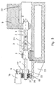
- Fig. 1 shows a drive which is designed as a feed drive, with which, for example, a carriage moves on machine tools become.
- Fig. 1 shows such a machine with a machine bed 1, on which a spindle 2 is rotatably mounted.
- the spindle for example A ball screw can be in a nut 7 out, which is axially and radially fixed to a bearing block 10 is attached to the machine bed 1.
- the spindle 2 has two spindle areas 3 and 4, the opposite pitch to have.
- the spindle area 3 can, for example, rise to the right and the spindle must be designed to rise to the left.
- the spindle 2 is driven by a motor 16, the motor shaft 17 of which is in alignment to the spindle 2 and with its end 5 via a coupling 18th is rotatably connected.
- the motor 16 is axially displaceable and will supported against rotation over the entire length of its travel.
- a guide 20 is used to guide the motor 16 a bracket 23 is attached to a side wall of the machine bed 1 is attached.
- the guide 20 has at least one guideway 21 provided on the console 23 and on the at least a guide shoe 22 is slidable. It is at the bottom an angle 19 is provided which supports the motor 16.
- the spindle 2 is over at least one bearing 14, preferably a roller bearing, with an axis 13 rotatably connected.
- the bearing 14 is by a nut 15, the is screwed onto the free spindle end 6, axially secured.
- the warehouse 14 is under the force of the mother 15 on a shoulder 26 of the Spindle 2.
- the axis 13 is in a bearing block 11 with at least one longitudinal bearing 12 out, which can be a sliding or a rolling bearing. Since the Spindle 2 in the manner described by means of the two bearing blocks 10, 11 is supported in the area of both ends, the limit speed the spindle 2 increases, which enables high travel speeds become.
- the carriage 9 is on its underside facing the machine bed 1 provided with a recess 27 in which the bearing block 11, the spindle end 6 and the bearing 14 are.
- the carriage 9 is on at least one guide shoe 28 Guide 29 slidably mounted at a distance above the guide 20 is provided for the motor 16. This will make the sled 9 not only guided over the nut 8 on the spindle 2, but also via the guide shoe 28 on the guide 29.
- the spindle 2 With the motor 16, the spindle 2 is rotated.
- the motor 16 and the other axially fixed to its motor shaft 17 Components move in the axial direction. Because of the slope direction of nut 8 and spindle area 4, the opposite to the direction of pitch of nut 7 and spindle area 3, the nut 8 moves with a rotating spindle 2 with an axial Relative movement to the spindle 2.
- the axial direction of movement of the Nut 8 is identical to the axial direction of movement Spindle 2, however, takes place at a higher speed.
- the carriage 9 in the Move the respective direction on the machine bed 1.
- the on the Carriage 9 transmitted movement is composed of it the axial movement of the spindle 2 and the axial relative movement between the nut 8 and the spindle 2. Through the additive superposition the movements result in high travel speeds and accelerations.
- Fig. 1 is the one end position of the carriage with solid lines 9 shown.
- the other end position is with dash-dotted lines of the carriage 9 indicated at maximum travel.
- Fig. 2 shows an embodiment in which the motor 16 is offset radially to the spindle 2 is provided on the carrier 19.
- the motor shaft 17 not directly with the spindle 2, but over a transmission, for example by a belt drive 30, connected.
- On the motor shaft 17 is a pulley 31, which has a Belt 32 is drivingly connected to a pulley 33 which sits on the spindle end 5 in a rotationally fixed manner.
- the carrier 19 is over the Guide shoe 22 supported on the guide track 21 on the bracket 23.
- the spindle end 5 is preferably by at least one bearing 34 a roller bearing, rotatably supported in the carrier 19.
- the warehouse 34 is axially secured by a nut 35 which is on the free end of the spindle end 5 is screwed.
- this embodiment is the same as the embodiment 1. Since the motor 16 is not axially behind the Spindle 2 is located, but provided in the area above the spindle is, this embodiment is shorter than the embodiment according to Fig. 1.
- Fig. 3 shows a drive system in which the spindle 2 only on one End is stored. There is no support and storage at the spindle end 6 provided so that the structural design of this embodiment is simpler than in the two previously described exemplary embodiments. Otherwise, the drive system according to FIG. 3 designed the same as the embodiment of FIG. 1. But it is also possible, this one-sided mounting of the spindle 2 in one embodiment to provide according to Fig. 2.
- the drive system 3 is advantageously suitable for relatively short travel distances. It can, as in the previous exemplary embodiments high speeds and accelerations can be achieved.
- Fig. 4 shows a drive system in which a second at the spindle end 6 Motor 16 is provided. This will make the spindle 2 of both Ends 5, 6 each driven by a motor 16, each is aligned with spindle 2.
- the two motor shafts 17 are each via a coupling 18 with the respective spindle end 5, 6 non-rotatably connected.
- the two motors 16 are each on the angular support 19 mounted, in contrast to the embodiment of FIG. 1 on the Guide track 29 is displaceable with the guide shoe 22.
- the Carriage 9 is with its guide shoe 27 on the same track 29 supported.
- the motors 16 are on the vertically below protruding legs of the angular support 19 attached and are close to the machine bed 1.
- the spindle 2 has according to the previous embodiments the spindle areas with the opposite pitch 3, 4, to which the nuts 7 and 8 are assigned.
- the two carriers 19 are mirror-symmetrical to each other, the Motors 16 against the spindle 2 by the projecting downwards Legs of the carrier 19 are covered. Because the spindle 2 on both Heavy-duty ends can also be rotated the carriage 9 with high speed and high acceleration be moved. 4 is again with solid lines one end position and with dash-dotted lines the other end position of the carriage 9 shown.
- Fig. 5 shows a drive system in which the motor 16 via a console 36 is mounted axially immovable on the console 23.
- the motor shaft 17 is in accordance with the embodiment of FIG the belt drive 30 with the spindle end 5 drive connected.
- the on the spindle end 5 located pulley 33 is different to the embodiment according to FIG. 2 axially fixed and is on one Sleeve 37 provided, which is designed as a splined shaft End 5 of the spindle 2 is seated against rotation.
- the sleeve 37 is at least a bearing 38, preferably a roller bearing, rotatable in the bracket 36 supported.
- the spindle end 5 moves in the axial direction relative to axially fixed pulley 33. Since the motor 16 with the Belt drive 30 in contrast to the previous embodiments is not moved axially, the moving masses are small. Thereby high speeds and accelerations can be achieved. For reasons of accuracy, the engagement is that of a splined shaft Spindle end 5 in the pulley 33 by the advantageous realized as a preloaded linear roller bearing 38.
- the spindle 2 is supported in the rest of the nuts 7, 8, which the spindle areas provided with opposite pitches 3 and 4 are assigned.
- the carriage 9 is over the guide shoe 28 supported on the linear guide 29.
- the carriage 9 is through Turning the spindle 2 according to the previous embodiments postponed.
- Fig. 5 are the two end positions of the carriage 9 indicated by solid and dash-dotted lines.
Landscapes
- Engineering & Computer Science (AREA)
- Mechanical Engineering (AREA)
- Transmission Devices (AREA)
- Manipulator (AREA)
Description
- Fig. 1 bis Fig. 5
- jeweils im Schnitt einen erfindungsgemäßen Antrieb für Maschinenaggregate.
Claims (22)
- Antrieb für Maschinenaggregate, wie Schlitten, Greifeinrichtungen und dergleichen, mit mindestens einer Gewindespindel, die mit wenigstens einem Motor antreibbar ist und auf der Muttern sitzen, von denen mindestens eine mit dem Maschinenaggregat verbunden ist und die in Eingriff mit Spindelbereichen sind, die entgegengesetzte Steigungen haben,
dadurch gekennzeichnet, daß eine (7) der beiden Muttern (7, 8) im Raum fest ist, und daß das Antriebsmoment über die Spindel (2) eingeleitet wird. - Antrieb nach Anspruch 1,
dadurch gekennzeichnet, daß die Spindelbereiche (3, 4) gleiche oder unterschiedliche Steigung haben. - Antrieb nach Anspruch 1 oder 2,
dadurch gekennzeichnet, daß die Spindelbereiche (3, 4) gleiche oder unterschiedliche Durchmesser haben. - Antrieb nach einem der Ansprüche 1 bis 3,
dadurch gekennzeichnet, daß die Spindelbereiche (3, 4) gleiche oder unterschiedliche Länge haben. - Antrieb nach einem der Ansprüche 1 bis 4,
dadurch gekennzeichnet, daß die Spindelbereiche (3, 4) zueinander verdrehfest sind. - Antrieb nach einem der Ansprüche 1 bis 5,
dadurch gekennzeichnet, daß der Motor (16) mit einem Ende (5, 6) der Gewindespindel (2) antriebsverbunden ist. - Antrieb nach einem der Ansprüche 1 bis 6,
dadurch gekennzeichnet, daß die Motorwelle (17) des Motors (16) direkt mit dem Spindelende (5, 6) über eine Kupplung (18) drehfest verbunden ist. - Antrieb nach einem der Ansprüche 1 bis 6,
dadurch gekennzeichnet, daß die Motorwelle (17) des Motors (16) über ein Getriebe (30), vorzugsweise einen Riementrieb, mit dem Spindelende (5, 6) antriebsverbunden ist. - Antrieb nach einem der Ansprüche 1 bis 8,
dadurch gekennzeichnet, daß die Gewindespindel (2) an beiden Spindelenden (5, 6) von jeweils einem Motor (16) angetrieben ist. - Antrieb nach einem der Ansprüche 1 bis 9,
dadurch gekennzeichnet, daß die eine Mutter (7) die Gewindespindel (2) führt und axial und radial unbeweglich zu einem Maschinenbett (1) befestigt ist. - Antrieb nach einem der Ansprüche 1 bis 10,
dadurch gekennzeichnet, daß die eine Mutter (8) im Maschinenaggregat (9) axial und radial unbeweglich angeordnet ist. - Antrieb nach einem der Ansprüche 1 bis 11,
dadurch gekennzeichnet, daß der Motor (16), die Gewindespindel (2) und weitere mit diesem Antriebsstrang axial fest verbundene Bauteile bei drehender Gewindespindel (2) eine Axialbewegung ausführen. - Antrieb nach einem der Ansprüche 1 bis 12,
dadurch gekennzeichnet, daß das Maschinenaggregat (9) eine Bewegung ausführt, sobald die Gewindespindel (2) dreht. - Antrieb nach einem der Ansprüche 1 bis 13,
dadurch gekennzeichnet, daß die Bewegung des Maschinenaggregates (9) aus der Axialbewegung der Gewindespindel (2) und der axialen Relativbewegung zwischen der maschinenaggregatseitigen Mutter (8) und der Gewindespindel (2) resultiert. - Antrieb nach Anspruch 14,
dadurch gekennzeichnet, daß die Axialbewegung der Gewindespindel (2) und die axiale Relativbewegung zwischen der maschinenaggregatseitigen Mutter (8) und der Gewindespindel (2) einander additiv überlagern. - Antrieb nach einem der Ansprüche 1 bis 15,
dadurch gekennzeichnet, daß der Motor (16) durch wenigstens eine Führung (20) über seinen Verfahrweg gegen Verdrehen abgestützt ist. - Antrieb nach Anspruch 16,
dadurch gekennzeichnet, daß die Führung (20) eine hohe Seitenkräfte aufnehmende Linearführung ist. - Antrieb nach Anspruch 17,
dadurch gekennzeichnet, daß das eine Ende (5) der Gewindespindel (2) als Vielkeilwelle, insbesondere als spielfreie Führung (Wälz- oder sonstige Führung) ausgebildet ist. - Antrieb nach einem der Ansprüche 1 bis 18,
dadurch gekennzeichnet, daß der Verfahrweg des Motors (16) kleiner ist als der Verfahrweg des Maschinenaggregates (9). - Antrieb nach Anspruch 19,
dadurch gekennzeichnet, daß der Verfahrweg des Motors (16) etwa halb so groß ist wie der Verfahrweg des Maschinenaggregates (9). - Antrieb nach einem der Ansprüche 1 bis 20,
dadurch gekennzeichnet, daß die Gewindespindel (2) an beiden Enden (5, 6) gelagert ist. - Antrieb nach einem der Ansprüche 1 bis 21,
dadurch gekennzeichnet, daß das Maschinenaggregat (9) und der Motor (16) auf derselben Führungsbahn (29) geführt sind.
Applications Claiming Priority (2)
| Application Number | Priority Date | Filing Date | Title |
|---|---|---|---|
| DE10117948A DE10117948A1 (de) | 2001-04-10 | 2001-04-10 | Antrieb für Maschinenaggregate, wie Schlitten, Greifeinrichtungen u. dgl. |
| DE10117948 | 2001-04-10 |
Publications (2)
| Publication Number | Publication Date |
|---|---|
| EP1249306A1 EP1249306A1 (de) | 2002-10-16 |
| EP1249306B1 true EP1249306B1 (de) | 2004-01-28 |
Family
ID=7681138
Family Applications (1)
| Application Number | Title | Priority Date | Filing Date |
|---|---|---|---|
| EP02007783A Expired - Lifetime EP1249306B1 (de) | 2001-04-10 | 2002-04-06 | Antrieb für Maschinenaggregate, wie Schlitten, Greifeinrichtungen und dergleichen |
Country Status (4)
| Country | Link |
|---|---|
| US (1) | US6796199B2 (de) |
| EP (1) | EP1249306B1 (de) |
| AT (1) | ATE258482T1 (de) |
| DE (2) | DE10117948A1 (de) |
Families Citing this family (11)
| Publication number | Priority date | Publication date | Assignee | Title |
|---|---|---|---|---|
| DE10222522A1 (de) * | 2002-05-22 | 2003-12-11 | Ina Schaeffler Kg | Schraubgetriebe |
| DE10222585A1 (de) * | 2002-05-22 | 2003-12-04 | Rexroth Star Gmbh | Spindeltrieb für eine Linearbewegungseinrichtung |
| US20110079310A1 (en) * | 2009-10-06 | 2011-04-07 | Thompson Walter F | Mountable traversing carriage |
| US8800124B1 (en) | 2009-11-23 | 2014-08-12 | The Boeing Company | Adjustable fixture for a multi-spindle machine |
| WO2012079575A1 (en) * | 2010-12-15 | 2012-06-21 | Vestas Wind Systems A/S | A tool and a method for moving a wind turbine drivetrain component |
| DE102011003698B4 (de) * | 2011-02-07 | 2019-05-09 | Schaeffler Technologies AG & Co. KG | Spindelantrieb |
| FR2999674B1 (fr) * | 2012-12-19 | 2016-11-25 | Skf Ab | Systeme comprenant une vis a rouleaux |
| CN105855974A (zh) * | 2016-05-01 | 2016-08-17 | 保定标正机床有限责任公司 | 一种数控径向长刀装置 |
| CN105965308A (zh) * | 2016-06-13 | 2016-09-28 | 李培培 | 一种用于车床刀具架的自动进给装置 |
| CN106181526A (zh) * | 2016-07-25 | 2016-12-07 | 迪百仕电机科技(苏州)有限公司 | 一种数控车床横向进给传动机构 |
| CN106624950A (zh) * | 2016-12-07 | 2017-05-10 | 东莞市埃弗米数控设备科技有限公司 | 一种车刀架微动进给装置 |
Family Cites Families (8)
| Publication number | Priority date | Publication date | Assignee | Title |
|---|---|---|---|---|
| US2261450A (en) * | 1940-02-26 | 1941-11-04 | Clarence L Pritchett | Wrench |
| US4438986A (en) * | 1981-03-13 | 1984-03-27 | Hiroshi Teramachi | Ball screw assembly containing a ball spline unit for exact slow feed and power transmission mechanism comprising said ball screw assembly |
| IL74538A0 (en) * | 1985-03-07 | 1985-06-30 | Robomatix Ltd | Linear differential mechanism |
| DE8906942U1 (de) | 1988-11-17 | 1990-03-29 | FISW Forschungs- und Ingenieurgesellschaft für Steuerungstechnik GmbH, 7000 Stuttgart | Spindelantriebsvorrichtung zur Erzeugung von wahlweisen Linear- und/oder Drehbewegungen der Spindel |
| US5303604A (en) * | 1992-09-28 | 1994-04-19 | Mayfield Ralph W | Feed system |
| DE69314335T2 (de) * | 1993-09-06 | 1998-05-07 | Voumard Machines Co Sa | Werkverfahren und Vorrichtung, insbesondere Schleifmaschine mit Abgleichschwingbewegung |
| DE19859881A1 (de) | 1998-12-23 | 2000-06-29 | Heller Geb Gmbh Maschf | Vorschubantrieb, insbesondere für Schlitten von Maschinen |
| JP4491702B2 (ja) * | 2000-12-04 | 2010-06-30 | Smc株式会社 | リニアアクチュエータ |
-
2001
- 2001-04-10 DE DE10117948A patent/DE10117948A1/de not_active Withdrawn
-
2002
- 2002-04-05 US US10/117,464 patent/US6796199B2/en not_active Expired - Fee Related
- 2002-04-06 EP EP02007783A patent/EP1249306B1/de not_active Expired - Lifetime
- 2002-04-06 AT AT02007783T patent/ATE258482T1/de not_active IP Right Cessation
- 2002-04-06 DE DE50200227T patent/DE50200227D1/de not_active Expired - Fee Related
Also Published As
| Publication number | Publication date |
|---|---|
| DE10117948A1 (de) | 2002-10-17 |
| EP1249306A1 (de) | 2002-10-16 |
| DE50200227D1 (de) | 2004-03-04 |
| ATE258482T1 (de) | 2004-02-15 |
| US6796199B2 (en) | 2004-09-28 |
| US20030029259A1 (en) | 2003-02-13 |
Similar Documents
| Publication | Publication Date | Title |
|---|---|---|
| DE3521055C2 (de) | Vorschubvorrichtung | |
| DE4226072C2 (de) | Zweidimensionales Antriebssystem | |
| DE4224032C2 (de) | Antriebssystem | |
| DE102008059422A1 (de) | Werkzeugwechsler für Werkzeugmaschinen | |
| EP1249306B1 (de) | Antrieb für Maschinenaggregate, wie Schlitten, Greifeinrichtungen und dergleichen | |
| DE202008009035U1 (de) | Werkzeugwechsler für Werkzeugmaschinen | |
| DE3938353A1 (de) | Spindelantriebsvorrichtung zur erzeugung von wahlweisen linear- und/oder drehbewegungen der spindel | |
| EP0198223A1 (de) | Werkzeugmaschine zur Fräs- und Drehbearbeitung | |
| DE2452345C3 (de) | Handhabungsautomat | |
| EP0264474B1 (de) | Verfahren und Maschine zum Drehräumen von rotationssymmetrischen Werkstücken | |
| EP1097657B1 (de) | Teleskopantriebseinheit | |
| DE2339190C3 (de) | Vorschubantrieb für Werkzeugquerschlitten an Werkzeugmaschinen, insbesondere an Mehrspindel-Drehautomaten | |
| EP1820600B1 (de) | Bohrspindel für Horizontal- oder Vertikalbearbeitungszentrum mit innenliegendem leistungsverzweigtem Antrieb | |
| DE102004056209A1 (de) | Linear verschiebbarer Rotationsantrieb für eine Kunststoffspritzmaschine | |
| DE19719510A1 (de) | Vorrichtung zur Umwandlung einer Drehbewegung in eine geradlinige Bewegung | |
| EP0191777A1 (de) | Linear-antriebsvorrichtung. | |
| WO2005123339A2 (de) | Schleifmaschine nach art einer universal-rund-/unrundschleifmaschine | |
| DE3436576A1 (de) | Beschickungs- und entnahmevorrichtung, insbesondere an pressen | |
| DD219709A1 (de) | Vorschubeinrichtung fuer mehrere laengsschlitten einer werkzeugmaschine | |
| EP1525945B1 (de) | Antrieb für Greifeinrichtungen | |
| EP0810062B1 (de) | Antriebsaggregat | |
| EP0976552A1 (de) | Lagerung für einen Zylinder in einer Druckmaschine | |
| DE19652905C2 (de) | Antrieb für einen Tisch einer an einer Basis befestigten Transport- oder Hubeinrichtung | |
| DE19648251A1 (de) | Spindeleinheit für eine Bohr- oder dergleichen Werkzeugmaschine | |
| EP0242521A1 (de) | Antriebseinrichtung für einen insbesondere zur Aufnahme des Greifwerkzeuges eines Roboters geeigneten Abtriebsflansch |
Legal Events
| Date | Code | Title | Description |
|---|---|---|---|
| PUAI | Public reference made under article 153(3) epc to a published international application that has entered the european phase |
Free format text: ORIGINAL CODE: 0009012 |
|
| AK | Designated contracting states |
Kind code of ref document: A1 Designated state(s): AT BE CH CY DE DK ES FI FR GB GR IE IT LI LU MC NL PT SE TR |
|
| AX | Request for extension of the european patent |
Free format text: AL;LT;LV;MK;RO;SI |
|
| 17P | Request for examination filed |
Effective date: 20030228 |
|
| AKX | Designation fees paid |
Designated state(s): AT BE CH CY DE DK ES FI FR GB GR IE IT LI LU MC NL PT SE TR |
|
| GRAP | Despatch of communication of intention to grant a patent |
Free format text: ORIGINAL CODE: EPIDOSNIGR1 |
|
| GRAS | Grant fee paid |
Free format text: ORIGINAL CODE: EPIDOSNIGR3 |
|
| GRAA | (expected) grant |
Free format text: ORIGINAL CODE: 0009210 |
|
| AK | Designated contracting states |
Kind code of ref document: B1 Designated state(s): AT BE CH CY DE DK ES FI FR GB GR IE IT LI LU MC NL PT SE TR |
|
| PG25 | Lapsed in a contracting state [announced via postgrant information from national office to epo] |
Ref country code: TR Free format text: LAPSE BECAUSE OF FAILURE TO SUBMIT A TRANSLATION OF THE DESCRIPTION OR TO PAY THE FEE WITHIN THE PRESCRIBED TIME-LIMIT Effective date: 20040128 Ref country code: NL Free format text: LAPSE BECAUSE OF FAILURE TO SUBMIT A TRANSLATION OF THE DESCRIPTION OR TO PAY THE FEE WITHIN THE PRESCRIBED TIME-LIMIT Effective date: 20040128 Ref country code: IT Free format text: LAPSE BECAUSE OF FAILURE TO SUBMIT A TRANSLATION OF THE DESCRIPTION OR TO PAY THE FEE WITHIN THE PRESCRIBED TIME-LIMIT;WARNING: LAPSES OF ITALIAN PATENTS WITH EFFECTIVE DATE BEFORE 2007 MAY HAVE OCCURRED AT ANY TIME BEFORE 2007. THE CORRECT EFFECTIVE DATE MAY BE DIFFERENT FROM THE ONE RECORDED. Effective date: 20040128 Ref country code: IE Free format text: LAPSE BECAUSE OF FAILURE TO SUBMIT A TRANSLATION OF THE DESCRIPTION OR TO PAY THE FEE WITHIN THE PRESCRIBED TIME-LIMIT Effective date: 20040128 Ref country code: GB Free format text: LAPSE BECAUSE OF FAILURE TO SUBMIT A TRANSLATION OF THE DESCRIPTION OR TO PAY THE FEE WITHIN THE PRESCRIBED TIME-LIMIT Effective date: 20040128 Ref country code: FR Free format text: LAPSE BECAUSE OF FAILURE TO SUBMIT A TRANSLATION OF THE DESCRIPTION OR TO PAY THE FEE WITHIN THE PRESCRIBED TIME-LIMIT Effective date: 20040128 Ref country code: FI Free format text: LAPSE BECAUSE OF FAILURE TO SUBMIT A TRANSLATION OF THE DESCRIPTION OR TO PAY THE FEE WITHIN THE PRESCRIBED TIME-LIMIT Effective date: 20040128 Ref country code: CY Free format text: LAPSE BECAUSE OF FAILURE TO SUBMIT A TRANSLATION OF THE DESCRIPTION OR TO PAY THE FEE WITHIN THE PRESCRIBED TIME-LIMIT Effective date: 20040128 |
|
| REG | Reference to a national code |
Ref country code: GB Ref legal event code: FG4D Free format text: NOT ENGLISH |
|
| REG | Reference to a national code |
Ref country code: CH Ref legal event code: EP |
|
| REG | Reference to a national code |
Ref country code: IE Ref legal event code: FG4D Free format text: GERMAN |
|
| REF | Corresponds to: |
Ref document number: 50200227 Country of ref document: DE Date of ref document: 20040304 Kind code of ref document: P |
|
| PG25 | Lapsed in a contracting state [announced via postgrant information from national office to epo] |
Ref country code: LU Free format text: LAPSE BECAUSE OF NON-PAYMENT OF DUE FEES Effective date: 20040406 Ref country code: AT Free format text: LAPSE BECAUSE OF NON-PAYMENT OF DUE FEES Effective date: 20040406 |
|
| PG25 | Lapsed in a contracting state [announced via postgrant information from national office to epo] |
Ref country code: SE Free format text: LAPSE BECAUSE OF FAILURE TO SUBMIT A TRANSLATION OF THE DESCRIPTION OR TO PAY THE FEE WITHIN THE PRESCRIBED TIME-LIMIT Effective date: 20040428 Ref country code: GR Free format text: LAPSE BECAUSE OF FAILURE TO SUBMIT A TRANSLATION OF THE DESCRIPTION OR TO PAY THE FEE WITHIN THE PRESCRIBED TIME-LIMIT Effective date: 20040428 Ref country code: DK Free format text: LAPSE BECAUSE OF FAILURE TO SUBMIT A TRANSLATION OF THE DESCRIPTION OR TO PAY THE FEE WITHIN THE PRESCRIBED TIME-LIMIT Effective date: 20040428 |
|
| PG25 | Lapsed in a contracting state [announced via postgrant information from national office to epo] |
Ref country code: MC Free format text: LAPSE BECAUSE OF NON-PAYMENT OF DUE FEES Effective date: 20040430 Ref country code: BE Free format text: LAPSE BECAUSE OF NON-PAYMENT OF DUE FEES Effective date: 20040430 |
|
| PG25 | Lapsed in a contracting state [announced via postgrant information from national office to epo] |
Ref country code: ES Free format text: LAPSE BECAUSE OF FAILURE TO SUBMIT A TRANSLATION OF THE DESCRIPTION OR TO PAY THE FEE WITHIN THE PRESCRIBED TIME-LIMIT Effective date: 20040509 |
|
| NLV1 | Nl: lapsed or annulled due to failure to fulfill the requirements of art. 29p and 29m of the patents act | ||
| GBV | Gb: ep patent (uk) treated as always having been void in accordance with gb section 77(7)/1977 [no translation filed] |
Effective date: 20040128 |
|
| REG | Reference to a national code |
Ref country code: IE Ref legal event code: FD4D |
|
| BERE | Be: lapsed |
Owner name: GEBR. HELLER MASCHINENFABRIK G.M.B.H. Effective date: 20040430 |
|
| PLBE | No opposition filed within time limit |
Free format text: ORIGINAL CODE: 0009261 |
|
| STAA | Information on the status of an ep patent application or granted ep patent |
Free format text: STATUS: NO OPPOSITION FILED WITHIN TIME LIMIT |
|
| 26N | No opposition filed |
Effective date: 20041029 |
|
| EN | Fr: translation not filed | ||
| PG25 | Lapsed in a contracting state [announced via postgrant information from national office to epo] |
Ref country code: LI Free format text: LAPSE BECAUSE OF NON-PAYMENT OF DUE FEES Effective date: 20060430 Ref country code: CH Free format text: LAPSE BECAUSE OF NON-PAYMENT OF DUE FEES Effective date: 20060430 |
|
| REG | Reference to a national code |
Ref country code: CH Ref legal event code: PL |
|
| PGFP | Annual fee paid to national office [announced via postgrant information from national office to epo] |
Ref country code: DE Payment date: 20070626 Year of fee payment: 6 |
|
| PG25 | Lapsed in a contracting state [announced via postgrant information from national office to epo] |
Ref country code: PT Free format text: LAPSE BECAUSE OF NON-PAYMENT OF DUE FEES Effective date: 20040628 |
|
| PG25 | Lapsed in a contracting state [announced via postgrant information from national office to epo] |
Ref country code: DE Free format text: LAPSE BECAUSE OF NON-PAYMENT OF DUE FEES Effective date: 20081101 |