EP1249059B1 - Device and method for fixing and shrinking a multipole cable in an electrical box - Google Patents
Device and method for fixing and shrinking a multipole cable in an electrical box Download PDFInfo
- Publication number
- EP1249059B1 EP1249059B1 EP01903887A EP01903887A EP1249059B1 EP 1249059 B1 EP1249059 B1 EP 1249059B1 EP 01903887 A EP01903887 A EP 01903887A EP 01903887 A EP01903887 A EP 01903887A EP 1249059 B1 EP1249059 B1 EP 1249059B1
- Authority
- EP
- European Patent Office
- Prior art keywords
- tube
- sealing sleeve
- support
- wire
- flexible film
- Prior art date
- Legal status (The legal status is an assumption and is not a legal conclusion. Google has not performed a legal analysis and makes no representation as to the accuracy of the status listed.)
- Expired - Lifetime
Links
Images

Classifications
-
- H—ELECTRICITY
- H02—GENERATION; CONVERSION OR DISTRIBUTION OF ELECTRIC POWER
- H02G—INSTALLATION OF ELECTRIC CABLES OR LINES, OR OF COMBINED OPTICAL AND ELECTRIC CABLES OR LINES
- H02G15/00—Cable fittings
- H02G15/013—Sealing means for cable inlets
Definitions
- the present invention relates to a device and a method of fixing and shrinking a sheath mechanically retractable sealing on a chimney entry of an electric wire into an electrical box.
- the invention relates to a device and a method. for fixing wires to an electrical box unipolar electrical cables multipolar.
- document FR 2 623 344 which represents the closest state of the art, describes a sealed connection device for a electric cable to a box with an envelope rigige surrounding the end of the cable and intended to be filled with a sealing resin.
- the object of the invention is to overcome the disadvantages above.
- the device according to the invention is characterized in that it comprises a support on which said sealing sheath is provided, said support being consisting of a first tube intended to be fixed on the entry chimney of the electric wire and a second tube fitted on said first tube, a member being provided to extract the second tube from the sealing sheath when the wire is introduced into the cabinet through said support so that the sealing sheath grips the wire together electric, the first tube and the chimney.
- the device according to the invention thus makes it possible to simplify the installation of the sheath on the entry chimney of the cable and reduce the time required to perform this mounting.
- the traction member is constituted by a flexible film interposed between the surface outer of the second tube and the inner surface of the sealing sheath and passing through the socket area of the second tube on the first tube to come out through the inside of said second tube with a length sufficient to constitute a tongue intended to be pulled to extract the second tube from said sealing sheath.
- the method according to the invention is characterized in what we fix on the wire entry chimney a substantially tubular support surrounded by the sheath sealing and comprising a first tube and at least one second fitted on the first tube, we introduce the cable through the support, then we extract the second sheath tube so that it comes grip together the electric wire, the first tube and said chimney.
- Figure 1 shows three removable plates 2 each having four chimneys 4 wire entries unipolar conductor to be inserted in the box.
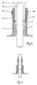
- the device according to the invention is delivered to fitter in the form illustrated in Figure 2.
- This device comprises a support on which is threaded said sealing sheath 6, said support being constituted by a first tube 8 intended to be fixed on the chimney 4 as illustrated by the figure 3.
- a second tube 10 is fitted onto the first tube 8, and a traction member 12 is provided for extracting the second tube 10 of the sealing sheath 6 when the electric wire 14 is introduced into the box through said support.
- the chimney 4 is closed. Its opening is made by sawing its end higher. This may result in smearing of sawn timber which can damage the sealing sheath 6. Also, the first tube 8 which remains in place around the chimney 4 protects the sealing sheath 6 against any mechanical attack due to possible saw burrs.
- the traction member 12 is constituted by a flexible film interposed between the outer surface of the second tube 10 and the inner surface of the sheath sealing 6. This film passes through the nesting zone of the second tube 10 on the first tube 8 to come out through the interior of said second tube 10 with a length sufficient to constitute a tongue intended to be pulled to extract this second tube 10 of the sealing sheath 6.
- a sealing ring 20 in adhesive material is interposed between said flexible film 12 and the inner surface of the sealing sheath 6.
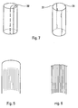
- the film surface can be cut into lamellae.
- this second tube 10 is separated into at at least two parts so as to separate it from the wire electric 14.
- the second tube 10 is preferably constituted by two half-cylinders 22, 24 associated mechanically, by interlocking for example as shown in Figure 7.
- the second tube 10 is split by tearing off a tongue of cutout 30.
Abstract
Description
La présente invention concerne un dispositif et un procédé de fixation et de rétreint d'une gaine d'étanchéité mécanico-rétractable sur une cheminée d'entrée d'un fil électrique dans un coffret électrique.The present invention relates to a device and a method of fixing and shrinking a sheath mechanically retractable sealing on a chimney entry of an electric wire into an electrical box.
L'invention concerne un dispositif et un procédé de fixation sur un coffret électrique des fils électriques unipolaires constituant un câble multipolaire.The invention relates to a device and a method. for fixing wires to an electrical box unipolar electrical cables multipolar.
Les dispositifs de l'art antérieur utilisés pour
fixer un fil électrique dans un coffret électrique sont
complexes et nécessitent de ce fait une grande habilité
de la part de l'opérateur. Par exemple, le document FR 2
623 344, qui représente l'état de la technique le plus proche, décrit un dispositif de raccordement étanche d'un
câble électrique à un coffret comportant une enveloppe
rigige entourant l'extrémité du câble et destinée à être
remplie d'une résine d'étanchéité.The devices of the prior art used for
fix an electric wire in an electrical box are
complex and therefore require great skill
from the operator. For example,
On connaít par ailleurs des dispositifs utilisant des gaines thermo-rétractables placées à cheval sur le câble et sur la cheminée d'entrée de câble. Dans ce type de dispositif, après introduction du fil dans la cheminée, la gaine est chauffée pour venir enserrer simultanément le fil et la cheminée. Ladite gaine comportant à cet effet un enduit thermo-fusible qui assure l'adhérence de la gaine sur le fil.We also know devices using heat-shrink sleeves placed astride the cable and on the cable entry chimney. In this type of device, after introduction of the wire into the chimney, the sheath is heated to enclose simultaneously the wire and the chimney. Said sheath comprising for this purpose a heat-fusible coating which ensures the grip of the sheath on the wire.
Ces dispositifs sont complexes et nécessitent un temps de montage trop long qui dépend de l'habilité de l'opérateur.These devices are complex and require assembly time too long which depends on the skill of the operator.
Le but de l'invention est de pallier les inconvénients ci-dessus.The object of the invention is to overcome the disadvantages above.
A cet effet, le dispositif selon l'invention est caractérisé en ce qu'il comporte un support sur lequel est prévue ladite gaine d'étanchéité, ledit support étant constitué par un premier tube destiné à venir se fixer sur la cheminée d'entrée du fil électrique et un deuxième tube emboíté sur ledit premier tube, un organe de traction étant prévu pour extraire le deuxième tube de la gaine d'étanchéité lorsque le fil est introduit dans le coffret à travers ledit support de telle sorte que la gaine d'étanchéité vienne enserrer ensemble le fil électrique, le premier tube et la cheminée.To this end, the device according to the invention is characterized in that it comprises a support on which said sealing sheath is provided, said support being consisting of a first tube intended to be fixed on the entry chimney of the electric wire and a second tube fitted on said first tube, a member being provided to extract the second tube from the sealing sheath when the wire is introduced into the cabinet through said support so that the sealing sheath grips the wire together electric, the first tube and the chimney.
Le dispositif selon l'invention permet ainsi de simplifier la pose de la gaine sur la cheminée d'entrée du câble et de réduire le temps nécessaire pour effectuer ce montage.The device according to the invention thus makes it possible to simplify the installation of the sheath on the entry chimney of the cable and reduce the time required to perform this mounting.
Préférentiellement, l'organe de traction est constitué par un film souple intercalé entre la surface extérieure du deuxième tube et la surface intérieure de la gaine d'étanchéité et traversant la zone d'emboítement du deuxième tube sur le premier tube pour ressortir par l'intérieur dudit deuxième tube avec une longueur suffisante de manière à constituer une languette destinée à être tirée pour extraire le deuxième tube de ladite gaine d'étanchéité.Preferably, the traction member is constituted by a flexible film interposed between the surface outer of the second tube and the inner surface of the sealing sheath and passing through the socket area of the second tube on the first tube to come out through the inside of said second tube with a length sufficient to constitute a tongue intended to be pulled to extract the second tube from said sealing sheath.
Le procédé selon l'invention est caractérisé en ce que l'on fixe sur la cheminée d'entrée du fil un support sensiblement tubulaire entouré par la gaine d'étanchéité et comportant un premier tube et au moins un deuxième emboíté sur le premier tube, on introduit le câble à travers le support, puis on extrait le deuxième tube de la gaine de telle sorte que celle-ci vienne enserrer ensemble le fil électrique, le premier tube et ladite cheminée.The method according to the invention is characterized in what we fix on the wire entry chimney a substantially tubular support surrounded by the sheath sealing and comprising a first tube and at least one second fitted on the first tube, we introduce the cable through the support, then we extract the second sheath tube so that it comes grip together the electric wire, the first tube and said chimney.
D'autres caractéristiques et avantages de l'invention ressortiront de la description qui va suivre, prise à titre d'exemple non limitatif, en référence aux figures annexées dans lesquelles:
- la figure 1 illustre schématiquement trois plaques amovibles destinées chacune à recevoir un câble tétrapolaire;
- la figure 2 représente une vue schématique en coupe verticale d'un dispositif selon l'invention ;
- la figure 3 représente une vue partielle d'un dispositif selon l'invention avant son installation sur un coffret électrique ;
- la figure 4 représente schématiquement et partiellement un dispositif selon l'invention fixé sur un coffret électrique.
- la figure 5 illustre un premier mode de réalisation d'un film souple équipant le dispositif de la figure 3 ;
- la figure 6 illustre un deuxième mode de réalisation d'un film souple équipant le dispositif de la figure 4 ;
- la figure 7 représente deux modes de réalisation du deuxième tube faisant partie du dispositif selon l'invention.
- Figure 1 schematically illustrates three removable plates each for receiving a four-pole cable;
- FIG. 2 represents a schematic view in vertical section of a device according to the invention;
- FIG. 3 represents a partial view of a device according to the invention before its installation on an electrical box;
- Figure 4 shows schematically and partially a device according to the invention fixed on an electrical box.
- Figure 5 illustrates a first embodiment of a flexible film fitted to the device of Figure 3;
- Figure 6 illustrates a second embodiment of a flexible film fitted to the device of Figure 4;
- FIG. 7 shows two embodiments of the second tube forming part of the device according to the invention.
La figure 1 représente trois plaques amovibles 2
comportant chacune quatre cheminées 4 d'entrées de fil
conducteur unipolaire à introduire dans le coffret.Figure 1 shows three
Le dispositif selon l'invention est livré au
monteur sous la forme illustrée par la figure 2. Ce
dispositif comporte un support sur lequel est enfilée
ladite gaine d'étanchéité 6, ledit support étant
constitué par un premier tube 8 destiné à venir se fixer
sur la cheminée 4 comme cela est illustré par la figure
3. Un deuxième tube 10 est emboíté sur le premier tube
8, et un organe de traction 12 est prévu pour extraire
le deuxième tube 10 de la gaine d'étanchéité 6 lorsque
le fil électrique 14 est introduit dans le coffret à
travers ledit support.The device according to the invention is delivered to
fitter in the form illustrated in Figure 2. This
device comprises a support on which is threaded
said sealing
Comme cela est représenté à la figure 4, après
extraction du deuxième tube 10, la gaine d'étanchéité 6
vient enserrer ensemble le fil électrique 14, le premier
tube 8 et la cheminée 4.As shown in Figure 4, after
extraction of the
Généralement, lorsqu'aucun fil n'est introduit
dans le coffret électrique, la cheminée 4 est obturée.
Son ouverture est réalisée par sciage de son extrémité
supérieure. Il peut en résulter alors des bavures de
sciages qui peuvent endommager la gaine d'étanchéité 6.
Aussi, le premier tube 8 qui reste en place autour de
la cheminée 4 permet de protéger la gaine d'étanchéité 6
contre toute agression mécanique due à d'éventuelles
bavures de sciage.Generally, when no wire is introduced
in the electrical box, the
Selon un mode préféré de réalisation de
l'invention, l'organe de traction 12 est constitué par
un film souple intercalé entre la surface extérieure du
deuxième tube 10 et la surface intérieure de la gaine
d'étanchéité 6. Ce film traverse la zone d'emboítement
du deuxième tube 10 sur le premier tube 8 pour ressortir
par l'intérieur dudit deuxième tube 10 avec une longueur
suffisante de manière à constituer une languette
destinée à être tirée pour extraire ce deuxième tube 10
de la gaine d'étanchéité 6. Un anneau d'étanchéité 20 en
matériau adhésif est intercalé entre ledit film souple
12 et la surface intérieure de la gaine d'étanchéité 6.According to a preferred embodiment of
the invention, the
Lors de l'extraction du deuxième tube 10 de la
gaine d'étanchéité 6 par traction sur le film souple 12,
ce dernier doit, sans bouger relativement à la gaine
d'étanchéité 6, glisser à l'intérieur du deuxième tube
10 pendant que celui-ci monte vers l'extérieur de la
gaine 6. Le film 12 doit donc glisser sur le bord
inférieur du deuxième tube 10 sans faire de plis. Pour
cela, la surface du film souple 12 est pliée en
accordéon comme cela est illustré par la figure 5.When extracting the
Dans un autre mode de réalisation illustré par la figure 6, la surface du film peut être découpée en lamelles. In another embodiment illustrated by Figure 6, the film surface can be cut into lamellae.
Après extraction du deuxième tube de la gaine
d'étanchéité 6, on sépare ce deuxième tube 10 en au
moins deux parties de manière à le désolidariser du fil
électrique 14.After extraction of the second tube from the
Pour faciliter cette séparation, le deuxième
tube 10 est préférentiellement constitué par deux demi-cylindres
22, 24 associés mécaniquement, par emboítement
par exemple comme cela est illustré par la figure 7.To facilitate this separation, the
Dans un autre mode de réalisation, le deuxième
tube 10 est fendu par arrachage d'une languette de
découpe 30.In another embodiment, the
Claims (8)
- Device for fixing and shrinking a mechanically shrinkable sealing sleeve (6) onto an input shaft (4) for an electrical wire in an electrical box, characterized in that it comprises a support on which the sealing sleeve (6) is provided, the said support being formed by a first tube (8), intended to be fixed onto the said shaft (4), and a second tube (10) fitted over the first tube (8), a pulling member (12) is provided, in order to extract the second tube (10) from the sealing sleeve (6) when the electrical wire (14) is introduced into the box through the said support, in such a way that the sealing sleeve (6) grips the electrical wire (14), the first tube (8) and the shaft (4) together.
- Device according to Claim 1, characterized in that the pulling member (12) is formed by a flexible film inserted between the outer surface of the second tube (10) and the inner surface of the sealing sleeve (6) and passing through the region where the second tube (10) fits over the first tube (8) before re-emerging via the inside of the said second tube (10) with a sufficient length, so as to constitute a tab intended to be pulled in order to remove the second tube (10) from the sealing sleeve (6).
- Device according to Claim 2, characterized in that it furthermore includes an adhesive sealing ring (20) inserted between the said flexible film (12) and the inner surface of the sealing sleeve (6).
- Device according to Claim 3, characterized in that the surface of the flexible film (12) is folded in the manner of a concertina.
- Device according to Claim 3, characterized in that the surface of the flexible film (12) is slit into strips.
- Device according to one of Claims 1 to 5, characterized in that the second tube (10) comprises at least two half-cylinders (22, 24) intended to be separated after the said second tube (10) has been removed from the sealing sleeve (6).
- Method of mounting a mechanically shrinkable sealing sleeve (6) onto an input shaft (4) for an electrical wire (14) in an electrical box, characterized in that a substantially tubular support, surrounded by the sealing sleeve (6) and comprising a first tube (8) and at least a second tube (10) fitted over the first tube (8), is fixed onto the shaft (4), the wire (14) is introduced through the support and then the second tube (10) is extracted from the sleeve (6) in such a way that the latter grips the said wire (14), the said first tube (8) and the shaft (4).
- Method according to Claim 7, characterized in that, after the second tube (10) has been removed, this second tube (10) is separated into at least two parts so as to disconnect it from the electrical cable.
Applications Claiming Priority (3)
| Application Number | Priority Date | Filing Date | Title |
|---|---|---|---|
| FR0000606A FR2803953B1 (en) | 2000-01-18 | 2000-01-18 | DEVICE AND METHOD FOR FIXING AND RETAINING A MULTIPOLAR CABLE IN AN ELECTRICAL BOX |
| FR0000606 | 2000-01-18 | ||
| PCT/FR2001/000046 WO2001054244A1 (en) | 2000-01-18 | 2001-01-08 | Device and method for fixing and shrinking a multipole cable in an electrical box |
Publications (2)
| Publication Number | Publication Date |
|---|---|
| EP1249059A1 EP1249059A1 (en) | 2002-10-16 |
| EP1249059B1 true EP1249059B1 (en) | 2003-06-25 |
Family
ID=8846029
Family Applications (1)
| Application Number | Title | Priority Date | Filing Date |
|---|---|---|---|
| EP01903887A Expired - Lifetime EP1249059B1 (en) | 2000-01-18 | 2001-01-08 | Device and method for fixing and shrinking a multipole cable in an electrical box |
Country Status (8)
| Country | Link |
|---|---|
| EP (1) | EP1249059B1 (en) |
| AT (1) | ATE243890T1 (en) |
| AU (1) | AU2001231852A1 (en) |
| DE (1) | DE60100402D1 (en) |
| ES (1) | ES2202272T3 (en) |
| FR (1) | FR2803953B1 (en) |
| PT (1) | PT1249059E (en) |
| WO (1) | WO2001054244A1 (en) |
Families Citing this family (1)
| Publication number | Priority date | Publication date | Assignee | Title |
|---|---|---|---|---|
| FR3048312B1 (en) * | 2016-02-26 | 2019-11-15 | Michaud Sa | INSULATING SLEEVE FOR ONE END OF A CABLE |
Family Cites Families (4)
| Publication number | Priority date | Publication date | Assignee | Title |
|---|---|---|---|---|
| DE7516723U (en) * | 1975-05-26 | 1977-02-17 | Siemens Ag, 1000 Berlin Und 8000 Muenchen | Arrangement for the introduction of cables in cable sleeves |
| FR2623344B1 (en) * | 1987-11-18 | 1993-01-29 | Seram | DEVICE FOR SEALED CONNECTION OF AN ELECTRICAL CABLE TO A BOX |
| US4983784A (en) * | 1988-05-13 | 1991-01-08 | Whitlock Ronald K | Cable termination apparatus and method |
| DE9417983U1 (en) * | 1994-11-10 | 1994-12-22 | Kabelmetal Electro Gmbh | Arrangement for sealing an annular gap |
-
2000
- 2000-01-18 FR FR0000606A patent/FR2803953B1/en not_active Expired - Fee Related
-
2001
- 2001-01-08 EP EP01903887A patent/EP1249059B1/en not_active Expired - Lifetime
- 2001-01-08 AU AU2001231852A patent/AU2001231852A1/en not_active Abandoned
- 2001-01-08 WO PCT/FR2001/000046 patent/WO2001054244A1/en active IP Right Grant
- 2001-01-08 PT PT01903887T patent/PT1249059E/en unknown
- 2001-01-08 DE DE60100402T patent/DE60100402D1/en not_active Expired - Lifetime
- 2001-01-08 ES ES01903887T patent/ES2202272T3/en not_active Expired - Lifetime
- 2001-01-08 AT AT01903887T patent/ATE243890T1/en not_active IP Right Cessation
Also Published As
| Publication number | Publication date |
|---|---|
| FR2803953B1 (en) | 2002-03-08 |
| EP1249059A1 (en) | 2002-10-16 |
| DE60100402D1 (en) | 2003-07-31 |
| ATE243890T1 (en) | 2003-07-15 |
| AU2001231852A1 (en) | 2001-07-31 |
| PT1249059E (en) | 2003-11-28 |
| ES2202272T3 (en) | 2004-04-01 |
| FR2803953A1 (en) | 2001-07-20 |
| WO2001054244A1 (en) | 2001-07-26 |
Similar Documents
| Publication | Publication Date | Title |
|---|---|---|
| EP0504035A2 (en) | Connecting device for one or two power cables, and process for mounting this device at the end of the cables | |
| EP1004153B1 (en) | Electric connection device with fluid insulator | |
| EP0202972A1 (en) | Sleeve for protecting an electrical junction between an underground cable and an overhead cable insulated at a low voltage | |
| EP1249059B1 (en) | Device and method for fixing and shrinking a multipole cable in an electrical box | |
| EP1383211B1 (en) | Method for crimping a contact to strands of a cable | |
| EP0593344B1 (en) | Connecting system for the housings of two devices of which at least one is under pressure | |
| EP0595708B1 (en) | Device avoiding insulation shrinkage for power cables with synthetic insulation | |
| EP1860672A1 (en) | Bushing assembly designed to be mounted through an orifice in the wall of an electricity transformer | |
| EP0933856B1 (en) | Cold shrinkable sealing sleeve for electrical cable | |
| EP0797281B1 (en) | Process and assembly for mounting tightly a resilient tubular covering on an element | |
| EP0844719B1 (en) | Device for protecting cablejunctions | |
| FR3068422A1 (en) | DEVICE AND METHOD FOR VOLTAGE LOCKING A CABLE USING A GREEN-CABLE CLAMP | |
| EP0732768B1 (en) | Process for making an electrical connection to a metallic screen of a power cable and ring for carrying out the process | |
| FR2653609A1 (en) | CUFF TYPE SEALING ELEMENT. | |
| CA2652684C (en) | Assembly to enclose interiorly a long element with a protective elastic sleeve | |
| FR2466887A1 (en) | Sealing plug for cable duct - has plastics plug pushed into cable duct and when cable is to be run plug end is snapped out | |
| FR2716579A1 (en) | Electrical connection device for conductive cable screens, and method for its implementation. | |
| EP0862801B1 (en) | Electrical coupling part | |
| FR2685141A1 (en) | JUNCTION OF ELECTRIC CABLES, PREFERRED JUNCTION ASSEMBLY AND METHOD FOR IMPLEMENTING THE SAME. | |
| EP0963022B1 (en) | Method and device for placing a tubular element on a receiving part and corresponding assembly | |
| FR3048312B1 (en) | INSULATING SLEEVE FOR ONE END OF A CABLE | |
| FR2551927A1 (en) | Electromagnetic-screening device for a joint | |
| FR2586865A1 (en) | Electrical connection lug, especially for external installations | |
| FR3104838A1 (en) | Protection set for at least one cable | |
| BE394660A (en) |
Legal Events
| Date | Code | Title | Description |
|---|---|---|---|
| PUAI | Public reference made under article 153(3) epc to a published international application that has entered the european phase |
Free format text: ORIGINAL CODE: 0009012 |
|
| 17P | Request for examination filed |
Effective date: 20020704 |
|
| AK | Designated contracting states |
Kind code of ref document: A1 Designated state(s): AT BE CH CY DE DK ES FI FR GB GR IE IT LI LU MC NL PT SE TR |
|
| AX | Request for extension of the european patent |
Free format text: AL;LT;LV;MK;RO;SI |
|
| RIN1 | Information on inventor provided before grant (corrected) |
Inventor name: GAILLARD, LAURENT Inventor name: VINCENT-FRANCES, HELENE |
|
| GRAH | Despatch of communication of intention to grant a patent |
Free format text: ORIGINAL CODE: EPIDOS IGRA |
|
| GRAH | Despatch of communication of intention to grant a patent |
Free format text: ORIGINAL CODE: EPIDOS IGRA |
|
| GRAA | (expected) grant |
Free format text: ORIGINAL CODE: 0009210 |
|
| AK | Designated contracting states |
Designated state(s): AT BE CH CY DE DK ES FI FR GB GR IE IT LI LU MC NL PT SE TR |
|
| PG25 | Lapsed in a contracting state [announced via postgrant information from national office to epo] |
Ref country code: IT Free format text: LAPSE BECAUSE OF FAILURE TO SUBMIT A TRANSLATION OF THE DESCRIPTION OR TO PAY THE FEE WITHIN THE PRE;WARNING: LAPSES OF ITALIAN PATENTS WITH EFFECTIVE DATE BEFORE 2007 MAY HAVE OCCURRED AT ANY TIME BEFORE 2007. THE CORRECT EFFECTIVE DATE MAY BE DIFFERENT FROM THE ONE RECORDED.SCRIBED TIME-LIMIT Effective date: 20030625 Ref country code: CY Free format text: LAPSE BECAUSE OF FAILURE TO SUBMIT A TRANSLATION OF THE DESCRIPTION OR TO PAY THE FEE WITHIN THE PRESCRIBED TIME-LIMIT Effective date: 20030625 Ref country code: NL Free format text: LAPSE BECAUSE OF FAILURE TO SUBMIT A TRANSLATION OF THE DESCRIPTION OR TO PAY THE FEE WITHIN THE PRESCRIBED TIME-LIMIT Effective date: 20030625 Ref country code: GB Free format text: LAPSE BECAUSE OF FAILURE TO SUBMIT A TRANSLATION OF THE DESCRIPTION OR TO PAY THE FEE WITHIN THE PRESCRIBED TIME-LIMIT Effective date: 20030625 Ref country code: AT Free format text: LAPSE BECAUSE OF FAILURE TO SUBMIT A TRANSLATION OF THE DESCRIPTION OR TO PAY THE FEE WITHIN THE PRESCRIBED TIME-LIMIT Effective date: 20030625 Ref country code: FI Free format text: LAPSE BECAUSE OF FAILURE TO SUBMIT A TRANSLATION OF THE DESCRIPTION OR TO PAY THE FEE WITHIN THE PRESCRIBED TIME-LIMIT Effective date: 20030625 Ref country code: TR Free format text: LAPSE BECAUSE OF FAILURE TO SUBMIT A TRANSLATION OF THE DESCRIPTION OR TO PAY THE FEE WITHIN THE PRESCRIBED TIME-LIMIT Effective date: 20030625 Ref country code: IE Free format text: LAPSE BECAUSE OF FAILURE TO SUBMIT A TRANSLATION OF THE DESCRIPTION OR TO PAY THE FEE WITHIN THE PRESCRIBED TIME-LIMIT Effective date: 20030625 |
|
| REG | Reference to a national code |
Ref country code: GB Ref legal event code: FG4D Free format text: NOT ENGLISH |
|
| REG | Reference to a national code |
Ref country code: CH Ref legal event code: EP |
|
| REG | Reference to a national code |
Ref country code: IE Ref legal event code: FG4D Free format text: FRENCH |
|
| REF | Corresponds to: |
Ref document number: 60100402 Country of ref document: DE Date of ref document: 20030731 Kind code of ref document: P |
|
| PG25 | Lapsed in a contracting state [announced via postgrant information from national office to epo] |
Ref country code: GR Free format text: LAPSE BECAUSE OF FAILURE TO SUBMIT A TRANSLATION OF THE DESCRIPTION OR TO PAY THE FEE WITHIN THE PRESCRIBED TIME-LIMIT Effective date: 20030925 Ref country code: SE Free format text: LAPSE BECAUSE OF FAILURE TO SUBMIT A TRANSLATION OF THE DESCRIPTION OR TO PAY THE FEE WITHIN THE PRESCRIBED TIME-LIMIT Effective date: 20030925 Ref country code: DK Free format text: LAPSE BECAUSE OF FAILURE TO SUBMIT A TRANSLATION OF THE DESCRIPTION OR TO PAY THE FEE WITHIN THE PRESCRIBED TIME-LIMIT Effective date: 20030925 |
|
| PG25 | Lapsed in a contracting state [announced via postgrant information from national office to epo] |
Ref country code: DE Free format text: LAPSE BECAUSE OF FAILURE TO SUBMIT A TRANSLATION OF THE DESCRIPTION OR TO PAY THE FEE WITHIN THE PRESCRIBED TIME-LIMIT Effective date: 20030926 |
|
| LTIE | Lt: invalidation of european patent or patent extension |
Effective date: 20030625 |
|
| NLV1 | Nl: lapsed or annulled due to failure to fulfill the requirements of art. 29p and 29m of the patents act | ||
| GBV | Gb: ep patent (uk) treated as always having been void in accordance with gb section 77(7)/1977 [no translation filed] |
Effective date: 20030625 |
|
| PG25 | Lapsed in a contracting state [announced via postgrant information from national office to epo] |
Ref country code: LU Free format text: LAPSE BECAUSE OF NON-PAYMENT OF DUE FEES Effective date: 20040108 |
|
| PG25 | Lapsed in a contracting state [announced via postgrant information from national office to epo] |
Ref country code: MC Free format text: LAPSE BECAUSE OF NON-PAYMENT OF DUE FEES Effective date: 20040131 Ref country code: BE Free format text: LAPSE BECAUSE OF NON-PAYMENT OF DUE FEES Effective date: 20040131 |
|
| REG | Reference to a national code |
Ref country code: IE Ref legal event code: FD4D |
|
| REG | Reference to a national code |
Ref country code: ES Ref legal event code: FG2A Ref document number: 2202272 Country of ref document: ES Kind code of ref document: T3 |
|
| PLBE | No opposition filed within time limit |
Free format text: ORIGINAL CODE: 0009261 |
|
| STAA | Information on the status of an ep patent application or granted ep patent |
Free format text: STATUS: NO OPPOSITION FILED WITHIN TIME LIMIT |
|
| 26N | No opposition filed |
Effective date: 20040326 |
|
| BERE | Be: lapsed |
Owner name: MANUFACTURE D'APPAREILLAGE ELECTRIQUE DE CAHORS - Effective date: 20040131 |
|
| PG25 | Lapsed in a contracting state [announced via postgrant information from national office to epo] |
Ref country code: FR Free format text: LAPSE BECAUSE OF NON-PAYMENT OF DUE FEES Effective date: 20040930 |
|
| REG | Reference to a national code |
Ref country code: FR Ref legal event code: ST |
|
| PG25 | Lapsed in a contracting state [announced via postgrant information from national office to epo] |
Ref country code: CH Free format text: LAPSE BECAUSE OF NON-PAYMENT OF DUE FEES Effective date: 20050131 Ref country code: LI Free format text: LAPSE BECAUSE OF NON-PAYMENT OF DUE FEES Effective date: 20050131 |
|
| REG | Reference to a national code |
Ref country code: CH Ref legal event code: PL |
|
| REG | Reference to a national code |
Ref country code: PT Ref legal event code: PC4A Owner name: MANUFACTURE D'APPAREILLAGE ELECTRIQUE DE CAHOR, FR Effective date: 20060622 |
|
| PGFP | Annual fee paid to national office [announced via postgrant information from national office to epo] |
Ref country code: ES Payment date: 20080218 Year of fee payment: 8 |
|
| PGFP | Annual fee paid to national office [announced via postgrant information from national office to epo] |
Ref country code: PT Payment date: 20080107 Year of fee payment: 8 |
|
| REG | Reference to a national code |
Ref country code: PT Ref legal event code: MM4A Free format text: LAPSE DUE TO NON-PAYMENT OF FEES Effective date: 20090708 |
|
| PG25 | Lapsed in a contracting state [announced via postgrant information from national office to epo] |
Ref country code: PT Free format text: LAPSE BECAUSE OF NON-PAYMENT OF DUE FEES Effective date: 20090708 |
|
| REG | Reference to a national code |
Ref country code: ES Ref legal event code: FD2A Effective date: 20090109 |
|
| PG25 | Lapsed in a contracting state [announced via postgrant information from national office to epo] |
Ref country code: ES Free format text: LAPSE BECAUSE OF NON-PAYMENT OF DUE FEES Effective date: 20090109 |