EP1248318A2 - Electrical contact as well as lamphoder and connecting terminal with at least such a contact - Google Patents
Electrical contact as well as lamphoder and connecting terminal with at least such a contact Download PDFInfo
- Publication number
- EP1248318A2 EP1248318A2 EP02004723A EP02004723A EP1248318A2 EP 1248318 A2 EP1248318 A2 EP 1248318A2 EP 02004723 A EP02004723 A EP 02004723A EP 02004723 A EP02004723 A EP 02004723A EP 1248318 A2 EP1248318 A2 EP 1248318A2
- Authority
- EP
- European Patent Office
- Prior art keywords
- contact
- spring
- contact spring
- base section
- section
- Prior art date
- Legal status (The legal status is an assumption and is not a legal conclusion. Google has not performed a legal analysis and makes no representation as to the accuracy of the status listed.)
- Granted
Links
- 229910052736 halogen Inorganic materials 0.000 claims abstract description 12
- 150000002367 halogens Chemical class 0.000 claims abstract description 12
- 239000011810 insulating material Substances 0.000 claims abstract description 5
- 239000004020 conductor Substances 0.000 claims description 24
- 238000003780 insertion Methods 0.000 claims description 7
- 230000037431 insertion Effects 0.000 claims description 7
- 239000002184 metal Substances 0.000 claims description 5
- 229910052751 metal Inorganic materials 0.000 claims description 5
- 238000004873 anchoring Methods 0.000 claims description 2
- 238000005452 bending Methods 0.000 description 4
- 239000000463 material Substances 0.000 description 4
- 238000009434 installation Methods 0.000 description 3
- RYGMFSIKBFXOCR-UHFFFAOYSA-N Copper Chemical group [Cu] RYGMFSIKBFXOCR-UHFFFAOYSA-N 0.000 description 2
- 229910000831 Steel Inorganic materials 0.000 description 2
- 239000012212 insulator Substances 0.000 description 2
- 229910052759 nickel Inorganic materials 0.000 description 2
- PXHVJJICTQNCMI-UHFFFAOYSA-N nickel Substances [Ni] PXHVJJICTQNCMI-UHFFFAOYSA-N 0.000 description 2
- 239000010959 steel Substances 0.000 description 2
- VNNRSPGTAMTISX-UHFFFAOYSA-N chromium nickel Chemical compound [Cr].[Ni] VNNRSPGTAMTISX-UHFFFAOYSA-N 0.000 description 1
- 238000010276 construction Methods 0.000 description 1
- 229910052802 copper Inorganic materials 0.000 description 1
- 239000010949 copper Substances 0.000 description 1
- 238000002347 injection Methods 0.000 description 1
- 239000007924 injection Substances 0.000 description 1
- 230000010354 integration Effects 0.000 description 1
- 230000003993 interaction Effects 0.000 description 1
- 238000002955 isolation Methods 0.000 description 1
- 230000014759 maintenance of location Effects 0.000 description 1
- 238000004519 manufacturing process Methods 0.000 description 1
- 239000000243 solution Substances 0.000 description 1
- 238000009966 trimming Methods 0.000 description 1
Images


Classifications
-
- H—ELECTRICITY
- H01—ELECTRIC ELEMENTS
- H01R—ELECTRICALLY-CONDUCTIVE CONNECTIONS; STRUCTURAL ASSOCIATIONS OF A PLURALITY OF MUTUALLY-INSULATED ELECTRICAL CONNECTING ELEMENTS; COUPLING DEVICES; CURRENT COLLECTORS
- H01R33/00—Coupling devices specially adapted for supporting apparatus and having one part acting as a holder providing support and electrical connection via a counterpart which is structurally associated with the apparatus, e.g. lamp holders; Separate parts thereof
- H01R33/05—Two-pole devices
- H01R33/06—Two-pole devices with two current-carrying pins, blades or analogous contacts, having their axes parallel to each other
-
- H—ELECTRICITY
- H01—ELECTRIC ELEMENTS
- H01R—ELECTRICALLY-CONDUCTIVE CONNECTIONS; STRUCTURAL ASSOCIATIONS OF A PLURALITY OF MUTUALLY-INSULATED ELECTRICAL CONNECTING ELEMENTS; COUPLING DEVICES; CURRENT COLLECTORS
- H01R4/00—Electrically-conductive connections between two or more conductive members in direct contact, i.e. touching one another; Means for effecting or maintaining such contact; Electrically-conductive connections having two or more spaced connecting locations for conductors and using contact members penetrating insulation
- H01R4/28—Clamped connections, spring connections
- H01R4/48—Clamped connections, spring connections utilising a spring, clip, or other resilient member
- H01R4/4809—Clamped connections, spring connections utilising a spring, clip, or other resilient member using a leaf spring to bias the conductor toward the busbar
- H01R4/4846—Busbar details
- H01R4/485—Single busbar common to multiple springs
-
- H—ELECTRICITY
- H01—ELECTRIC ELEMENTS
- H01R—ELECTRICALLY-CONDUCTIVE CONNECTIONS; STRUCTURAL ASSOCIATIONS OF A PLURALITY OF MUTUALLY-INSULATED ELECTRICAL CONNECTING ELEMENTS; COUPLING DEVICES; CURRENT COLLECTORS
- H01R13/00—Details of coupling devices of the kinds covered by groups H01R12/70 or H01R24/00 - H01R33/00
- H01R13/02—Contact members
- H01R13/10—Sockets for co-operation with pins or blades
- H01R13/11—Resilient sockets
-
- H—ELECTRICITY
- H01—ELECTRIC ELEMENTS
- H01R—ELECTRICALLY-CONDUCTIVE CONNECTIONS; STRUCTURAL ASSOCIATIONS OF A PLURALITY OF MUTUALLY-INSULATED ELECTRICAL CONNECTING ELEMENTS; COUPLING DEVICES; CURRENT COLLECTORS
- H01R4/00—Electrically-conductive connections between two or more conductive members in direct contact, i.e. touching one another; Means for effecting or maintaining such contact; Electrically-conductive connections having two or more spaced connecting locations for conductors and using contact members penetrating insulation
- H01R4/28—Clamped connections, spring connections
- H01R4/48—Clamped connections, spring connections utilising a spring, clip, or other resilient member
- H01R4/4809—Clamped connections, spring connections utilising a spring, clip, or other resilient member using a leaf spring to bias the conductor toward the busbar
- H01R4/48185—Clamped connections, spring connections utilising a spring, clip, or other resilient member using a leaf spring to bias the conductor toward the busbar adapted for axial insertion of a wire end
- H01R4/4819—Clamped connections, spring connections utilising a spring, clip, or other resilient member using a leaf spring to bias the conductor toward the busbar adapted for axial insertion of a wire end the spring shape allowing insertion of the conductor end when the spring is unbiased
- H01R4/4821—Single-blade spring
-
- H—ELECTRICITY
- H01—ELECTRIC ELEMENTS
- H01R—ELECTRICALLY-CONDUCTIVE CONNECTIONS; STRUCTURAL ASSOCIATIONS OF A PLURALITY OF MUTUALLY-INSULATED ELECTRICAL CONNECTING ELEMENTS; COUPLING DEVICES; CURRENT COLLECTORS
- H01R4/00—Electrically-conductive connections between two or more conductive members in direct contact, i.e. touching one another; Means for effecting or maintaining such contact; Electrically-conductive connections having two or more spaced connecting locations for conductors and using contact members penetrating insulation
- H01R4/28—Clamped connections, spring connections
- H01R4/48—Clamped connections, spring connections utilising a spring, clip, or other resilient member
- H01R4/4809—Clamped connections, spring connections utilising a spring, clip, or other resilient member using a leaf spring to bias the conductor toward the busbar
- H01R4/484—Spring housing details
-
- H—ELECTRICITY
- H01—ELECTRIC ELEMENTS
- H01R—ELECTRICALLY-CONDUCTIVE CONNECTIONS; STRUCTURAL ASSOCIATIONS OF A PLURALITY OF MUTUALLY-INSULATED ELECTRICAL CONNECTING ELEMENTS; COUPLING DEVICES; CURRENT COLLECTORS
- H01R4/00—Electrically-conductive connections between two or more conductive members in direct contact, i.e. touching one another; Means for effecting or maintaining such contact; Electrically-conductive connections having two or more spaced connecting locations for conductors and using contact members penetrating insulation
- H01R4/70—Insulation of connections
- H01R4/72—Insulation of connections using a heat shrinking insulating sleeve
Definitions
- the invention first relates to an electrical contact, especially for lamp holders, connection or distribution terminals or the like.
- an electrical contact especially for lamp holders, connection or distribution terminals or the like.
- electrical conductors such as wires or Contact pins
- the contact body forms a kind of frame component on which the contact spring is held, and wherein between at least one inner surface of the Contact body and contact sections of the contact spring contact zones are formed according to the preamble of claim 1.
- DE 93 09 139 U1 shows and describes a lamp holder for Halogen lamps with a contact carrier made of insulating material and two so-called clamping contacts. Every terminal contact that does the job has the electrical connection between a connecting conductor and To manufacture a lamp contact pin is formed here in two parts. One part is box-shaped and is pressed into the insulating body, where he sits with the help of a barbed latch clawed against falling out. The one in the cavity of the box-shaped The first part inserted second part consists of a essentially S-shaped leaf spring. This shows itself in essentially straight extending end with a front Clamping edge and another bent end.
- the end with the clamping edge forms with the adjacent wall of the box-shaped Part of a screwless terminal for the stripped End of an electrical conductor to be inserted.
- the other, Round curved end serves to place the lamp contact pin between himself and the adjacent inner wall of the box-shaped body to contact by adhesion.
- the design of contacts consists of two parts to the extent that parts of different materials are used can be. So it is particularly recommended to use the contact spring e.g. to form from a chrome-nickel strip, the excellent Has spring properties even at high temperatures.
- the other part of the contact can e.g. be a copper part, which is characterized by optimal electrical conductivity and high mechanical Stability distinguishes.
- the two-part Terminal as it is the subject of DE 93 09 139 U1 advantageous.
- the terminals require a considerable amount of space. They are therefore suitable e.g. not for installation in halogen lamp sockets smaller diameter, such as for use in so-called trimmings with a Outside diameter of about 10 mm and an inside diameter of only approx. 8 mm are required.
- Such a halogen lamp holder is in DE 195 10 623 C2 shown and described. To make the necessary minor here. Mounting dimensions To ensure the contacts, they are relatively flat and crimped onto the stripped ends of the conductors. On in this way two relatively small contacts can be made in the same cross-sectional area of the socket body.
- the contact body is essentially U-shaped in cross section is that the contact spring has a base portion that is U-shaped of the contact body to form a tube and the contact sections the contact spring on the narrow ends of the elongated Base section are molded and from the same Extend the flat side of the base section away such that the two contact zones in the longitudinal direction of the contact one behind the other are arranged.
- the essential essence of the invention is therefore in Design of the contact as a tube contact with a small cross-sectional profile.
- the contact spring in not a cage-like one Contact body housed, but initially complements the essentially only U-shaped contact body to the tube contact. Consequently, the contact spring is not built into the contact body, but part of its scope.
- This idiosyncratic Construction allows the contact to be elongated can be extremely small in cross section.
- suitable Contacts of the type according to the invention for installation in insulating material socket bodies small diameter, especially for halogen lamp holders, for use in trimmed tubes or similar of 10 mm Diameters are suitable.
- This contact also approximated the shape of an im Cross-section of small tube, but remains over the entire length of the contact a longitudinal slot open, which increases the stability of the contact is low.
- there is all contact so be the portion representing the contact body as well as the Section forming contact springs from a one-piece component and consequently only from a single material, i.e. either e.g. Copper or e.g. Chromium-nickel steel. With such a contact the objectives of the invention cannot therefore be achieved.
- the elongated Base portion of the contact spring as a substantially flat strip formed, the ends of which slant towards the inside of the central Web of the U-shaped contact body are bent pointing.
- Another embodiment according to the invention provides that the U-legs of the contact body mounting tabs are molded to connect the contact spring to the contact body, wherein the the fastening tabs by reaching around the edge of the base portion of the contact spring on the contact body can set. By simply bending the fastening tabs the strip-shaped contact spring with the U-legs of the Contact body to an overall very stable and compact Contact element firmly connected.
- the Base section of the contact spring is provided with edge notches, into which the fastening tabs of the contact body are inserted.
- edge notches equal or only slightly is larger than the outer distance of the U-legs of the contact body from each other. The edge notches thus allow to a certain extent Way a "shape integration" of the contact spring in the contact body.
- Stability of the miniaturized contact is a feature advantageous which consists of the contact zones being in the same Cross-sectional areas of the contact are arranged like the fastening tabs.
- the highest possible load in the contact zones during operation exerts reaction forces exactly where the contact spring is fixed on the contact body. Those zones and areas who have no direct connection with each other will not strained and can therefore e.g. also do not bulge or deform in any other way.
- the arrangement of a lamp is preferably further made such that in an area between the contact zones from the Contact body released a stop tab and so in the Contact body is deformed into that with at least one of their narrow edges forms an insertion limit.
- notched and bent insertion limits are also in, for example US 4 084 876 A discloses.
- the respective leader meets vertically on the superscript wide area of the section and is thus directed transversely to its bending axis, whereas the peculiarity of the feature of the invention is that not wide area, but the narrow edge of the bent Stop tab forms the insertion limit.
- the material itself therefore does not need to absorb the resulting forces and can therefore be thin.
- the free ends of the contact sections of the contact spring essentially straight against the inside of the central web of the U-shaped Contact body pointing and each have a clamping edge for train a leader.
- Such contact would come in particular as or in a connection or connection terminal, as they are considered is described in principle in US 4,084,876 A and is used to two substantially axially opposite conductor ends take.
- Another embodiment provides that the end of the one contact section of the contact spring essentially straight against the inside of the central web of the U-shaped contact body runs in a pointing manner and forms a clamping edge for a conductor, while the other contact portion of the contact spring from one Bend is formed, one against the inside of the central web of the U-shaped contact body pointing Section leads away from the central web and a pressure contact zone for a contact pin such as lamp contact pin. The contact pin is then out of contact with a defined force can be pulled out again, so it is not clamped. That contact is ideal for installation e.g. in a halogen lamp holder.
- the invention relates to a lamp holder, in particular a halogen lamp socket comprising a socket body Made of insulating material with an elongated shaft and one with push-through openings for contact pins provided plate-like head and with channels for receiving contacts for connecting conductor ends for the power supply of the contact pins, the socket is characterized by contacts according to the invention.
- a contact that is used for anchoring in an insulator a barb-like from the base portion of the contact spring acting latch is cut out and shaped outwards, important if the locking tongue has a notch that the latch tab into a wider base and a narrower end tab divided so that the leading edge of the wider base one Stop for support on the reveal of a window in the Insulating body of the socket forms, in which only the narrower Can engage end tongue.
- the plug lock of the contact in the insulator the ensures that e.g. by pulling on the inserted conductor Locking tongue cannot deform and consequently also - even under increased pull-out forces - the contact does not come out of the insulating body can leak. This prevents a short to ground Isolation body surrounding trimmed tube.
- the invention also relates to a Terminal block using a contact with features according to the invention, the contact of is surrounded by a tubular insulating sheath, which is preferred is formed by a shrink tube.
- a contact designated 10 in its entirety is in two parts educated. It comprises a contact body 11 and a contact spring 12th
- the contact body 11 is made of a flat sheet metal blank 13 e.g. made of copper, essentially U-shaped, so that it defined three Sections, namely a U-web 14 and two to each other has parallel U-legs 15.
- the U-web 14 is not flat, but as e.g. out Fig. 1 can be seen, slightly curved outwards.
- Over the free ends of the U-legs 15 each project in pairs on two in the axial direction spaced areas mounting tabs 16, the Function is explained below.
- the contact spring 12 is made from a blank 17 in particular Chrome-nickel steel sheet shaped. It is divided into an im Cross section of flat rectangular and otherwise elongated base section 18, both ends of which are bent. The end section of the lower end 19 in FIG. 3 is essentially rectilinear, while the upper end 20 there still has a bend 22. This will be discussed later.
- the base section 18 of the contact spring 12 notches 22 on the arrangement and position of the fastening tabs 16 of the contact body 11 assigned. 5 and 6 clearly illustrate their Interaction, namely the edge engagement of the fastening tabs 16 in the edge notches 22 and reaching around bent mounting tabs 16 behind the back of the Base section 18 of the contact spring 12. As shown in FIGS. 5 and 6, is by this assembly of contact body 11 and Contact spring 12 a contact 10 closed all round created, which can be called a tube contact.
- the lower one runs in essential straight section 19 of the contact spring 12 obliquely against the rear inside 14a of the contact body 11 and forms together with this a screwless connector for with regard to FIG. 7, stripped conductor ends to be inserted from below out. If a conductor end is inserted, the straight section becomes further up and out of the inner surface 14a until the stripped end through the gap between the clamping edge 23 and can pass through the inner rear surface 14a and the clamping edge 23 holds the conductor against pulling forces acting in the sense of loosening.
- the existing contact zone 31 is approximately at the level of the two lower fastening tabs 16.
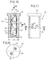
- Fig. 10 shows the contact in the position of Fig. 7 as a component a halogen lamp holder 25, the insulating body with 26 is designated.
- the insulating body 26 is divided into a shaft 27 and in contrast, a widened head 28.
- the diameter of the head 28th is only about 10 mm and the shaft diameter 29 accordingly the wall thickness of the trimmed tube is significantly smaller.
- each contact pin is from the bend 21st of the upper contact spring end with reference to FIG. 10 and kept electrically contacting.
- connection conductors become a lower one in axial alignment from below Opening 33 is inserted into the further contact zone designated 32.
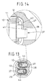
- the contact according to the invention has another special feature on, which is that in the U-web 14 of the contact body 11 a stop tab 43 is released and into the interior 22 of the Contact 10 is molded into it.
- This stop tab 43 serves as Insertion limit for the one to be inserted from below with regard to the figures electrical conductor and / or for the to be inserted from above Lamp pin.
- the special feature of the stop plate 43 is that they start from the conductor and / or lamp contact pin its narrow edge is contacted. Forces acting on them are thus exercised in the direction of the bending line 44 around which the Stop tab 43 was deformed. As a result, the stop tab 43 particularly stable or can, in order to perform its function safely, be quite thin. 13 shows the stop tabs 44 with a view on their narrow abutment surfaces or edges.
- FIG. 15 While previously the contact 10 individually or in combination with a halogen lamp holder 25 is shown in FIG. 15 another embodiment. There is a contact 10 as Connection or connecting terminal 46 designed for two conductors, which is why both ends 19 and 20 of the contact spring 12 conductor clamping edges 23 have at their free ends.
- the contact 10 is of a tubular insulating sheath 45 surrounded, preferably formed as a hose is.
- the insulating jacket is used to ensure electrical safety clearly above the two ends of the contact 10 in front.
Landscapes
- Connecting Device With Holders (AREA)
Abstract
Description
Die Erfindung bezieht sich zunächst auf einen elektrischen Kontakt,
insbesondere für Lampenfassungen, Anschluss- oder Verteilerklemmen
od. dgl., zum Anschluss elektrischer Leiter wie Drähte oder
Kontaktstifte, mit einem Kontaktkörper und einer Kontaktfeder, die aus
je einem gesonderten Metallstreifen geformt sind, wobei der Kontaktkörper
eine Art Rahmenbauteil ausbildet, an dem die Kontaktfeder
gehalten ist, und wobei zwischen wenigstens einer Innenfläche des
Kontaktkörpers und Kontaktabschnitten der Kontaktfeder Kontaktzonen
ausgebildet sind, nach dem Oberbegriff des Anspruchs 1.The invention first relates to an electrical contact,
especially for lamp holders, connection or distribution terminals
or the like. For connecting electrical conductors such as wires or
Contact pins, with a contact body and a contact spring, made of
are each formed a separate metal strip, the contact body
forms a kind of frame component on which the contact spring
is held, and wherein between at least one inner surface of the
Contact body and contact sections of the contact spring contact zones
are formed according to the preamble of
DE 93 09 139 U1 zeigt und beschreibt eine Lampenfassung für Halogenlampen mit einem aus Isolierstoff bestehenden Kontaktträger und zwei sog. Klemmkontakten. Jeder Klemmkontakt, der die Aufgabe hat, die elektrische Verbindung zwischen einem Anschlussleiter und einem Lampenkontaktstift herzustellen, ist hier zweiteilig ausgebildet. Der eine Teil ist kastenartig gestaltet und wird in den Isolierkörper eingepresst, wo er sich mit Hilfe einer widerhakenartig wirkenden Rastnase gegen Herausfallen verkrallt. Der in den Hohlraum des kastenförmigen ersten Teiles eingelegte zweite Teil besteht aus einer im wesentlichen S-förmig gebogenen Blattfeder. Diese weist ein sich im wesentlichen gerade erstreckendes Ende mit einer frontseitigen Klemmkante und ein anderes umgebogenes Ende auf. Das Ende mit der Klemmkante bildet mit der benachbarten Wand des kastenförmigen Teiles eine schraubenlose Anschlussklemme für das abisolierte Ende eines einzusteckenden elektrischen Leiters aus. Das andere, rund gebogene Ende dient dazu, den Lampenkontaktstift zwischen sich und der dort benachbarten Innenwand des kastenförmigen Körpers durch Kraftschluss zu kontaktieren.DE 93 09 139 U1 shows and describes a lamp holder for Halogen lamps with a contact carrier made of insulating material and two so-called clamping contacts. Every terminal contact that does the job has the electrical connection between a connecting conductor and To manufacture a lamp contact pin is formed here in two parts. One part is box-shaped and is pressed into the insulating body, where he sits with the help of a barbed latch clawed against falling out. The one in the cavity of the box-shaped The first part inserted second part consists of a essentially S-shaped leaf spring. This shows itself in essentially straight extending end with a front Clamping edge and another bent end. The end with the clamping edge forms with the adjacent wall of the box-shaped Part of a screwless terminal for the stripped End of an electrical conductor to be inserted. The other, Round curved end serves to place the lamp contact pin between himself and the adjacent inner wall of the box-shaped body to contact by adhesion.
Grundsätzlich ist die Ausgestaltung von Kontakten aus zwei Teilen insofern von Vorteil, als Teile verschiedener Materialien verwendet werden können. So ist es insbesondere empfehlenswert, die Kontaktfeder z.B. aus einem Chrom-Nickel-Streifen zu formen, der hervorragende Federeigenschaften selbst bei hohen Temperaturen aufweist. Der andere Teil des Kontaktes kann z.B. ein Kupferteil sein, welches sich durch optimale elektrische Leitfähigkeit und hohe mechanische Stabilität auszeichnet. Unter diesen Aspekten ist die zweiteilige Anschlussklemme, wie sie Gegenstand von DE 93 09 139 U1 ist, vorteilhaft. Wie aus den Zeichnungen dieses Dokuments ersichtlich ist, benötigen die Anschlussklemmen jedoch einen beträchtlichen Raumbedarf. Sie eignen sich daher z.B. nicht zum Einbau in Halogenlampenfassungen geringeren Durchmessers, wie sie beispielsweise für den Einsatz in so genannte Posamentrohre mit einem Außendurchmesser von etwa 10 mm und einem Innendurchmesser von nur ca. 8 mm benötigt werden.Basically, the design of contacts consists of two parts to the extent that parts of different materials are used can be. So it is particularly recommended to use the contact spring e.g. to form from a chrome-nickel strip, the excellent Has spring properties even at high temperatures. The other part of the contact can e.g. be a copper part, which is characterized by optimal electrical conductivity and high mechanical Stability distinguishes. Under these aspects is the two-part Terminal as it is the subject of DE 93 09 139 U1 advantageous. As can be seen from the drawings in this document, however, the terminals require a considerable amount of space. They are therefore suitable e.g. not for installation in halogen lamp sockets smaller diameter, such as for use in so-called trimmings with a Outside diameter of about 10 mm and an inside diameter of only approx. 8 mm are required.
Eine derartige Halogenlampenfassung ist in DE 195 10 623 C2 dargestellt und beschrieben. Um hier die erforderlichen geringen. Einbaumaße der Kontakte zu gewährleisten, sind diese relativ flach ausgebildet und an die abisolierten Enden der Leiter angecrimpt. Auf diese Weise lassen sich zwei relativ kleine Kontakte im selben Querschnittbereich des Fassungskörpers unterbringen.Such a halogen lamp holder is in DE 195 10 623 C2 shown and described. To make the necessary minor here. Mounting dimensions To ensure the contacts, they are relatively flat and crimped onto the stripped ends of the conductors. On in this way two relatively small contacts can be made in the same cross-sectional area of the socket body.
Von diesem Stand der Technik ausgehend, ist es eine Aufgabe der vorliegenden Erfindung, einen elektrischen Kontakt anzugeben, der die Vorteile der beiden bekannten Kontakte in sich vereinigt. Das bedeutet, der der Erfindung zugrundeliegende Kontakt sol! einerseits aus zwei Teilen unterschiedlicher Materialien bestehen können, jedoch, insbesondere im Querschnittsprofil, sehr klein bauen und eine hohe Stabilität aufweisen.Based on this state of the art, it is a task of the present invention to provide an electrical contact which combines the advantages of the two known contacts. The means the contact on which the invention is based sol! on the one hand can consist of two parts of different materials, however, especially in the cross-sectional profile, build very small and one have high stability.
Die Erfindung löst diese Aufgabe mit den Merkmalen des
Anspruchs 1 und ist dem entsprechend dadurch gekennzeichnet, dass
der Kontaktkörper im Querschnitt im wesentlichen U-förmig ausgebildet
ist, dass die Kontaktfeder einen Basisabschnitt aufweist, der die U-Form
des Kontaktkörpers zu einem Röhrchen ergänzt und die Kontaktabschnitte
der Kontaktfeder an den Schmalenden des langgestreckten
Basisabschnitts angeformt sind und sich von der selben
Flachseite des Basisabschnitt aus weg erstrecken, derart, dass die
beiden Kontaktzonen in Längsrichtung des Kontakts hintereinander
angeordnet sind.The invention solves this problem with the features of
Der wesentliche Kern der Erfindung besteht demnach in der Ausgestaltung des Kontakts als Röhrchenkontakt geringen Querschnittsprofils. Im Unterschied zu dem in DE 93 09 130 U1 beschriebenen Kontakt ist hier die Kontaktfeder in nicht einem käfigartigen Kontaktkörper untergebracht, sondern ergänzt den zunächst im wesentlichen lediglich U-förmigen Kontaktkörper zu dem Röhrchenkontakt. Folglich ist die Kontaktfeder nicht in den Kontaktkörper hineingebaut, sondern quasi Teil seines Umfangs. Diese eigenwillige Konstruktion ermöglicht es, den Kontakt, der durchaus langgestreckt sein kann, im Querschnitt äußerst klein zu halten. Somit eignen sich Kontakte der erfindungsgemäßen Art zum Einbau in Isolierstoff-Fassungskörper geringen Durchmessers, insbesondere also für Halogenlampenfassungen, die zum Einsatz in Posamentrohre o.ä. von 10 mm Durchmesser geeignet sind.The essential essence of the invention is therefore in Design of the contact as a tube contact with a small cross-sectional profile. In contrast to that described in DE 93 09 130 U1 Contact here is the contact spring in not a cage-like one Contact body housed, but initially complements the essentially only U-shaped contact body to the tube contact. Consequently, the contact spring is not built into the contact body, but part of its scope. This idiosyncratic Construction allows the contact to be elongated can be extremely small in cross section. Thus are suitable Contacts of the type according to the invention for installation in insulating material socket bodies small diameter, especially for halogen lamp holders, for use in trimmed tubes or similar of 10 mm Diameters are suitable.
Im Durchmesser kleine, langgestreckte Kontakte sind grundsätzlich bekannt, wozu beispielsweise auf US 4 084 876 A verweisen wird. In diesem Dokument ist ein Leitungsverbinder dargestellt und beschrieben mit einem Kontakt, der in Axialrichtung hintereinander zwei schraubenlose Anschlussklemmen für abisolierte Leiterenden aufweist und dessen Isolierkörper aus einem röhrchenförmigen Spritzgießteil besteht, in welches der Kontakt eingeschoben ist.Long, small-diameter contacts are essential is known, for which reference, for example, to US Pat. No. 4,084,876 becomes. In this document, a line connector is shown and described with a contact in the axial direction one behind the other two screwless terminals for stripped wire ends has and the insulating body from a tubular injection molded part exists in which the contact is inserted.
Zwar hat auch dieser Kontakt angenähert die Form eines im Querschnitt kleinen Röhrchens, doch bleibt über die gesamte Länge des Kontaktes ein Längsschlitz offen, wodurch die Stabilität des Kontaktes gering ist. Außerdem besteht der gesamte Kontakt, also sein den Kontaktkörper darstellender Abschnitt wie auch sein die Kontaktfedern ausbildender Abschnitt aus einem einstückigen Bauteil und folglich auch nur aus einem einzigen Material, also entweder z.B. Kupfer oder z.B. Chrom-Nickel-Stahl. Mit einem derartigen Kontakt lassen sich die Ziele die Erfindung demnach nicht erreichen.This contact also approximated the shape of an im Cross-section of small tube, but remains over the entire length of the contact a longitudinal slot open, which increases the stability of the contact is low. In addition, there is all contact, so be the portion representing the contact body as well as the Section forming contact springs from a one-piece component and consequently only from a single material, i.e. either e.g. Copper or e.g. Chromium-nickel steel. With such a contact the objectives of the invention cannot therefore be achieved.
In einer Ausgestaltung der Erfindung ist der langgestreckte Basisabschnitt der Kontaktfeder als im wesentlichen ebener Streifen ausgebildet, dessen Enden schräg gegen die Innenseite des zentralen Steges des U-förmigen Kontaktkörpers weisend umgebogen sind. Durch diese konstruktive Lösung kann der zentrale Steg des U-förmigen Kontaktkörpers praktisch ebenso lang sein wie der Kontaktkörper, und die gesamte Kontaktfeder lässt sich aus einem schmalen länglichen Blechstreifen durch Ausschneiden und Biegen erzeugen.In one embodiment of the invention, the elongated Base portion of the contact spring as a substantially flat strip formed, the ends of which slant towards the inside of the central Web of the U-shaped contact body are bent pointing. This constructive solution allows the central web of the U-shaped Contact body be practically as long as the contact body, and the entire contact spring can be made from a narrow elongated Create sheet metal strips by cutting and bending.
Eine weitere Ausführung entsprechend der Erfindung sieht vor, dass den U-Schenkeln des Kontaktkörpers Befestigungslaschen angeformt sind zur Verbindung der Kontaktfeder mit dem Kontaktkörper, wobei die die Befestigungslaschen durch Umgreifen von Randpartien des Basisabschnitts der Kontaktfeder diese am Kontaktkörper festlegen können. Durch einfaches Umbiegen der Befestigungslaschen wird die streifenförmige Kontaktfeder mit den U-Schenkeln des Kontaktkörpers zu einem insgesamt sehr stabilen und kompakten Kontaktelement fest verbunden.Another embodiment according to the invention provides that the U-legs of the contact body mounting tabs are molded to connect the contact spring to the contact body, wherein the the fastening tabs by reaching around the edge of the base portion of the contact spring on the contact body can set. By simply bending the fastening tabs the strip-shaped contact spring with the U-legs of the Contact body to an overall very stable and compact Contact element firmly connected.
Im Sinne der gewünschten Miniaturisierung des Kontaktes ist ein weiteres Merkmal von Vorteil, welches darin besteht, dass der Basisabschnitt der Kontaktfeder mit Randausklinkungen versehen ist, in die die Befestigungslaschen des Kontaktkörpers eintauchen. Damit ist eine Anordnung geschaffen, die sich dadurch auszeichnet, dass die Breite des Basisabschnitts der Kontaktfeder außerhalb der Anordnungsbereiche der Randausklinkungen gleich oder nur geringfügig größer ist als der Außenabstand der U-Schenkel des Kontaktkörpers voneinander. Die Randausklinkungen ermöglichen also in gewisser Weise eine "Formintegration" der Kontaktfeder in den Kontaktkörper.In terms of the desired miniaturization of the contact Another feature of advantage, which is that the Base section of the contact spring is provided with edge notches, into which the fastening tabs of the contact body are inserted. In order to an arrangement is created which is characterized in that the Width of the base portion of the contact spring outside the arrangement areas the edge notches equal or only slightly is larger than the outer distance of the U-legs of the contact body from each other. The edge notches thus allow to a certain extent Way a "shape integration" of the contact spring in the contact body.
Im Hinblick auf die von der Erfindung angestrebte besondere Stabilität des miniaturisierten Kontakts ist ein Merkmal von Vorteil, welches darin besteht, dass die Kontaktzonen in jeweils den gleichen Querschnittsbereichen des Kontakts angeordnet sind wie die Befestigungslaschen. Die im Betrieb höchstmögliche Belastung in den Kontaktzonen übt also genau dort Reaktionskräfte aus, wo die Kontaktfeder am Kontaktkörper festgelegt ist. Diejenigen Zonen und Bereiche, die keine unmittelbare Verbindung miteinander haben, werden nicht kräftemäßig beansprucht und können daher z.B. auch nicht ausbeulen oder in irgendeiner anderen Art sich verformen.With regard to the particular desired by the invention Stability of the miniaturized contact is a feature advantageous which consists of the contact zones being in the same Cross-sectional areas of the contact are arranged like the fastening tabs. The highest possible load in the contact zones during operation exerts reaction forces exactly where the contact spring is fixed on the contact body. Those zones and areas who have no direct connection with each other will not strained and can therefore e.g. also do not bulge or deform in any other way.
Zur Einsteckbegrenzung für einen Leiter und/oder den Kontaktstift einer Lampe ist die Anordnung bevorzugt des weiteren so getroffen, dass in einem Bereich zwischen den Kontaktzonen aus dem Kontaktkörper eine Anschlaglasche ausgeklinkt und derart in den Kontaktkörper hinein verformt ist, dass sie mit wenigstens einer ihrer schmalen Kanten eine Einsteckbegrenzung ausbildet. Ausgeklinkte und umgebogene Einsteckbegrenzungen sind beispielsweise auch in US 4 084 876 A offenbart. Dort trifft allerdings der jeweilige Leiter lotrecht auf die hochgestellte breite Fläche des Abschnitts und ist somit quer zu dessen Umbiegeachse gerichtet, wohingegen die Besonderheit des erfindungsgemäßen Merkmales darin besteht, dass nicht die breite Fläche, sondern die schmale Kante der umgebogenen Anschlaglasche die Einsteckbegrenzung ausbildet. Das Material selbst braucht daher die entstehenden Kräfte nicht aufzunehmen und kann deshalb auch dünn sein.For insertion limitation for a conductor and / or the contact pin the arrangement of a lamp is preferably further made such that in an area between the contact zones from the Contact body released a stop tab and so in the Contact body is deformed into that with at least one of their narrow edges forms an insertion limit. notched and bent insertion limits are also in, for example US 4 084 876 A discloses. There, however, the respective leader meets vertically on the superscript wide area of the section and is thus directed transversely to its bending axis, whereas the peculiarity of the feature of the invention is that not wide area, but the narrow edge of the bent Stop tab forms the insertion limit. The material itself therefore does not need to absorb the resulting forces and can therefore be thin.
Gemäß einer weiteren Ausgestaltung ist vorgesehen, dass die freien Enden der Kontaktabschnitte der Kontaktfeder im wesentlichen gerade gegen die Innenseite des zentralen Steges des U-förmigen Kontaktkörpers weisend verlaufen und jeweils eine Klemmkante für einen Leiter ausbilden. Ein derartiger Kontakt käme insbesondere als oder in einer Anschluss- oder Verbindungsklemme in Betracht, wie sie vom Prinzip her in US 4 084 876 A beschrieben ist und die dazu dient, zwei im wesentlichen axial einander gegenüberliegende Leiterenden aufzunehmen.According to a further embodiment it is provided that the free ends of the contact sections of the contact spring essentially straight against the inside of the central web of the U-shaped Contact body pointing and each have a clamping edge for train a leader. Such contact would come in particular as or in a connection or connection terminal, as they are considered is described in principle in US 4,084,876 A and is used to two substantially axially opposite conductor ends take.
Bei einer anderen Ausführung ist vorgesehen, dass das Ende des einen Kontaktabschnitts der Kontaktfeder im wesentlichen gerade gegen die Innenseite des zentralen Steges des U-förmigen Kontaktkörpers weisend verläuft und eine Klemmkante für einen Leiter ausbildet, während der andere Kontaktabschnitt der Kontaktfeder von einer Umbiegung ausgebildet ist, die einen zunächst gegen die Innenseite des zentralen Steges des U-förmigen Kontaktkörpers weisend verlaufenden Abschnitt von dem zentralen Steg wegführt und eine Druckkontaktzone für einen Kontaktstift wie Lampenkontaktstift ausbildet. Der Kontaktstift ist dann mit einer definierten Kraft aus dem Kontakt wieder herausziehbar, wird also nicht festgeklemmt. Dieser Kontakt eignet sich hervorragend zum Einbau z.B. in eine Halogenlampenfassung.Another embodiment provides that the end of the one contact section of the contact spring essentially straight against the inside of the central web of the U-shaped contact body runs in a pointing manner and forms a clamping edge for a conductor, while the other contact portion of the contact spring from one Bend is formed, one against the inside of the central web of the U-shaped contact body pointing Section leads away from the central web and a pressure contact zone for a contact pin such as lamp contact pin. The contact pin is then out of contact with a defined force can be pulled out again, so it is not clamped. That contact is ideal for installation e.g. in a halogen lamp holder.
Schließlich betrifft die Erfindung eine Lampenfassung, insbesondere eine Halogenlampenfassung, umfassend einen Fassungskörper aus Isolierstoff mit einem länglichen Schaft und einem mit Durchstecköffnungen für Kontaktstifte versehenen plattenartigen Kopf sowie mit Kanälen zur Aufnahme von Kontakten zum Anschluss von Leiterenden für die Spannungsversorgung der Kontaktstifte, wobei die Fassung gekennzeichnet ist durch Kontakte entsprechend der Erfindung.Finally, the invention relates to a lamp holder, in particular a halogen lamp socket comprising a socket body Made of insulating material with an elongated shaft and one with push-through openings for contact pins provided plate-like head and with channels for receiving contacts for connecting conductor ends for the power supply of the contact pins, the socket is characterized by contacts according to the invention.
Bei einer solchen Fassung ist es des weiteren im Zusammenhang mit einem Kontakt, der zur Steckverankerung in ein im Isolierkörper aus dem Basisabschnitt der Kontaktfeder eine widerhakenartig wirkende Rastzunge ausgeschnitten und nach außen ausgeformt ist, von Bedeutung, wenn die Rastzunge eine Ausklinkung aufweist, die die Rastzunge in eine breitere Basis und eine schmalere Endzunge unterteilt, so dass die vordere Kante der breiteren Basis einen Anschlag zur Abstützung an der Laibung eines Fensters im Isolierkörper der Fassung ausbildet, in welches nur die schmalere Endzunge eingreifen kann. Auf diese Weise erfolgt eine besondere Art der Steck-Verriegelung des Kontakts im Isolierkörper, der gewährleistet, dass z.B. durch Zug am eingesteckten Leiter diese Rastzunge sich nicht verformen kann und folglich auch - selbst unter erhöhten Auszugkräften - der Kontakt nicht aus dem Isolierstoffkörper austreten kann. Dies verhindert einen Masseschluss zum den Isolierstoffkörper umgebenden Posamentrohr.In such a version, it is also related with a contact that is used for anchoring in an insulator a barb-like from the base portion of the contact spring acting latch is cut out and shaped outwards, important if the locking tongue has a notch that the latch tab into a wider base and a narrower end tab divided so that the leading edge of the wider base one Stop for support on the reveal of a window in the Insulating body of the socket forms, in which only the narrower Can engage end tongue. This is a special way the plug lock of the contact in the insulator, the ensures that e.g. by pulling on the inserted conductor Locking tongue cannot deform and consequently also - even under increased pull-out forces - the contact does not come out of the insulating body can leak. This prevents a short to ground Isolation body surrounding trimmed tube.
Sodann und schließlich bezieht sich die Erfindung auch auf eine Anschluss- oder Verbindungsklemme unter Verwendung eines Kontaktes mit erfindungsgemäßen Merkmalen, wobei der Kontakt von einer schlauchförmigen Isolierumhüllung umgeben ist, die bevorzugt von einem Schrumpfschlauch ausgebildet ist.Then and finally, the invention also relates to a Terminal block using a contact with features according to the invention, the contact of is surrounded by a tubular insulating sheath, which is preferred is formed by a shrink tube.
Im übrigen versteht sich die Erfindung am besten anhand der nachfolgenden Beschreibung mehrerer in den Zeichnungen dargestellter Ausführungsbeispiele. In den Zeichnungen zeigen:
- Fig. 1
- den Kontaktkörper eines Kontakts in schaubildlicher Ansicht,
- Fig. 2
- den aus einem streifenförmigen Blech ausgeschnittenen Zuschnitt für den Kontaktkörper vor seiner Verformung in die Konfiguration nach Fig. 1,
- Fig. 3
- eine schaubildliche Darstellung der zugehörigen Kontaktfeder,
- Fig. 4
- der aus einem Blechstreifen ausgeschnittene Zuschnitt für die Kontaktfeder vor seiner Verformung in die Konfiguration nach Fig. 3,
- Fig. 5
- eine perspektivische Ansicht des fertig montierten, aus Kontaktkörper und Kontaktfeder bestehenden Kontakts,
- Fig. 6
- eine Stirnansicht des Kontakts nach Fig. 5 mit Blick auf die Außenseite der Kontaktfeder,
- Fig. 7
- einen Längsschnitt durch den Kontakt entsprechend der Schnittlinie VII-VII in Fig. 6,
- Fig. 8.
- eine Ansicht auf die Rückseite des Kontaktkörpers des Kontakts,
- Fig. 9
- eine Stirnansicht des Kontakts in Richtung des Ansichtspfeils IX in Fig. 7,
- Fig. 10
- einen Längsschnitt durch eine Halogenlampenfassung und einen in ihr befindlichen Kontakt,
- Fig. 11
- eine Außenansicht der Lampenfassung nach Fig. 10 entsprechend dem dortigen Ansichtspfeil XI,
- Fig. 12
- eine Aufsicht auf die Lampenfassung nach dem Ansichtspfeil XII in Fig. 10,
- Fig. 13
- einen Querschnitt durch die Lampenfassung nach Fig. 10 bzw. 11 entsprechend der Schnittangabe XIII-XIII in Fig. 11,
- Fig. 14
- eine erheblich vergrößerte Detaildarstellung einer Einzelheit aus Fig. 13,
- Fig. 15
- einen Längsschnitt durch eine Anschluss- oder Verbindungsklemme mit einem Kontakt zur Verbindung zweier Leiter.
- Fig. 1
- the contact body of a contact in a diagrammatic view,
- Fig. 2
- the blank cut from a strip-shaped sheet for the contact body before it is deformed into the configuration according to FIG. 1,
- Fig. 3
- a graphical representation of the associated contact spring,
- Fig. 4
- the blank cut out from a sheet metal strip for the contact spring before it is deformed into the configuration according to FIG. 3,
- Fig. 5
- 2 shows a perspective view of the fully assembled contact consisting of contact body and contact spring,
- Fig. 6
- 5 with a view of the outside of the contact spring,
- Fig. 7
- 6 shows a longitudinal section through the contact according to section line VII-VII in FIG. 6,
- Fig. 8.
- a view of the back of the contact body of the contact,
- Fig. 9
- 7 shows an end view of the contact in the direction of the arrow IX in FIG. 7,
- Fig. 10
- a longitudinal section through a halogen lamp socket and a contact located therein,
- Fig. 11
- 10 according to the view arrow XI there,
- Fig. 12
- a view of the lamp holder according to the arrow XII in Fig. 10,
- Fig. 13
- 10 and 11 corresponding to the section XIII-XIII in Fig. 11,
- Fig. 14
- 13 shows a considerably enlarged detailed illustration of a detail from FIG. 13,
- Fig. 15
- a longitudinal section through a connection or connecting terminal with a contact for connecting two conductors.
Ein in seiner Gesamtheit mit 10 bezeichneter Kontakt ist zweiteilig
ausgebildet. Er umfasst einen Kontaktkörper 11 und eine Kontaktfeder
12.A contact designated 10 in its entirety is in two parts
educated. It comprises a
Der Kontaktkörper 11 ist aus einem ebenen Blechzuschnitt 13
z.B. aus Kupfer im wesentlichen U-artig geformt, so dass er drei definierte
Abschnitte, nämlich einen U-Steg 14 und zwei zueinander
parallel verlaufende U-Schenkel 15 aufweist. Beim dargestellten Ausführüngsbeispiel
ist der U-Steg 14 nicht eben, sondern wie z.B. aus
Fig. 1 ersichtlich, leicht nach außen gewölbt. Über die freien Enden der
U-Schenkel 15 ragen jeweils paarweise an zwei in Axialrichtung voneinander
beabstandeten Bereichen Befestigungslaschen 16 vor, deren
Funktion weiter unten erläutert wird.The
Die Kontaktfeder 12 ist aus einem Zuschnitt 17 aus insbesondere
Chrom-Nickel-Stahlblech geformt. Sie unterteilt sich in einen im
Querschnitt flachrechteckigen und ansonsten langgestreckten Basisabschnitt
18, dessen beide Enden umgebogen sind. Der Endabschnitt
des in Fig. 3 unteren Endes 19 verläuft im wesentlichen geradlinig,
während das dort obere Ende 20 noch eine Umbiegung 22 aufweist.
Hierauf wird später eingegangen.The
Die Fig. 1 und 3 zeigen Kontaktkörper 11 und Kontaktfeder 12
zwar voneinander beanstandet, jedoch in lagegerechter Zuordnung.
Somit ist ersichtlich, dass der gerade Endabschnitt 19 wie auch der
Endabschnitt 20 bzw. dessen Umbiegung 21 bei zusammengesetzten
Teilen gegen die Innenseite des U-Steges 14 des Kontaktkörpers 11
weisen.1 and 3
Wie aus den Fig. 3 und 4 ersichtlich ist, weist der Basisabschnitt
18 der Kontaktfeder 12 Randausklinkungen 22 auf, die nach Anordnung
und Lage den Befestigungslaschen 16 des Kontaktkörpers 11
zugeordnet sind. Die Fig. 5 und 6 veranschaulichen deutlich deren
Zusammenspiel, nämlich das randliche Eingreifen der Befestigungslaschen
16 in die Randausklinkungen 22 und das Umgreifen der
umgebogenen Befestigungslaschen 16 hinter den Rücken des
Basisabschnitts 18 der Kontaktfeder 12. Wie die Fig. 5 und 6 zeigen,
wird durch dieses Zusammenfügen von Kontaktkörper 11 und
Kontaktfeder 12 insgesamt ein rundum geschlossener Kontakt 10
geschaffen, den man als Röhrchenkontakt bezeichnen kann.As can be seen from FIGS. 3 and 4, the
Wie der Längsschnitt nach Fig. 7 zeigt, verläuft der untere, im
wesentlichen gerade Abschnitt 19 der Kontaktfeder 12 schräg gegen
die rückwärtige Innenseite 14a des Kontaktkörpers 11 und bildet
zusammen mit diesem eine schraubenlose Anschlussklemme für
bezüglich Fig. 7 von unten einzusteckende abisolierter Leiterenden
aus. Wird ein Leiterende eingesteckt, so wird der gerade Abschnitt
weiter nach oben und von der Innenfläche 14a weg geführt, bis das
abisolierte Ende durch den Spalt zwischen der Klemmkante 23 und
der inneren Rückfläche 14a hindurchtreten kann und die Klemmkante
23 den Leiter entgegen im Lösesinne wirkender Rückzugskräfte festhält.
Die hier bestehende Kontaktzone 31 liegt etwa in Höhe der beiden
unteren Befestigungslaschen 16.As the longitudinal section according to FIG. 7 shows, the lower one runs in
essential
Im Bereich der oberen Befestigungslaschen 16 liegt die zusammen
mit der Umbiegung 21 definierte Kontaktzone 32 für einen bezüglich
Fig. 7 von oben einzusteckenden Lampenkontaktstift. Ausgehend
von der Basis 18 der Kontaktfeder 12 erstreckt sich zunächst ein
Abschnitt 20 schräg gegen die innere Rückenfläche 14a des Kontaktkörpers
11 und nach der Umbiegung 21 strebt ein freier Endabschnitt
24 wieder von dieser Fläche 14 weg.In the area of the
Fig. 10 zeigt den Kontakt in der Position der Fig. 7 als Bestandteil
einer Halogenlampenfassung 25, deren Isolierkörper mit 26
bezeichnet ist. Der Isolierkörper 26 gliedert sich in einen Schaft 27 und
einen demgegenüber verbreiterten Kopf 28. Im Rahmen der Erfindung
ist bei solchen Lampenfassungen insbesondere an solche gedacht, die
man mit dem Schaft 27 in die Höhlung eines sogenannten Posamentrohres
einsetzen kann, wobei der Durchmesser des Kopfes 28
nur etwa 10 mm beträgt und der Schaftdurchmesser 29 entsprechend
der Wandstärke des Posamentrohres noch deutlich kleiner ist.Fig. 10 shows the contact in the position of Fig. 7 as a component
a
Bestimmungsgemäß befinden sich auf der Stirnseite der Kopfplatte
28 zwei Einstecköffnungen 30 für nicht dargestellte Kontaktstifte
einer Halogenlampe. Jeder Kontaktstift wird von der Umbiegung 21
des bezüglich Fig. 10 oberen Kontaktfederendes andrückend und
elektrisch kontaktierend gehalten.As intended, they are located on the front of the
Die abisolierten Enden von ebenfalls nicht dargestellten
Anschlussleitern werden etwa in axialer Flucht von unten eine untere
Öffnung 33in die mit 32 bezeichnete weitere Kontaktzone eingeführt.The stripped ends of also not shown
Connection conductors become a lower one in axial alignment from below
Wie aus Fig. 10 nicht ersichtlich ist, wird bei der Montage der
Fassung 25 der Kontakt 10 durch die untere Öffnung 33 in den Isolierkörper
26 eingesteckt, bis das obere Stirnende 34 des Kontaktes 10
an der Unterfläche 35 des Kopfteils 28 des Fassungskörpers 27
anschlägt.As is not apparent from FIG. 10, the
In der der Kontaktfeder 12 zugewandten Seitenwand des Isolierkörpers
27 befindet sich ein Fenster 36 zur teilweisen Aufnahme
einer Verriegelungszunge 37, die Bestandteil der Kontaktfeder 12 ist.In the side wall of the insulating body facing the
Wie insbesondere die Fig. 3, 5, 7 und 10 zeigen, ist die Verriegelungszunge
37 aus dem zentralen Basisabschnitt 18 der Kontaktfeder
12 ausgeschnitten und nach außen ausgebogen. Im übrigen
weist die Verriegelungszunge 37 die Besonderheit auf, dass sie in
Folge einer seitlichen Randausklinkung 38 in eine breitete Basis 39
und eine schmalere Endzunge 40 unterteilt ist. Damit wird erreicht,
dass nur die schmalere Endzunge 40 in das Fenster 36 eintreten kann,
wohingegen (Fig. 10) die zum freien Ende hinweisende Kante 41
gegen die Laibung 42 des Fensters 36 stößt. Daraus resultiert der
Vorteil, dass die Halterung des Kontaktes 10 im Isolierkörper 26 selbst
unter Einwirkung von Auszugkräften, die bezüglich Fig. 10 nach unten
hin durch Zug am elektrischen Leiter ausgeführt werden, sehr sicher
ist. Die Verriegelungszunge 37 kann aufgrund ihres formschlüssigen
Rückhalts durch die "Ausstellbegrenzung" nicht so verformt werden,
dass sich der Kontakt 10 aus dem Isolierkörper 27 herausziehen ließe.3, 5, 7 and 10 show in particular, the locking
Im übrigen zeigt Fig. 14 die Ausstellbegrenzung für die Verriegelungszunge
37 im Schnitt und in stark vergrößerter Darstellung
besonders deutlich.14 shows the opening limit for the locking
Der erfindungsgemäße Kontakt weist noch eine weitere Besonderheit
auf, die darin besteht, dass im U-Steg 14 des Kontaktkörpers
11 eine Anschlaglasche 43 ausgeklinkt und in den Innenraum 22 des
Kontaktes 10 hinein geformt ist. Diese Anschlaglasche 43 dient als
Einsteckbegrenzung für den bezüglich der Figuren von unten her einzusteckenden
elektrischen Leiter und/oder für den von oben einzusteckenden
Lampenkontaktstift. Die Besonderheit der Anschlaglasche 43
besteht darin, dass sie vom Leiter und/oder Lampenkontaktstift an
ihrer schmalen Randkante kontaktiert wird. Auf sie einwirkende Kräfte
werden also in Richtung der Biegelinie 44 ausgeübt, um die die
Anschlaglasche 43 verformt wurde. Infolgedessen ist die Anschlaglasche
43 besonders stabil bzw. kann, um ihre Funktion sicher auszuüben,
recht dünn sein. Fig. 13 zeigt die Anschlaglaschen 44 mit Blick
auf ihre schmalen Anschlagflächen bzw. -kanten.The contact according to the invention has another special feature
on, which is that in the
Während bisher der Kontakt 10 einzeln oder im Zusammenhang
mit einer Halogenlampenfassung 25 beschrieben wurde, zeigt Fig. 15
ein weiteres Ausführungsbeispiel. Dort ist ein Kontakt 10 als
Anschluss- oder Verbindungsklemme 46 für zwei Leiter gestaltet, weshalb
beide Enden 19 und 20 der Kontaktfeder 12 Leiter-Klemmkanten
23 an ihren freien Enden aufweisen.While previously the
Im übrigen ist der Kontakt 10 von einer schlauchförmigen Isolierumhüllung
45 umgeben, die bevorzugt als Strumpfschlauch ausgebildet
ist. Zur Gewährleistung der elektrischen Sicherheit steht die Isolierumhüllung
deutlich über die beiden Stirnenden des Kontaktes 10
vor.For the rest, the
Claims (17)
Applications Claiming Priority (2)
| Application Number | Priority Date | Filing Date | Title |
|---|---|---|---|
| DE10117570 | 2001-04-07 | ||
| DE10117570A DE10117570B4 (en) | 2001-04-07 | 2001-04-07 | Electrical contact and lamp socket and connection or connection terminal with at least one such contact |
Publications (3)
| Publication Number | Publication Date |
|---|---|
| EP1248318A2 true EP1248318A2 (en) | 2002-10-09 |
| EP1248318A3 EP1248318A3 (en) | 2003-11-19 |
| EP1248318B1 EP1248318B1 (en) | 2010-05-19 |
Family
ID=7680888
Family Applications (1)
| Application Number | Title | Priority Date | Filing Date |
|---|---|---|---|
| EP02004723A Expired - Lifetime EP1248318B1 (en) | 2001-04-07 | 2002-03-01 | Electrical contact as well as lamphoder and connecting terminal with at least such a contact |
Country Status (4)
| Country | Link |
|---|---|
| EP (1) | EP1248318B1 (en) |
| AT (1) | ATE468630T1 (en) |
| DE (1) | DE10117570B4 (en) |
| ES (1) | ES2344732T3 (en) |
Cited By (6)
| Publication number | Priority date | Publication date | Assignee | Title |
|---|---|---|---|---|
| US7040852B2 (en) | 2002-04-25 | 2006-05-09 | Teijin Seiki Co., Ltd. | Robot arm mechanism and robot apparatus |
| GB2423422A (en) * | 2004-02-21 | 2006-08-23 | Hitesh Dhanji Patel | Electrical connector preventing withdrawal of conductor |
| DE102007016070A1 (en) * | 2007-04-03 | 2008-10-09 | Lear Corp., Southfield | Electrical connection arrangement and method for using the electrical connection arrangement |
| EP2149933A1 (en) * | 2008-07-30 | 2010-02-03 | Lights CO. S.r.l. | Lamp socket with fast connection terminals |
| WO2012083320A1 (en) * | 2010-12-21 | 2012-06-28 | Tridonic Connection Technology Gmbh & Co Kg | Connection terminal or connecting terminal for electrical conductors |
| WO2014111346A1 (en) * | 2013-01-17 | 2014-07-24 | Phoenix Contact Gmbh & Co. Kg | Terminal clamp |
Citations (3)
| Publication number | Priority date | Publication date | Assignee | Title |
|---|---|---|---|---|
| US4084876A (en) | 1975-10-15 | 1978-04-18 | Amp Incorporated | Electrical connector |
| DE9309139U1 (en) | 1993-03-12 | 1993-08-19 | V L M S.p.A., Buccinasco, Milano | Lamp holder for halogen lamps |
| DE19510623C2 (en) | 1995-03-23 | 1997-02-06 | Broekelmann Jaeger & Busse | Halogen lamp holder |
Family Cites Families (7)
| Publication number | Priority date | Publication date | Assignee | Title |
|---|---|---|---|---|
| DE1240573B (en) * | 1963-01-11 | 1967-05-18 | Vossloh Werke Gmbh | Screwless luster clamp |
| GB2204748B (en) * | 1987-05-15 | 1992-01-15 | Mitsuku Denshi Kogyo | Connection system for connecting wire to circuit element |
| US5413495A (en) * | 1992-11-24 | 1995-05-09 | Yazaki Corporation | Female terminal |
| US5865654A (en) * | 1997-01-23 | 1999-02-02 | Raychem Corporation | Coaxial cable connector |
| US6093052A (en) * | 1999-06-29 | 2000-07-25 | Wang; Jen-Ching | Electric wire connector and electric wire |
| US20020055297A1 (en) * | 1999-09-27 | 2002-05-09 | John V. Feeny | Modular female electrical terminal |
| DE20106154U1 (en) * | 2001-04-07 | 2001-07-19 | BJB GmbH & Co.KG, 59755 Arnsberg | Electrical contact as well as lamp holder and connecting or connecting terminal with at least one such contact |
-
2001
- 2001-04-07 DE DE10117570A patent/DE10117570B4/en not_active Expired - Fee Related
-
2002
- 2002-03-01 ES ES02004723T patent/ES2344732T3/en not_active Expired - Lifetime
- 2002-03-01 EP EP02004723A patent/EP1248318B1/en not_active Expired - Lifetime
- 2002-03-01 AT AT02004723T patent/ATE468630T1/en active
Patent Citations (3)
| Publication number | Priority date | Publication date | Assignee | Title |
|---|---|---|---|---|
| US4084876A (en) | 1975-10-15 | 1978-04-18 | Amp Incorporated | Electrical connector |
| DE9309139U1 (en) | 1993-03-12 | 1993-08-19 | V L M S.p.A., Buccinasco, Milano | Lamp holder for halogen lamps |
| DE19510623C2 (en) | 1995-03-23 | 1997-02-06 | Broekelmann Jaeger & Busse | Halogen lamp holder |
Cited By (11)
| Publication number | Priority date | Publication date | Assignee | Title |
|---|---|---|---|---|
| US7040852B2 (en) | 2002-04-25 | 2006-05-09 | Teijin Seiki Co., Ltd. | Robot arm mechanism and robot apparatus |
| GB2423422A (en) * | 2004-02-21 | 2006-08-23 | Hitesh Dhanji Patel | Electrical connector preventing withdrawal of conductor |
| GB2423422B (en) * | 2004-02-21 | 2007-01-03 | Hitesh Dhanji Patel | Electrical connections and connectors |
| DE102007016070A1 (en) * | 2007-04-03 | 2008-10-09 | Lear Corp., Southfield | Electrical connection arrangement and method for using the electrical connection arrangement |
| US7789720B2 (en) | 2007-04-03 | 2010-09-07 | Lear Corporation | Electrical terminal assembly and method of using the electrical terminal assembly |
| EP2149933A1 (en) * | 2008-07-30 | 2010-02-03 | Lights CO. S.r.l. | Lamp socket with fast connection terminals |
| WO2012083320A1 (en) * | 2010-12-21 | 2012-06-28 | Tridonic Connection Technology Gmbh & Co Kg | Connection terminal or connecting terminal for electrical conductors |
| WO2014111346A1 (en) * | 2013-01-17 | 2014-07-24 | Phoenix Contact Gmbh & Co. Kg | Terminal clamp |
| CN105009371A (en) * | 2013-01-17 | 2015-10-28 | 菲尼克斯电气公司 | Terminal clamp |
| US9461373B2 (en) | 2013-01-17 | 2016-10-04 | Phoenix Contact Gmbh & Co. Kg | Terminal clamp |
| CN105009371B (en) * | 2013-01-17 | 2017-12-19 | 菲尼克斯电气公司 | Binding post |
Also Published As
| Publication number | Publication date |
|---|---|
| DE10117570A1 (en) | 2002-11-07 |
| DE10117570B4 (en) | 2005-06-23 |
| EP1248318A3 (en) | 2003-11-19 |
| EP1248318B1 (en) | 2010-05-19 |
| ATE468630T1 (en) | 2010-06-15 |
| ES2344732T3 (en) | 2010-09-06 |
Similar Documents
| Publication | Publication Date | Title |
|---|---|---|
| DE10226279C1 (en) | One-piece hermaphrodite plug connector contact element has plug region with sleeve contact and pin contact positioned directly adjacent for providing double electrical connection | |
| EP1109269B1 (en) | Electric terminal fitting and a lamp socket with such a terminal fitting | |
| DE202017103185U1 (en) | Spring terminal for conductor | |
| EP3507866B1 (en) | Conductor connection clamp | |
| DE1765818C3 (en) | Connection clamp for pressing against electrical wires | |
| EP1720219A1 (en) | Electrical connection element | |
| DE19949387B4 (en) | Contact part for connection terminal | |
| DE202016100323U1 (en) | Cross connector for terminal blocks | |
| DE19703984A1 (en) | High current contact element | |
| EP0536523B1 (en) | Terminal | |
| EP3856568B1 (en) | Extensible connector for a contact line, and contact line | |
| CH677164A5 (en) | ||
| EP1248318B1 (en) | Electrical contact as well as lamphoder and connecting terminal with at least such a contact | |
| DE102006029075B4 (en) | Connection device for stranded conductors | |
| EP1783868B1 (en) | Stamped and bent contact pin | |
| DE102004061046A1 (en) | Device for locking of one housing part with another housing part of housing containing plug-in devices, has curved section of spring which is at distance from bearing journal whereby bearing journal is enclosed by end section of spring | |
| DE2609291C2 (en) | Screwless connection terminal for power transmission from electrical conductors | |
| DE19830484C1 (en) | Clamp connector for wire with connecting tab for electrical connections to switch has opening in U=shaped plate spring for connection wire, and recess for connecting tab | |
| DE4306795C2 (en) | Contact element | |
| EP0382039A1 (en) | Insulation removing contact element and connector housing with insulation removing contact elements | |
| DE19964616B4 (en) | Connection terminal has insulating body in which contact element is mounted, and contact part inserted in mounting hole from inside, secured against inward movement by contact element | |
| DE20106154U1 (en) | Electrical contact as well as lamp holder and connecting or connecting terminal with at least one such contact | |
| EP1086511B1 (en) | Insulation piercing connecting device | |
| DE2201736A1 (en) | SCREW CLAMP FOR ELECTRICAL CABLES | |
| DE19648277B4 (en) | Electrical connection terminal |
Legal Events
| Date | Code | Title | Description |
|---|---|---|---|
| PUAI | Public reference made under article 153(3) epc to a published international application that has entered the european phase |
Free format text: ORIGINAL CODE: 0009012 |
|
| AK | Designated contracting states |
Kind code of ref document: A2 Designated state(s): AT BE CH CY DE DK ES FI FR GB GR IE IT LI LU MC NL PT SE TR |
|
| AX | Request for extension of the european patent |
Free format text: AL;LT;LV;MK;RO;SI |
|
| PUAL | Search report despatched |
Free format text: ORIGINAL CODE: 0009013 |
|
| AK | Designated contracting states |
Kind code of ref document: A3 Designated state(s): AT BE CH CY DE DK ES FI FR GB GR IE IT LI LU MC NL PT SE TR |
|
| AX | Request for extension of the european patent |
Extension state: AL LT LV MK RO SI |
|
| 17P | Request for examination filed |
Effective date: 20040304 |
|
| AKX | Designation fees paid |
Designated state(s): AT BE CH CY DE DK ES FI FR GB GR IE IT LI LU MC NL PT SE TR |
|
| GRAP | Despatch of communication of intention to grant a patent |
Free format text: ORIGINAL CODE: EPIDOSNIGR1 |
|
| GRAS | Grant fee paid |
Free format text: ORIGINAL CODE: EPIDOSNIGR3 |
|
| GRAA | (expected) grant |
Free format text: ORIGINAL CODE: 0009210 |
|
| AK | Designated contracting states |
Kind code of ref document: B1 Designated state(s): AT BE CH CY DK ES FI FR GB GR IE IT LI LU MC NL PT SE TR |
|
| REG | Reference to a national code |
Ref country code: GB Ref legal event code: FG4D Free format text: NOT ENGLISH |
|
| REG | Reference to a national code |
Ref country code: CH Ref legal event code: EP |
|
| REG | Reference to a national code |
Ref country code: IE Ref legal event code: FG4D Free format text: LANGUAGE OF EP DOCUMENT: GERMAN |
|
| REG | Reference to a national code |
Ref country code: ES Ref legal event code: FG2A Ref document number: 2344732 Country of ref document: ES Kind code of ref document: T3 |
|
| REG | Reference to a national code |
Ref country code: NL Ref legal event code: VDEP Effective date: 20100519 |
|
| PG25 | Lapsed in a contracting state [announced via postgrant information from national office to epo] |
Ref country code: SE Free format text: LAPSE BECAUSE OF FAILURE TO SUBMIT A TRANSLATION OF THE DESCRIPTION OR TO PAY THE FEE WITHIN THE PRESCRIBED TIME-LIMIT Effective date: 20100519 |
|
| PG25 | Lapsed in a contracting state [announced via postgrant information from national office to epo] |
Ref country code: FI Free format text: LAPSE BECAUSE OF FAILURE TO SUBMIT A TRANSLATION OF THE DESCRIPTION OR TO PAY THE FEE WITHIN THE PRESCRIBED TIME-LIMIT Effective date: 20100519 |
|
| PG25 | Lapsed in a contracting state [announced via postgrant information from national office to epo] |
Ref country code: CY Free format text: LAPSE BECAUSE OF FAILURE TO SUBMIT A TRANSLATION OF THE DESCRIPTION OR TO PAY THE FEE WITHIN THE PRESCRIBED TIME-LIMIT Effective date: 20100519 Ref country code: GR Free format text: LAPSE BECAUSE OF FAILURE TO SUBMIT A TRANSLATION OF THE DESCRIPTION OR TO PAY THE FEE WITHIN THE PRESCRIBED TIME-LIMIT Effective date: 20100820 |
|
| REG | Reference to a national code |
Ref country code: IE Ref legal event code: FD4D |
|
| PG25 | Lapsed in a contracting state [announced via postgrant information from national office to epo] |
Ref country code: NL Free format text: LAPSE BECAUSE OF FAILURE TO SUBMIT A TRANSLATION OF THE DESCRIPTION OR TO PAY THE FEE WITHIN THE PRESCRIBED TIME-LIMIT Effective date: 20100519 Ref country code: DK Free format text: LAPSE BECAUSE OF FAILURE TO SUBMIT A TRANSLATION OF THE DESCRIPTION OR TO PAY THE FEE WITHIN THE PRESCRIBED TIME-LIMIT Effective date: 20100519 Ref country code: IE Free format text: LAPSE BECAUSE OF FAILURE TO SUBMIT A TRANSLATION OF THE DESCRIPTION OR TO PAY THE FEE WITHIN THE PRESCRIBED TIME-LIMIT Effective date: 20100519 Ref country code: PT Free format text: LAPSE BECAUSE OF FAILURE TO SUBMIT A TRANSLATION OF THE DESCRIPTION OR TO PAY THE FEE WITHIN THE PRESCRIBED TIME-LIMIT Effective date: 20100920 |
|
| PLBE | No opposition filed within time limit |
Free format text: ORIGINAL CODE: 0009261 |
|
| STAA | Information on the status of an ep patent application or granted ep patent |
Free format text: STATUS: NO OPPOSITION FILED WITHIN TIME LIMIT |
|
| 26N | No opposition filed |
Effective date: 20110222 |
|
| BERE | Be: lapsed |
Owner name: BJB G.M.B.H. & CO. KG Effective date: 20110331 |
|
| PG25 | Lapsed in a contracting state [announced via postgrant information from national office to epo] |
Ref country code: MC Free format text: LAPSE BECAUSE OF NON-PAYMENT OF DUE FEES Effective date: 20110331 |
|
| REG | Reference to a national code |
Ref country code: CH Ref legal event code: PL |
|
| REG | Reference to a national code |
Ref country code: FR Ref legal event code: ST Effective date: 20111130 |
|
| PG25 | Lapsed in a contracting state [announced via postgrant information from national office to epo] |
Ref country code: BE Free format text: LAPSE BECAUSE OF NON-PAYMENT OF DUE FEES Effective date: 20110331 |
|
| PG25 | Lapsed in a contracting state [announced via postgrant information from national office to epo] |
Ref country code: FR Free format text: LAPSE BECAUSE OF NON-PAYMENT OF DUE FEES Effective date: 20110331 Ref country code: CH Free format text: LAPSE BECAUSE OF NON-PAYMENT OF DUE FEES Effective date: 20110331 Ref country code: LI Free format text: LAPSE BECAUSE OF NON-PAYMENT OF DUE FEES Effective date: 20110331 |
|
| PGFP | Annual fee paid to national office [announced via postgrant information from national office to epo] |
Ref country code: GB Payment date: 20120216 Year of fee payment: 11 Ref country code: IT Payment date: 20120228 Year of fee payment: 11 |
|
| REG | Reference to a national code |
Ref country code: AT Ref legal event code: MM01 Ref document number: 468630 Country of ref document: AT Kind code of ref document: T Effective date: 20110301 |
|
| PG25 | Lapsed in a contracting state [announced via postgrant information from national office to epo] |
Ref country code: AT Free format text: LAPSE BECAUSE OF NON-PAYMENT OF DUE FEES Effective date: 20110301 |
|
| PG25 | Lapsed in a contracting state [announced via postgrant information from national office to epo] |
Ref country code: LU Free format text: LAPSE BECAUSE OF NON-PAYMENT OF DUE FEES Effective date: 20110301 |
|
| PGFP | Annual fee paid to national office [announced via postgrant information from national office to epo] |
Ref country code: ES Payment date: 20120222 Year of fee payment: 11 |
|
| PG25 | Lapsed in a contracting state [announced via postgrant information from national office to epo] |
Ref country code: TR Free format text: LAPSE BECAUSE OF FAILURE TO SUBMIT A TRANSLATION OF THE DESCRIPTION OR TO PAY THE FEE WITHIN THE PRESCRIBED TIME-LIMIT Effective date: 20100519 |
|
| REG | Reference to a national code |
Ref country code: DE Ref legal event code: R108 |
|
| GBPC | Gb: european patent ceased through non-payment of renewal fee |
Effective date: 20130301 |
|
| REG | Reference to a national code |
Ref country code: DE Ref legal event code: R108 Effective date: 20131030 |
|
| PG25 | Lapsed in a contracting state [announced via postgrant information from national office to epo] |
Ref country code: GB Free format text: LAPSE BECAUSE OF NON-PAYMENT OF DUE FEES Effective date: 20130301 |
|
| REG | Reference to a national code |
Ref country code: ES Ref legal event code: FD2A Effective date: 20140606 |
|
| PG25 | Lapsed in a contracting state [announced via postgrant information from national office to epo] |
Ref country code: ES Free format text: LAPSE BECAUSE OF NON-PAYMENT OF DUE FEES Effective date: 20130302 |
|
| PG25 | Lapsed in a contracting state [announced via postgrant information from national office to epo] |
Ref country code: IT Free format text: LAPSE BECAUSE OF NON-PAYMENT OF DUE FEES Effective date: 20140301 |