EP1248028B1 - Leak-proof coupling - Google Patents
Leak-proof coupling Download PDFInfo
- Publication number
- EP1248028B1 EP1248028B1 EP02290796A EP02290796A EP1248028B1 EP 1248028 B1 EP1248028 B1 EP 1248028B1 EP 02290796 A EP02290796 A EP 02290796A EP 02290796 A EP02290796 A EP 02290796A EP 1248028 B1 EP1248028 B1 EP 1248028B1
- Authority
- EP
- European Patent Office
- Prior art keywords
- insert
- housing
- bead
- rigid
- intermediate block
- Prior art date
- Legal status (The legal status is an assumption and is not a legal conclusion. Google has not performed a legal analysis and makes no representation as to the accuracy of the status listed.)
- Expired - Lifetime
Links
- 230000008878 coupling Effects 0.000 title claims 4
- 238000010168 coupling process Methods 0.000 title claims 4
- 238000005859 coupling reaction Methods 0.000 title claims 4
- 239000011324 bead Substances 0.000 claims description 26
- 238000007789 sealing Methods 0.000 claims description 15
- 229920001971 elastomer Polymers 0.000 claims description 14
- 239000000806 elastomer Substances 0.000 claims description 12
- 239000000463 material Substances 0.000 claims description 8
- 230000002093 peripheral effect Effects 0.000 claims description 3
- 230000006835 compression Effects 0.000 description 2
- 238000007906 compression Methods 0.000 description 2
- 239000012530 fluid Substances 0.000 description 2
- RRHGJUQNOFWUDK-UHFFFAOYSA-N Isoprene Chemical compound CC(=C)C=C RRHGJUQNOFWUDK-UHFFFAOYSA-N 0.000 description 1
- 229920000914 Metallic fiber Polymers 0.000 description 1
- 229910000831 Steel Inorganic materials 0.000 description 1
- XAGFODPZIPBFFR-UHFFFAOYSA-N aluminium Chemical compound [Al] XAGFODPZIPBFFR-UHFFFAOYSA-N 0.000 description 1
- 229910052782 aluminium Inorganic materials 0.000 description 1
- 239000006185 dispersion Substances 0.000 description 1
- 239000003365 glass fiber Substances 0.000 description 1
- 239000007788 liquid Substances 0.000 description 1
- 238000004519 manufacturing process Methods 0.000 description 1
- 239000002557 mineral fiber Substances 0.000 description 1
- 239000004033 plastic Substances 0.000 description 1
- 229920001195 polyisoprene Polymers 0.000 description 1
- 230000002787 reinforcement Effects 0.000 description 1
- 239000011347 resin Substances 0.000 description 1
- 229920005989 resin Polymers 0.000 description 1
- 230000000284 resting effect Effects 0.000 description 1
- 125000006850 spacer group Chemical group 0.000 description 1
- 239000010959 steel Substances 0.000 description 1
- 229920002994 synthetic fiber Polymers 0.000 description 1
Images


Classifications
-
- F—MECHANICAL ENGINEERING; LIGHTING; HEATING; WEAPONS; BLASTING
- F16—ENGINEERING ELEMENTS AND UNITS; GENERAL MEASURES FOR PRODUCING AND MAINTAINING EFFECTIVE FUNCTIONING OF MACHINES OR INSTALLATIONS; THERMAL INSULATION IN GENERAL
- F16L—PIPES; JOINTS OR FITTINGS FOR PIPES; SUPPORTS FOR PIPES, CABLES OR PROTECTIVE TUBING; MEANS FOR THERMAL INSULATION IN GENERAL
- F16L23/00—Flanged joints
- F16L23/16—Flanged joints characterised by the sealing means
- F16L23/18—Flanged joints characterised by the sealing means the sealing means being rings
-
- F—MECHANICAL ENGINEERING; LIGHTING; HEATING; WEAPONS; BLASTING
- F16—ENGINEERING ELEMENTS AND UNITS; GENERAL MEASURES FOR PRODUCING AND MAINTAINING EFFECTIVE FUNCTIONING OF MACHINES OR INSTALLATIONS; THERMAL INSULATION IN GENERAL
- F16L—PIPES; JOINTS OR FITTINGS FOR PIPES; SUPPORTS FOR PIPES, CABLES OR PROTECTIVE TUBING; MEANS FOR THERMAL INSULATION IN GENERAL
- F16L23/00—Flanged joints
- F16L23/16—Flanged joints characterised by the sealing means
Definitions
- the present invention relates to fittings waterproof.
- the invention relates to a tight fitting intended to connect arranged channels to each other respectively in first and second rigid parts secured to each other, this tight fitting comprising at least one tubular insert which includes a frame rigid tubular extending axially between first and second open ends, said first and second ends being respectively coated with first and second elastomeric beads which project axially beyond the corresponding end of the reinforcement tubular.
- this fluid may be the oil circulating under a variable pressure, possibly pulsating, from 0 to several tens bars, also at very variable temperature (- 40 to + 150 ° C for example).
- the parts in question may belong to housings, especially in a gearbox automatic.
- the object of the present invention is in particular to overcome these drawbacks.
- a connection of the kind in question is characterized in that it further comprises a rigid intermediate block with first and second opposite faces into which a conduit opens crossing said intermediate block, the first face being with a sealing device adapted to come into waterproof support against the first rigid part by insulating said conduit, the conduit forming a cylindrical housing which extends between the second face of the intermediate block and a shoulder oriented towards said second face, and the insert tubular being disposed in said housing with its first bead in sealed axial support against the shoulder of said housing and its second bead protruding out of the housing, this second bead being intended to come in waterproof support against the second rigid part.
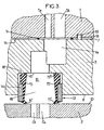
- Rooms 1 and 2 are crossed by channels 5, and 6 strongly offset one with respect to each other ( Figure 1), which are connected to each other so waterproof by a fitting comprising an intermediate block rigid 3, in particular steel.
- This intermediate block 3 is crossed by at least one conduit comprising two sections 4a, 4b with a diameter greater than that of channels 5, 6 and opening respectively into these channels formed in the parts 1 and / or 2.
- the intermediate block 3 may also be made for example of aluminum, plastic (resin of type PA 6-6 or PPS, possibly loaded with glass fibers or the like), or the like.
- One of the faces 7, 8 of the intermediate block 3 which is intended to come into abutment during assembly against one of the support faces 9, 10 of the part 1 (or of the part 2) comprises a sealing device 11, constituted for example by a overmolded elastomer ring, in line with the opening emerging from the conduit 4a.
- the other face 8 of the intermediate block 3 which is intended to bear against one of the bearing faces 9, 10 of Exhibit 2 (or Exhibit 1) has a second sealing device 12.
- the rigid tubular frame 14 outside or inside of insert 13 will prevent any significant deformation, in particular any expansion, of the tube rubber 15 inside or outside ensuring the sealing of the passage.
- the ends of this frame will serve as support for the end beads (15 ', 15' ') of the tube 15, tablets between part 1 or 2 and shoulder 16 produced in the conduit 4a, 4b of the intermediate block 3, this which will maintain the seal at the ends of the fitting waterproof.
- the tubular frame 14 could advantageously be metallic, produced in massive form or even under the form of a braid of metallic threads or mineral fibers or synthetic, if it does not have to be submitted to axial compression forces.
- FIG. 2 which can be substituted for the sealing device 11 (the elastomer ring), a second sealing device 12 (tubular insert), the latter being inserted in a housing of the conduit 4a and resting on one of its beads 15 ', 15' ', at a shoulder.
- the sealing device 11 the elastomer ring
- a second sealing device 12 tubular insert
- connection device identical to that shown in figure 1, but which makes it possible to connect in a sealed manner channels 5a and 5b of the part 1 very close to channels 6a, 6b located in room 2.
- the thickness of the inserts 13 (measured at rest, that is to say that the end beads are not compressed) is greater than the depth of the housing in which comes house said insert, so that when parts 1 and 2 are brought together, the compression of bulges (15 ', 15' ') compensates, as is found in in practice, a large dispersion of block thicknesses intermediate 3, as well as variable play between it and parts 1 and / or 2.
- a positioning device 17 adapted to cooperate by interlocking with at least one of the first and second rigid parts 1, 2. It can be a pawn 18 making projection from the front face 7 or 8 of the block intermediate 3, the latter cooperating at an orifice 18 made on one of parts 1 or 2.
- an outgrowth of material 20, especially in elastomer, came from manufacturing with one beads 15 ', 15' 'located at the end of the insert 13.
- this outgrowth of material 20 is produced on the peripheral external surface of the insert 13 and came during overmolding.
- the protuberance of material 20 is formed by a lip located to the right of the outlet orifice of the housing receiving the insert 13.
- the outgrowth of material 20 generates friction between the insert 13 and a wall of the duct 4a, 4b in which it is housed, thus limiting the movement of the latter.
Abstract
Description
La présente invention est relative aux raccords étanches.The present invention relates to fittings waterproof.
Plus particulièrement, l'invention concerne un raccord étanche destiné à relier entre eux des canaux ménagés respectivement dans des première et deuxième pièces rigides solidarisées l'une à l'autre, ce raccord étanche comprenant au moins un insert tubulaire qui comprend une armature tubulaire rigide s'étendant axialement entre des première et deuxième extrémités ouvertes, lesdites première et deuxième extrémités étant revêtues respectivement de premier et deuxième bourrelets d'élastomère qui font saillie axialement au-delà de l'extrémité correspondante de l'armature tubulaire.More particularly, the invention relates to a tight fitting intended to connect arranged channels to each other respectively in first and second rigid parts secured to each other, this tight fitting comprising at least one tubular insert which includes a frame rigid tubular extending axially between first and second open ends, said first and second ends being respectively coated with first and second elastomeric beads which project axially beyond the corresponding end of the reinforcement tubular.
Il s'agira par exemple de réaliser, grâce à ce raccord, la continuité de canaux de passage d'un fluide dans les deux pièces, généralement séparées par une ou plusieurs entretoises. Dans la pratique ce fluide pourra être de l'huile en circulation sous une pression variable, éventuellement de façon pulsatoire, de 0 à plusieurs dizaines de bars, à température également très variable (- 40 à + 150°C par exemple). Les pièces en question peuvent appartenir à des carters, notamment dans une boíte de vitesses automatiques.For example, this will involve fitting, the continuity of fluid passage channels in the two rooms, generally separated by one or more spacers. In practice, this fluid may be the oil circulating under a variable pressure, possibly pulsating, from 0 to several tens bars, also at very variable temperature (- 40 to + 150 ° C for example). The parts in question may belong to housings, especially in a gearbox automatic.
On connaít par le document FR-A-2 759 756, un raccord étanche du type susmentionné, dans lequel l'insert tubulaire est en appui étanche contre deux surfaces opposées appartenant respectivement aux deux pièces à raccorder. Ce raccord étanche donne toute satisfaction du point de vue de son fonctionnement technique, mais présente néanmoins l'inconvénient de ne pas permettre aisément la liaison entre les canaux de chacune des pièces, lorsque ceux-ci sont décalés : en effet, on est alors conduit à adopter un insert tubulaire de grand diamètre ou de section ovale, encombrant et coûteux.We know from document FR-A-2 759 756, a fitting sealed of the aforementioned type, in which the tubular insert is sealed against two opposite surfaces belonging respectively to the two parts to be connected. This tight fitting gives full satisfaction from the point of view of its technical functioning, but nevertheless presents the disadvantage of not easily allowing the connection between the channels of each of the parts, when these are staggered: indeed, we are then led to adopt an insert tubular large diameter or oval section, bulky and expensive.
De même, lorsque les canaux d'une même pièce sont très rapprochés, les raccords du document FR-A-2 759 756 ne sont pas facilement utilisables, car ils nécessitent un écartement relativement important entre les canaux.Similarly, when the channels of the same room are very close together, the connections of document FR-A-2 759 756 do not are not easily usable because they require a relatively large spacing between the channels.
La présente invention a notamment pour but de pallier ces inconvénients.The object of the present invention is in particular to overcome these drawbacks.
A cet effet, selon l'invention, un raccord du genre en question est caractérisé en ce qu'il comporte en outre un bloc intermédiaire rigide présentant des première et deuxième faces opposées dans lesquelles débouche un conduit traversant ledit bloc intermédiaire, la première face étant dotée d'un dispositif d'étanchéité adapté pour venir en appui étanche contre la première pièce rigide en isolant ledit conduit, le conduit formant un logement cylindrique qui s'étend entre la deuxième face du bloc intermédiaire et un épaulement orienté vers ladite deuxième face, et l'insert tubulaire étant disposé dans ledit logement avec son premier bourrelet en appui axial étanche contre l'épaulement dudit logement et son deuxième bourrelet faisant saillie hors du logement, ce deuxième bourrelet étant destiné à venir en appui étanche contre la deuxième pièce rigide.To this end, according to the invention, a connection of the kind in question is characterized in that it further comprises a rigid intermediate block with first and second opposite faces into which a conduit opens crossing said intermediate block, the first face being with a sealing device adapted to come into waterproof support against the first rigid part by insulating said conduit, the conduit forming a cylindrical housing which extends between the second face of the intermediate block and a shoulder oriented towards said second face, and the insert tubular being disposed in said housing with its first bead in sealed axial support against the shoulder of said housing and its second bead protruding out of the housing, this second bead being intended to come in waterproof support against the second rigid part.
Grâce à ces dispositions, on peut réaliser la connexion étanche entre des canaux cheminant dans des pièces différentes, même lorsque ces canaux sont fortement désaxés : dans ce cas, on peut en effet réaliser un conduit coudé dans le bloc intermédiaire, ce conduit conservant un diamètre relativement faible.Thanks to these arrangements, the tight connection between channels running through rooms different even when these channels are strongly offset: in this case, we can indeed make a conduit bent in the intermediate block, this duct retains a relatively small diameter.
De plus, lorsque les canaux de la première pièce sont très rapprochés l'un de l'autre, on peut : soit percer plusieurs conduits parallèles dans le bloc intermédiaire et prévoir sur la deuxième face dudit bloc intermédiaire de simples joints annulaires en appui sur la première pièce rigide, lorsque les canaux en question correspondent à des flux de liquides qui doivent rester séparés, soit faire déboucher ces canaux dans le même conduit du bloc intermédiaire, dans le cas contraire.In addition, when the channels of the first room are very close to each other, we can: either drill several parallel conduits in the intermediate block and provide on the second face of said intermediate block of simple annular seals supported on the first part rigid, when the channels in question correspond to flow of liquids which must remain separated, either make unblock these channels in the same duct of the block intermediate, otherwise.
Dans des modes de réalisation préférés de l'invention, on peut éventuellement avoir recours en outre aux dispositions suivantes :
- le bourrelet de l'insert comporte en périphérie une excroissance de matière destinée à limiter le coulissement de l'insert dans son logement ;
- le logement comporte en périphérie une excroissance de matière destinée à limiter le coulissement de l'insert ;
- le dispositif d'étanchéité est un anneau en élastomère surmoulé sur la première face du bloc intermédiaire ;
- le dispositif d'étanchéité est un deuxième insert tubulaire logé dans un deuxième logement formé dans le conduit, ledit deuxième insert comprenant une armature tubulaire rigide s'étendant axialement entre des première et deuxième extrémités ouvertes revêtues respectivement de premier et deuxième bourrelets d'élastomère, le premier bourrelet étant en appui d'un épaulement formé dans le deuxième logement et le deuxième bourrelet étant destiné à venir en appui étanche contre la première pièce rigide ;
- le bloc intermédiaire comporte, sur au moins l'une des faces destinées à venir en appui de l'une des première ou seconde pièces, un dispositif de positionnement adapté pour coopérer par emboítement avec au moins l'une des première et deuxième pièces rigides ;
- l'armature tubulaire est revêtue d'une couche continue d'élastomère qui est formée d'une seule pièce avec les premier et deuxième bourrelets ;
- le premier bourrelet d'élastomère est compressible élastiquement sur une distance axiale d'au moins 5 mm.
- the bead of the insert has a protrusion of material at the periphery intended to limit the sliding of the insert in its housing;
- the housing comprises at the periphery a projection of material intended to limit the sliding of the insert;
- the sealing device is an elastomer ring overmolded on the first face of the intermediate block;
- the sealing device is a second tubular insert housed in a second housing formed in the duct, said second insert comprising a rigid tubular frame extending axially between first and second open ends coated with first and second elastomer beads respectively, the first bead being in support of a shoulder formed in the second housing and the second bead being intended to come into sealing abutment against the first rigid part;
- the intermediate block comprises, on at least one of the faces intended to come to bear on one of the first or second parts, a positioning device adapted to cooperate by fitting with at least one of the first and second rigid parts;
- the tubular frame is coated with a continuous layer of elastomer which is formed in one piece with the first and second beads;
- the first bead of elastomer is elastically compressible over an axial distance of at least 5 mm.
D'autres caractéristiques et avantages de l'invention apparaítront au cours de la description suivante de diverses formes de réalisation, donnée à titre d'exemple non limitatif, en regard des dessins joints.Other features and benefits of the invention will appear during the following description of various embodiments, given by way of example not limiting, with reference to the accompanying drawings.
Sur les dessins :
- les figures 1, 2, 3 sont des vues en élévation latérale de trois modes de réalisation différents du raccord étanche objet de l'invention ;
- les figures 4 et 5 sont des vues en détail de l'un des dispositifs d'étanchéité du raccord étanche représenté en figures 1, 2, 3 ;
- la figure 6 est une vue en détail du bord d'un des logements recevant l'insert, formant le dispositif d'étanchéité du raccord étanche.
- Figures 1, 2, 3 are side elevational views of three different embodiments of the tight fitting object of the invention;
- Figures 4 and 5 are detailed views of one of the sealing devices of the sealed connection shown in Figures 1, 2, 3;
- Figure 6 is a detailed view of the edge of one of the housings receiving the insert, forming the sealing device of the sealed connection.
Sur les différentes figures, les mêmes références désignent des éléments identiques ou similaires.In the different figures, the same references denote identical or similar elements.
Sur les figures 1 et 2, on a référencé en 1 et 2 deux pièces écartées d'une distance h dans une zone où doit s'effectuer une liaison étanche entre ces pièces.In Figures 1 and 2, we have referenced 1 and 2 two pieces separated by a distance h in an area where must make a tight connection between these parts.
Les pièces 1 et 2 sont respectivement traversées par
des canaux 5, et 6 fortement désaxés l'un par rapport à
l'autre (figure 1), qui sont reliés l'un à l'autre de façon
étanche par un raccord comprenant un bloc intermédiaire
rigide 3, notamment en acier. Ce bloc intermédiaire 3 est
traversé par au moins un conduit comprenant deux tronçons 4a,
4b de diamètre supérieur à celui des canaux 5, 6 et
débouchant respectivement dans ces canaux ménagés dans les
pièces 1 et/ou 2.
Bien entendu, le bloc intermédiaire 3 pourra aussi
être élaboré par exemple en aluminium, en matière plastique
(résine de type PA 6-6 ou PPS, éventuellement chargés en
fibres de verre ou analogue), ou autre.Of course, the
L'une des faces 7, 8 du bloc intermédiaire 3 qui est
destinée à venir en appui lors du montage contre l'une des
faces 9, 10 d'appui de la pièce 1 (ou de la pièce 2) comporte
un dispositif d'étanchéité 11, constitué par exemple par un
anneau en élastomère surmoulé, au droit de l'orifice
débouchant du conduit 4a.One of the
L'autre face 8 du bloc intermédiaire 3 qui est
destinée à venir en appui contre l'une des faces d'appui 9,
10 de la pièce 2 (ou de la pièce 1) comporte un deuxième
dispositif d'étanchéité 12.The
Ce deuxième dispositif d'étanchéité 12 est réalisé à partir d'un insert tubulaire 13, celui-ci comprenant :
- une armature tubulaire rigide 14; et
- au moins un
tube 15 en caoutchouc ou matière synthétique élastique, revêtant au moins les extrémités de ladite armature et présentant à ses deux extrémités un premier et second bourrelet (15', 15'') recouvrant l'extrémité correspondante de cette armature, ces premier et second bourrelets pouvant ainsi être comprimés (de l'ordre par exemple de 5mm), lors du montage, de façon étanche, entre d'une part, l'une des faces d'appui appartenant aux pièces 1 ou 2 et d'autre part, unépaulement 16 réalisé dans le fond du conduit 4b.
- a rigid
tubular frame 14; and - at least one
tube 15 made of rubber or elastic synthetic material, covering at least the ends of said frame and having at its two ends a first and second bead (15 ', 15'') covering the corresponding end of this frame, these first and second beads which can thus be compressed (of the order for example of 5 mm), during assembly, in a sealed manner, between on the one hand, one of the bearing faces belonging toparts 1 or 2 and on the other share, ashoulder 16 formed in the bottom of the conduit 4b.
On comprend alors que l'armature tubulaire rigide 14
extérieure ou intérieure de l'insert 13 empêchera toute
déformation sensible, notamment toute dilatation, du tube de
caoutchouc 15 intérieur ou extérieur assurant l'étanchéité du
passage. Les extrémités de cette armature serviront quant à
elles d'appuis pour les bourrelets d'extrémité (15', 15'') du
tube 15, comprimés entre la pièce 1 ou 2 et l'épaulement 16
réalisé dans le conduit 4a, 4b du bloc intermédiaire 3, ce
qui maintiendra l'étanchéité aux extrémités du raccord
étanche.We then understand that the rigid
L'armature tubulaire 14 pourra être avantageusement
métallique, réalisée sous forme massive ou encore sous la
forme d'une tresse en fils métalliques ou fibres minérales ou
synthétiques, dans le cas où elle n'aurait pas à être soumise
à des efforts de compression axiaux.The
On comprend aisément, comme représenté en figure 2,
que l'on peut substituer au dispositif d'étanchéité 11
(l'anneau en élastomère), un second dispositif d'étanchéité
12 (insert tubulaire), ce dernier étant inséré dans un
logement du conduit 4a et s'appuyant au niveau de l'un de ses
bourrelets 15', 15'', au niveau d'un épaulement.It is easy to understand, as shown in FIG. 2,
which can be substituted for the sealing device 11
(the elastomer ring), a second sealing device
12 (tubular insert), the latter being inserted in a
housing of the
Par ailleurs, sur la figure 3, on a représenté un
dispositif de liaison identique à celui représenté en figure
1, mais qui permet de mettre en relation de manière étanche
des canaux 5a et 5b de la pièce 1 très rapprochés à des
canaux 6a, 6b situés dans la pièce 2.Furthermore, in Figure 3, there is shown a
connection device identical to that shown in figure
1, but which makes it possible to connect in a sealed
Quel que soit le mode de réalisation, on remarque que
l'épaisseur des inserts 13 (mesurée au repos, c'est-à-dire
que les bourrelets d'extrémité ne sont pas comprimés) est
supérieure à la profondeur du logement dans lequel vient se
loger ledit insert, de sorte que lorsque les pièces 1 et 2
sont rapprochées l'une de l'autre, la compression des
bourrelets (15', 15'') compense, comme cela se rencontre dans
la pratique, une importante dispersion des épaisseurs du bloc
intermédiaire 3, ainsi que des jeux variables entre elle et
les pièces 1 et/ou 2.Whatever the embodiment, we note that
the thickness of the inserts 13 (measured at rest, that is to say
that the end beads are not compressed) is
greater than the depth of the housing in which comes
house said insert, so that when
Par ailleurs, on prévoit de disposer au niveau de
l'une des faces frontales 7, 8 du bloc intermédiaire 3 et de
la face 9 ou 10 en regard appartenant à la pièce 1 ou 2, un
dispositif de positionnement 17, adapté pour coopérer par
emboítement avec au moins l'une des première et deuxième
pièces rigides 1, 2. Il peut s'agir d'un pion 18 faisant
saillie par rapport à la face frontale 7 ou 8 du bloc
intermédiaire 3, ce dernier coopérant au niveau d'un orifice
18 réalisé sur l'une des pièces 1 ou 2.Furthermore, it is planned to have at the level of
one of the
Sur les figures 4, 5, 6, on a représenté différents
modes de réalisation de dispositifs permettant de limiter le
coulissement de l'insert 13 au sein de son logement dans le
conduit 4a, 4b.In Figures 4, 5, 6, there are shown different
embodiments of devices making it possible to limit the
sliding of the
Ainsi en figure 4, une excroissance de matière 20,
notamment en élastomère, est venue de fabrication avec l'un
des bourrelets 15', 15'' situés à l'extrémité de l'insert
13.Thus in FIG. 4, an outgrowth of
En figure 5, cette excroissance de matière 20 est
réalisée sur la surface externe périphérique de l'insert 13
et est venue lors du surmoulage.In FIG. 5, this outgrowth of
En figure 6, l'excroissance de matière 20 est formée
par une lèvre située au droit de l'orifice de sortie du
logement recevant l'insert 13.In FIG. 6, the protuberance of
Quel que soit le mode de réalisation, l'excroissance
de matière 20 permet de générer un frottement entre l'insert
13 et une paroi du conduit 4a, 4b dans lequel il est logé,
limitant ainsi le déplacement de ce dernier.Whatever the embodiment, the outgrowth
of
Claims (8)
- A leaktight coupling for interconnecting channels (5, 5a, 5b, 6, 6a, 6b) formed respectively in first and second rigid pieces (1, 2) that are secured to each other, the leaktight coupling comprising at least one tubular insert (13) including a rigid tubular strength member (14) extending axially between first and second open ends, said first and second ends being covered with respective first and second elastomer beads (15', 15") which project axially beyond the corresponding end of the tubular strength member (14), the coupling being characterized in that it further comprises a rigid intermediate block (3) presenting first and second opposite faces (7, 8) into which a duct (4a, 4b) passing through said intermediate block opens out, the first face (7) being provided with a sealing device (11) for pressing in leaktight manner against the first rigid piece (1) so as to isolate said duct, the duct forming a cylindrical housing which extends between the second face (8) of the intermediate block (3) and a shoulder (16) facing towards said second face, and the tubular insert (13) being disposed in said housing with its first bead (15') bearing axially in leaktight manner against the shoulder (16) of said housing and with its second bead (15") projecting from said housing, said second bead (15") being designed to press in leaktight manner against the second rigid piece (2).
- A connection device according to claim 1, in which the bead (15', 15") of the insert (13) has a peripheral projection of material (20) for limiting sliding of the insert (13) in its housing.
- A connection device according to claim 1, in which the housing has a peripheral projection of material (20) for limiting sliding of the insert (13).
- A connection device according to any one of claims 1 to 3, in which the sealing device (11) is an elastomer ring overmolded on the first face (7) of the intermediate block (3).
- A connection device according to any one of claims 1 to 3, in which the sealing device (11) is a second tubular insert (13) housed in a second housing formed in a duct (4a), said second insert comprising a rigid tubular strength member (14) extending axially between first and second open ends covered respectively in first and second elastomer beads (15', 15"), the first bead (15') pressing against a shoulder (16) formed in the second housing, and the second bead (15") being for pressing in leaktight manner against the first rigid piece (1).
- A connection device according to any one of claims 1 to 5, in which the intermediate block (3) includes a positioning device (17) on one of its faces (7, 8) for bearing against one of the pieces (1, 2), the positioning device being adapted to co-operate by engaging with at least one of the first and second rigid pieces (1, 2).
- A connection device according to any one of claims 1 to 6, in which the tubular strength member (14) is provided with a continuous elastomer layer which is formed integrally with the first and second beads (15', 15").
- A connection device according to any one of claims 1 to 7, in which the first elastomer bead (15") is elastically compressible over an axial distance of at least 5 mm.
Applications Claiming Priority (2)
| Application Number | Priority Date | Filing Date | Title |
|---|---|---|---|
| FR0104639 | 2001-04-05 | ||
| FR0104639A FR2823283B1 (en) | 2001-04-05 | 2001-04-05 | WATERPROOF FITTING |
Publications (2)
| Publication Number | Publication Date |
|---|---|
| EP1248028A1 EP1248028A1 (en) | 2002-10-09 |
| EP1248028B1 true EP1248028B1 (en) | 2004-12-15 |
Family
ID=8861980
Family Applications (1)
| Application Number | Title | Priority Date | Filing Date |
|---|---|---|---|
| EP02290796A Expired - Lifetime EP1248028B1 (en) | 2001-04-05 | 2002-03-29 | Leak-proof coupling |
Country Status (6)
| Country | Link |
|---|---|
| US (1) | US6767017B2 (en) |
| EP (1) | EP1248028B1 (en) |
| AT (1) | ATE285048T1 (en) |
| DE (1) | DE60202233T2 (en) |
| ES (1) | ES2234991T3 (en) |
| FR (1) | FR2823283B1 (en) |
Families Citing this family (24)
| Publication number | Priority date | Publication date | Assignee | Title |
|---|---|---|---|---|
| ITTO20040249A1 (en) * | 2004-04-22 | 2004-07-22 | Gevipi Ag | HYDRAULIC SEALING DEVICE WITH SLEEVE |
| WO2006008856A1 (en) * | 2004-07-16 | 2006-01-26 | Ckd Corporation | Seal structure, fluid apparatus, integrated valve, and seal member |
| US7448653B2 (en) | 2005-06-10 | 2008-11-11 | Value Plastics, Inc. | Female connector for releasable coupling with a male connector defining a fluid conduit |
| WO2007011883A2 (en) * | 2005-07-18 | 2007-01-25 | Kalsi Engineering, Inc. | Filled hydrodynamic seal with contact pressure control, anti-rotation and filler retention |
| US7806139B2 (en) | 2006-01-20 | 2010-10-05 | Value Plastics, Inc. | Fluid conduit coupling assembly having male and female couplers with integral valves |
| JP5194002B2 (en) * | 2007-04-18 | 2013-05-08 | イーグル工業株式会社 | gasket |
| USD654573S1 (en) | 2007-11-19 | 2012-02-21 | Value Plastics, Inc. | Female quick connect fitting |
| US8235426B2 (en) | 2008-07-03 | 2012-08-07 | Nordson Corporation | Latch assembly for joining two conduits |
| USD655393S1 (en) | 2009-06-23 | 2012-03-06 | Value Plastics, Inc. | Multi-port valve |
| US10711930B2 (en) | 2009-12-09 | 2020-07-14 | Nordson Corporation | Releasable connection assembly |
| USD649240S1 (en) | 2009-12-09 | 2011-11-22 | Value Plastics, Inc. | Male dual lumen bayonet connector |
| USD783815S1 (en) | 2009-12-09 | 2017-04-11 | General Electric Company | Male dual lumen bayonet connector |
| US9388929B2 (en) | 2009-12-09 | 2016-07-12 | Nordson Corporation | Male bayonet connector |
| USD650478S1 (en) | 2009-12-23 | 2011-12-13 | Value Plastics, Inc. | Female dual lumen connector |
| JP5714028B2 (en) | 2009-12-23 | 2015-05-07 | ノードソン コーポレーションNordson Corporation | Fluid connector latch with profile retraction |
| JP5814257B2 (en) | 2009-12-23 | 2015-11-17 | ノードソン コーポレーションNordson Corporation | Button latch with integrally molded cantilever spring |
| USD652511S1 (en) | 2011-02-11 | 2012-01-17 | Value Plastics, Inc. | Female body of connector for fluid tubing |
| USD652510S1 (en) | 2011-02-11 | 2012-01-17 | Value Plastics, Inc. | Connector for fluid tubing |
| USD663022S1 (en) | 2011-02-11 | 2012-07-03 | Nordson Corporation | Male body of connector for fluid tubing |
| USD698440S1 (en) | 2011-07-29 | 2014-01-28 | Nordson Corporation | Connector for fluid tubing |
| USD699841S1 (en) | 2011-07-29 | 2014-02-18 | Nordson Corporation | Female body of connector for fluid tubing |
| USD699840S1 (en) | 2011-07-29 | 2014-02-18 | Nordson Corporation | Male body of connector for fluid tubing |
| USD709612S1 (en) | 2011-12-23 | 2014-07-22 | Nordson Corporation | Female dual lumen connector |
| USD838366S1 (en) | 2016-10-31 | 2019-01-15 | Nordson Corporation | Blood pressure connector |
Family Cites Families (6)
| Publication number | Priority date | Publication date | Assignee | Title |
|---|---|---|---|---|
| US3340774A (en) * | 1965-07-13 | 1967-09-12 | Arthur M Brenneke | Combination cylinder sleeve or liner and combustion chamber seal |
| US3570374A (en) * | 1969-03-19 | 1971-03-16 | Caterpillar Tractor Co | Cylinder head gasket |
| US3929356A (en) * | 1974-11-13 | 1975-12-30 | Gen Motors Corp | Tube to block mounting assembly |
| DE3922885A1 (en) * | 1989-07-12 | 1991-01-17 | Man Nutzfahrzeuge Ag | CYLINDER HEAD GASKET FOR PISTON PISTON, IN PARTICULAR COMBUSTION ENGINES |
| FR2759756B1 (en) | 1997-02-20 | 1999-04-23 | Hutchinson | WATERPROOF CONNECTION DEVICE BETWEEN CHANNELS |
| WO2000075538A1 (en) * | 1999-06-03 | 2000-12-14 | Caterpillar Inc. | A fluid passage seal |
-
2001
- 2001-04-05 FR FR0104639A patent/FR2823283B1/en not_active Expired - Lifetime
-
2002
- 2002-03-29 ES ES02290796T patent/ES2234991T3/en not_active Expired - Lifetime
- 2002-03-29 EP EP02290796A patent/EP1248028B1/en not_active Expired - Lifetime
- 2002-03-29 DE DE60202233T patent/DE60202233T2/en not_active Expired - Fee Related
- 2002-03-29 AT AT02290796T patent/ATE285048T1/en not_active IP Right Cessation
- 2002-04-04 US US10/116,533 patent/US6767017B2/en not_active Expired - Fee Related
Also Published As
| Publication number | Publication date |
|---|---|
| US20020153670A1 (en) | 2002-10-24 |
| FR2823283A1 (en) | 2002-10-11 |
| ATE285048T1 (en) | 2005-01-15 |
| US6767017B2 (en) | 2004-07-27 |
| EP1248028A1 (en) | 2002-10-09 |
| DE60202233T2 (en) | 2005-12-08 |
| ES2234991T3 (en) | 2005-07-01 |
| DE60202233D1 (en) | 2005-01-20 |
| FR2823283B1 (en) | 2003-06-27 |
Similar Documents
| Publication | Publication Date | Title |
|---|---|---|
| EP1248028B1 (en) | Leak-proof coupling | |
| EP0860636B1 (en) | Tight connection between conduits | |
| EP0541472B1 (en) | Locked joint for canalisations | |
| EP2882487B1 (en) | Connector for medical use | |
| FR2782772A1 (en) | SINGLE-BODY SNAP-ON CONNECTOR | |
| WO2003025449A1 (en) | Single-piece snap-on connection | |
| EP0348267A1 (en) | Composite seals for hydraulic systems | |
| FR2580035A1 (en) | ||
| FR2868499A1 (en) | QUICK COUPLING | |
| FR2576658A1 (en) | SEALING STRUCTURE | |
| EP2162663A2 (en) | Connector with improved outer washing | |
| FR2703753A1 (en) | Quick-fit gland (stuffing box) | |
| CA3018006A1 (en) | Dynamic seal device | |
| FR2692334A1 (en) | Assembly and cutting tool for forming branch pipe in situ - comprising upper tube containing drive fitted perpendicular to main pipe walls, and lower part with cutting tool and containing saddle clamping to main pipe | |
| EP0392908A1 (en) | Joint for pipes | |
| FR2520478A1 (en) | SELF-CLOSING COUPLER, PARTICULARLY FOR FLUID OR REFRIGERANT | |
| EP0918183B1 (en) | Joint, particularly for fiber-glass pipes | |
| FR2683292A1 (en) | Connection between two ends of tubes | |
| BE1004574A3 (en) | Method for connecting a pipe in the wall of concrete tank. | |
| KR101676739B1 (en) | Seamed pipe for double fixed for a sewer pipe connection | |
| JPH07280108A (en) | Pinch valve | |
| FR2673263A1 (en) | Assembly forming a seal for flexible connection between two elements | |
| FR2814597A1 (en) | Sealing arrangement for electrical in-line connector, comprises plug element having series ribbed convolutions to provide tight seal | |
| CH696598A5 (en) | seal flange against leakage to connect pipes having different outer diameters and smooth ends. | |
| FR2633961A1 (en) | SYSTEM OF EVACUATION OF RAINWATER |
Legal Events
| Date | Code | Title | Description |
|---|---|---|---|
| PUAI | Public reference made under article 153(3) epc to a published international application that has entered the european phase |
Free format text: ORIGINAL CODE: 0009012 |
|
| AK | Designated contracting states |
Kind code of ref document: A1 Designated state(s): AT BE CH CY DE DK ES FI FR GB GR IE IT LI LU MC NL PT SE TR |
|
| AX | Request for extension of the european patent |
Free format text: AL;LT;LV;MK;RO;SI |
|
| 17P | Request for examination filed |
Effective date: 20020920 |
|
| AKX | Designation fees paid |
Designated state(s): AT BE CH CY DE DK ES FI FR GB GR IE IT LI LU MC NL PT SE TR |
|
| GRAP | Despatch of communication of intention to grant a patent |
Free format text: ORIGINAL CODE: EPIDOSNIGR1 |
|
| GRAS | Grant fee paid |
Free format text: ORIGINAL CODE: EPIDOSNIGR3 |
|
| GRAA | (expected) grant |
Free format text: ORIGINAL CODE: 0009210 |
|
| AK | Designated contracting states |
Kind code of ref document: B1 Designated state(s): AT BE CH CY DE DK ES FI FR GB GR IE IT LI LU MC NL PT SE TR |
|
| PG25 | Lapsed in a contracting state [announced via postgrant information from national office to epo] |
Ref country code: AT Free format text: LAPSE BECAUSE OF FAILURE TO SUBMIT A TRANSLATION OF THE DESCRIPTION OR TO PAY THE FEE WITHIN THE PRESCRIBED TIME-LIMIT Effective date: 20041215 Ref country code: TR Free format text: LAPSE BECAUSE OF FAILURE TO SUBMIT A TRANSLATION OF THE DESCRIPTION OR TO PAY THE FEE WITHIN THE PRESCRIBED TIME-LIMIT Effective date: 20041215 Ref country code: IE Free format text: LAPSE BECAUSE OF FAILURE TO SUBMIT A TRANSLATION OF THE DESCRIPTION OR TO PAY THE FEE WITHIN THE PRESCRIBED TIME-LIMIT Effective date: 20041215 Ref country code: NL Free format text: LAPSE BECAUSE OF FAILURE TO SUBMIT A TRANSLATION OF THE DESCRIPTION OR TO PAY THE FEE WITHIN THE PRESCRIBED TIME-LIMIT Effective date: 20041215 Ref country code: FI Free format text: LAPSE BECAUSE OF FAILURE TO SUBMIT A TRANSLATION OF THE DESCRIPTION OR TO PAY THE FEE WITHIN THE PRESCRIBED TIME-LIMIT Effective date: 20041215 |
|
| REG | Reference to a national code |
Ref country code: GB Ref legal event code: FG4D Free format text: NOT ENGLISH Ref country code: CH Ref legal event code: EP |
|
| REG | Reference to a national code |
Ref country code: IE Ref legal event code: FG4D Free format text: FRENCH |
|
| REF | Corresponds to: |
Ref document number: 60202233 Country of ref document: DE Date of ref document: 20050120 Kind code of ref document: P |
|
| PGFP | Annual fee paid to national office [announced via postgrant information from national office to epo] |
Ref country code: ES Payment date: 20050301 Year of fee payment: 4 |
|
| PG25 | Lapsed in a contracting state [announced via postgrant information from national office to epo] |
Ref country code: DK Free format text: LAPSE BECAUSE OF FAILURE TO SUBMIT A TRANSLATION OF THE DESCRIPTION OR TO PAY THE FEE WITHIN THE PRESCRIBED TIME-LIMIT Effective date: 20050315 Ref country code: GR Free format text: LAPSE BECAUSE OF FAILURE TO SUBMIT A TRANSLATION OF THE DESCRIPTION OR TO PAY THE FEE WITHIN THE PRESCRIBED TIME-LIMIT Effective date: 20050315 Ref country code: SE Free format text: LAPSE BECAUSE OF FAILURE TO SUBMIT A TRANSLATION OF THE DESCRIPTION OR TO PAY THE FEE WITHIN THE PRESCRIBED TIME-LIMIT Effective date: 20050315 |
|
| PG25 | Lapsed in a contracting state [announced via postgrant information from national office to epo] |
Ref country code: LU Free format text: LAPSE BECAUSE OF NON-PAYMENT OF DUE FEES Effective date: 20050329 Ref country code: CY Free format text: LAPSE BECAUSE OF FAILURE TO SUBMIT A TRANSLATION OF THE DESCRIPTION OR TO PAY THE FEE WITHIN THE PRESCRIBED TIME-LIMIT Effective date: 20050329 |
|
| PG25 | Lapsed in a contracting state [announced via postgrant information from national office to epo] |
Ref country code: BE Free format text: LAPSE BECAUSE OF NON-PAYMENT OF DUE FEES Effective date: 20050331 Ref country code: MC Free format text: LAPSE BECAUSE OF NON-PAYMENT OF DUE FEES Effective date: 20050331 |
|
| GBT | Gb: translation of ep patent filed (gb section 77(6)(a)/1977) |
Effective date: 20050318 |
|
| NLV1 | Nl: lapsed or annulled due to failure to fulfill the requirements of art. 29p and 29m of the patents act | ||
| REG | Reference to a national code |
Ref country code: ES Ref legal event code: FG2A Ref document number: 2234991 Country of ref document: ES Kind code of ref document: T3 |
|
| REG | Reference to a national code |
Ref country code: IE Ref legal event code: FD4D |
|
| BERE | Be: lapsed |
Owner name: HUTCHINSON Effective date: 20050331 |
|
| PLBE | No opposition filed within time limit |
Free format text: ORIGINAL CODE: 0009261 |
|
| STAA | Information on the status of an ep patent application or granted ep patent |
Free format text: STATUS: NO OPPOSITION FILED WITHIN TIME LIMIT |
|
| 26N | No opposition filed |
Effective date: 20050916 |
|
| PGFP | Annual fee paid to national office [announced via postgrant information from national office to epo] |
Ref country code: DE Payment date: 20060307 Year of fee payment: 5 Ref country code: GB Payment date: 20060307 Year of fee payment: 5 |
|
| PGFP | Annual fee paid to national office [announced via postgrant information from national office to epo] |
Ref country code: FR Payment date: 20060323 Year of fee payment: 5 |
|
| PG25 | Lapsed in a contracting state [announced via postgrant information from national office to epo] |
Ref country code: LI Free format text: LAPSE BECAUSE OF NON-PAYMENT OF DUE FEES Effective date: 20060331 Ref country code: CH Free format text: LAPSE BECAUSE OF NON-PAYMENT OF DUE FEES Effective date: 20060331 |
|
| PGFP | Annual fee paid to national office [announced via postgrant information from national office to epo] |
Ref country code: IT Payment date: 20060331 Year of fee payment: 5 |
|
| REG | Reference to a national code |
Ref country code: CH Ref legal event code: PL |
|
| GBPC | Gb: european patent ceased through non-payment of renewal fee |
Effective date: 20070329 |
|
| BERE | Be: lapsed |
Owner name: *HUTCHINSON Effective date: 20050331 |
|
| PG25 | Lapsed in a contracting state [announced via postgrant information from national office to epo] |
Ref country code: PT Free format text: LAPSE BECAUSE OF NON-PAYMENT OF DUE FEES Effective date: 20050515 |
|
| REG | Reference to a national code |
Ref country code: FR Ref legal event code: ST Effective date: 20071130 |
|
| PG25 | Lapsed in a contracting state [announced via postgrant information from national office to epo] |
Ref country code: DE Free format text: LAPSE BECAUSE OF NON-PAYMENT OF DUE FEES Effective date: 20071002 |
|
| PG25 | Lapsed in a contracting state [announced via postgrant information from national office to epo] |
Ref country code: GB Free format text: LAPSE BECAUSE OF NON-PAYMENT OF DUE FEES Effective date: 20070329 |
|
| REG | Reference to a national code |
Ref country code: ES Ref legal event code: FD2A Effective date: 20070330 |
|
| PG25 | Lapsed in a contracting state [announced via postgrant information from national office to epo] |
Ref country code: FR Free format text: LAPSE BECAUSE OF NON-PAYMENT OF DUE FEES Effective date: 20070402 Ref country code: ES Free format text: LAPSE BECAUSE OF NON-PAYMENT OF DUE FEES Effective date: 20070330 |
|
| PG25 | Lapsed in a contracting state [announced via postgrant information from national office to epo] |
Ref country code: IT Free format text: LAPSE BECAUSE OF NON-PAYMENT OF DUE FEES Effective date: 20070329 |