EP0392908A1 - Joint for pipes - Google Patents
Joint for pipes Download PDFInfo
- Publication number
- EP0392908A1 EP0392908A1 EP90400952A EP90400952A EP0392908A1 EP 0392908 A1 EP0392908 A1 EP 0392908A1 EP 90400952 A EP90400952 A EP 90400952A EP 90400952 A EP90400952 A EP 90400952A EP 0392908 A1 EP0392908 A1 EP 0392908A1
- Authority
- EP
- European Patent Office
- Prior art keywords
- piping
- locking
- tabs
- connection
- tubing
- Prior art date
- Legal status (The legal status is an assumption and is not a legal conclusion. Google has not performed a legal analysis and makes no representation as to the accuracy of the status listed.)
- Withdrawn
Links
- 229920002994 synthetic fiber Polymers 0.000 claims abstract description 4
- 238000012423 maintenance Methods 0.000 claims description 6
- 238000000465 moulding Methods 0.000 claims description 4
- 239000004033 plastic Substances 0.000 claims description 3
- 229920003002 synthetic resin Polymers 0.000 claims 1
- 239000000057 synthetic resin Substances 0.000 claims 1
- 210000000078 claw Anatomy 0.000 abstract 3
- 230000000903 blocking effect Effects 0.000 description 5
- 239000000446 fuel Substances 0.000 description 3
- XLYOFNOQVPJJNP-UHFFFAOYSA-N water Substances O XLYOFNOQVPJJNP-UHFFFAOYSA-N 0.000 description 3
- 238000007789 sealing Methods 0.000 description 2
- 210000002105 tongue Anatomy 0.000 description 2
- 208000031968 Cadaver Diseases 0.000 description 1
- 239000004959 Rilsan Substances 0.000 description 1
- 230000008878 coupling Effects 0.000 description 1
- 238000010168 coupling process Methods 0.000 description 1
- 238000005859 coupling reaction Methods 0.000 description 1
- 230000008014 freezing Effects 0.000 description 1
- 238000007710 freezing Methods 0.000 description 1
- 239000002828 fuel tank Substances 0.000 description 1
- 238000002347 injection Methods 0.000 description 1
- 239000007924 injection Substances 0.000 description 1
- 239000000463 material Substances 0.000 description 1
- 239000011347 resin Substances 0.000 description 1
- 229920005989 resin Polymers 0.000 description 1
Images

Classifications
-
- F—MECHANICAL ENGINEERING; LIGHTING; HEATING; WEAPONS; BLASTING
- F16—ENGINEERING ELEMENTS AND UNITS; GENERAL MEASURES FOR PRODUCING AND MAINTAINING EFFECTIVE FUNCTIONING OF MACHINES OR INSTALLATIONS; THERMAL INSULATION IN GENERAL
- F16L—PIPES; JOINTS OR FITTINGS FOR PIPES; SUPPORTS FOR PIPES, CABLES OR PROTECTIVE TUBING; MEANS FOR THERMAL INSULATION IN GENERAL
- F16L37/00—Couplings of the quick-acting type
- F16L37/08—Couplings of the quick-acting type in which the connection between abutting or axially overlapping ends is maintained by locking members
- F16L37/12—Couplings of the quick-acting type in which the connection between abutting or axially overlapping ends is maintained by locking members using hooks, pawls or other movable or insertable locking members
Definitions
- the present invention relates to a connection system for smooth pipes and tubes intended more particularly for the automotive industry.
- connection systems must meet a certain number of imperative requirements, among which we can cite: - very high reliability to avoid any cause of failure resulting from the defectiveness of such fittings; - a great aptitude for rapid assembly and disassembly so as to facilitate maintenance operations; - Excellent sealing, in particular both with water and with air, so as to avoid, on the one hand, any introduction of air into the pipes thus connected, this introduction of air resulting in a power failure of the engine when the pipes are those of the fuel supply circuit and on the other hand any introduction of water into the pipes which is a cause of freezing at low temperatures which also results in a fuel supply failure of the motor ; - a low cost price.
- connection systems sold in particular for the applications mentioned above and which are made of synthetic material, in particular "Rilsan”.
- Rubberan synthetic material
- the subject of the present invention is a fitting for piping, in particular for the automobile industry, characterized in that it consists of a body of synthetic material extended by means ensuring the connection either on a pipe or directly on a reservoir or the like and provided with an axial bore provided with a portion of tubing forming a male connecting element for the piping to be connected and on which said piping engages, in that said portion of tubing has a lower part whose outer surface is frustoconical to ensure the maintenance of said piping whose end abuts on the bottom of said bore and in that said bore axial opens on each side of said body according to two lateral windows in which are positioned legs articulated on said body and designed so as to block said piping after its connection to said portion of tubing, said locking tabs coming from molding with said body, so as to obtain a one-piece connection.
- the locking tabs are articulated on the body by means of thin tabs forming hinges, molded with the whole of the connector.
- These locking tabs have recesses in the form of cylindrical cradles which are applied against the facing surfaces of the piping to be connected when the tabs are positioned in the respective windows provided for this purpose in the body of the fitting, the tabs being in further provided with locking means which cooperate with corresponding means provided on the body of the connector.
- the locking means provided on the locking tabs are produced in the form of a clipping system, the corresponding elements of which are respectively provided at the end of each locking part and on the body.
- the connector according to the present invention essentially comprises a body 10 having substantially the shape of an elliptical cylinder and which is extended by means 12 ensuring the connection on a pipe (not shown in the drawing) .
- This set is made of a plastic material, in particular a systhetic resin for example in "Rislan".
- the body is provided with an axial bore 16 which comprises a portion of tubing 14 which, as will be seen below, constitutes a male connecting element for the smooth pipe 18 to be connected to the pipe mounted on the fitting by means 12.
- This axial bore 16 opens on each side of the body (FIG. 1) by means of two side windows 20, 20 ′.
- the portion of tubing 14 on which the smooth piping 18 engages for its connection has a lower part 14 ′ whose outer surface is of frustoconical shape. As will be seen below, this profile of the portion of tubing 14 ensures the maintenance of the piping 18 on the connection system as well as the sealing.
- the body 10 is moreover provided with two tabs 22, 22 ′, which are designed and produced so as to block the piping 18 after its connection to the portion of tubing 14, these blocking tabs which come from molding with the body 10 coming to be positioned in the side windows 20, 20 ′ as will be described below.
- each locking tab such as 22, 22 ′ is articulated on the body 10 using a thin tongue forming a hinge 26, 26 ′ respectively, these hinges coming from molding with the whole fitting.
- Each locking tab is provided with a recess which in this embodiment has the form of a cylindrical cradle 28, 28 ′ respectively and which is intended to come to bear against the corresponding surface of the piping 18 to be connected, when the locking tabs 22, 22 ′ are positioned in their respective windows 20, 20 ′.
- said locking tabs are provided with locking means which are designed so as to cooperate with corresponding means provided on the body of the connector 10.
- the locking means are produced in the form of a clipping system, the corresponding elements of which are provided on the one hand at the end of each locking tab 22, 22 ′ (elements 30, 30 ′) and on the other hand on the body 10 (elements 32, 32 ′).
- the fitting system described above is implemented as follows: - The user sets up the connector body 10 on the pipe to be connected by introducing the end 12 of the connector body into the internal bore of this pipe, or by directly fixing the connector, for example on a tank, the end 12 in fir tail of the embodiment illustrated by the drawings then being replaced by a threaded tail which is connected directly to the tank. Then, it introduces the piping 18 to be connected into the axial bore 16 of the body 10 in the space between the tubing portion 14 and the internal cylindrical surface of this bore. The piping 18 is therefore introduced onto the portion of tubing forming a male connecting element 14 by applying against the external surface of this element 14.
- the frustoconical shape of the lower part 14 ′ of this portion of tubing 14 makes it possible to obtain a blocking of the piping 18 in the body of the fitting, when the piping 18 is forced into the tubing portion 14 until the end of the pipe 18 abuts against the bottom 24 of the 'axial bore 16; - After this establishment of the piping 18 on the body of the connector, the user folds each locking tab 22, 22 ′ towards the body 10 by pivoting around the tongues 26, 26 ′ forming grooves.
- each locking tab is positioned in the corresponding side window 20, 20 ′ provided in the body 10 of the connector, its recess in the form of a cylindrical cradle 28, 28 ′ coming to bear against the opposite surfaces of the piping 18 and, finally, the clipping system 30, 30′-32, 32 ′ ensures the locking of the locking tabs 22, 22 ′ in their housing of the body 10, which completes the blocking of the piping 18 in the fitting .
- connection system makes it possible to produce a one-piece connection, very easy to handle and to implement and ensuring rapid connection, efficient, reliable and watertight of the two smooth pipes to be connected, or of a pipe and a tank, or the like in the case specified above where the connector is directly mounted by screwing on such a tank or equivalent.
- the piping 18 is held on the body 10 by its blocking on the portion of tubing 14 in the bore 16 of the body 10, its end abutting the bottom 24 of this axial bore, which ensures the tightness of the connection both screw -with respect to air than with respect to water, the tabs 22, 22 ′ also make it possible to obtain the maintenance of this seal by blocking any relative movement of the piping 18 relative to the body 10 of the fitting.
- the connector is easily removable which facilitates maintenance operations, since the locking tabs 22, 22 ′ can be unlocked from the body 10, the piping 18 then being detached from the connector by traction.
Abstract
Description
La présente invention concerne un système de raccord pour tuyauteries et tubulures lisses destiné plus particulièrement à l'industrie automobile. On sait que dans cette industrie on utilise de nombreux raccords, un exemple d'une telle utilisation résidant dans la liaison entre la conduite venant d'un réservoir de carburant et le système d'alimentation ou d'injection du carburant dans les cylindres du moteur.The present invention relates to a connection system for smooth pipes and tubes intended more particularly for the automotive industry. We know that in this industry we use many fittings, an example of such a use residing in the connection between the line coming from a fuel tank and the fuel supply or injection system in the engine cylinders .
Ces systèmes de raccord doivent répondre à un certain nombre d'exigences impératives parmi lesquelles on peut citer :
- une très grande fiabilité pour éviter toute cause de panne résultant de la défectuosité de tels raccords ;
- une grande aptitude au montage et au démontage rapides de manière à faciliter les opérations d'entretien;
- une excellente étanchéité en particulier tant à l'eau qu'à l'air, de façon à éviter d'une part toute introduction d'air dans les tubulures ainsi raccordées, cette introduction d'air se traduisant par une panne d'alimentation du moteur lorsque les tubulures sont celles du circuit d'alimentation en carburant et d'autre part toute introduction d'eau dans les tubulures laquelle est une cause de gel lors des basses températures ce qui se traduit également par une panne d'alimentation en carburant du moteur ;
- un faible prix de revient.These connection systems must meet a certain number of imperative requirements, among which we can cite:
- very high reliability to avoid any cause of failure resulting from the defectiveness of such fittings;
- a great aptitude for rapid assembly and disassembly so as to facilitate maintenance operations;
- Excellent sealing, in particular both with water and with air, so as to avoid, on the one hand, any introduction of air into the pipes thus connected, this introduction of air resulting in a power failure of the engine when the pipes are those of the fuel supply circuit and on the other hand any introduction of water into the pipes which is a cause of freezing at low temperatures which also results in a fuel supply failure of the motor ;
- a low cost price.
On connait (EP-A-00 73 892 et EP-A-00 86 900) des systèmes de raccords pour tubes annelés qui sont réalisés sous la forme d'un corps en matière plastique pourvu d'un alésage axial destiné à recevoir les tubes à raccorder et d'un organe de verrouillage mobile venant en prise sur les anneaux des tubes, afin d'assurer leur verrouillage. Ces raccords connus, outre leur application spécifique les rendant impropres à une utilisation sur tubes lisses, ne répondent pas aux exigences mentionnées ci-dessus.There are known (EP-A-00 73 892 and EP-A-00 86 900) connection systems for corrugated tubes which are produced in the form of a plastic body provided with an axial bore intended to receive the tubes. to be connected and a movable locking member engaging on the rings of the tubes, in order to ensure their locking. These known fittings, in addition to their specific application making them unsuitable for use on smooth tubes, do not meet the requirements mentioned above.
Il existe par ailleurs à l'heure actuelle des systèmes de raccord, commercialisés notamment pour les applications mentionnées ci-dessus et qui sont réalisés en matières synthétique notamment en "Rilsan". Malheureusement, ces systèmes de raccord connus ne répondent pas à toutes les exigences mentionnées ci-dessus. Compte-tenu des besoins importants, notamment de l'industrie automobile, la présente titulaire a mis au point un nouveau type de raccord objet de la présente invention et qui répond à l'ensemble des prescriptions définies ci-dessus.At the present time there are also connection systems, sold in particular for the applications mentioned above and which are made of synthetic material, in particular "Rilsan". Unfortunately, these known connection systems do not meet all the requirements mentioned above. Given the significant needs, in particular of the automobile industry, the present licensee has developed a new type of fitting which is the subject of the present invention and which meets all the requirements defined above.
En conséquence, la présente invention a pour objet un raccord pour tuyauterie, notamment pour l'industrie automobile, caractérisé en ce qu'il est constitué d'un corps en matériau synthétique prolongé par un moyen assurant le raccordement soit sur une conduite soit directement sur un réservoir ou similaire et muni d'un alésage axial pourvu d'une portion de tubulure formant élément de liaison mâle pour la tuyauterie à raccorder et sur laquelle s'engage ladite tuyauterie, en ce que ladite portion de tubulure comporte une partie inférieure dont la surface extérieure est tronconique pour assurer le maintien de ladite tuyauterie dont l'extrémité vient en butée sur le fond dudit alésage et en ce que ledit alésage axial débouche de chaque côté dudit corps selon deux fenêtres latérales dans lesquelles viennent se positionner des pattes articulées sur ledit corps et conçues de façon à assurer le blocage de ladite tuyauterie après son raccordement sur ladite portion de tubulure, lesdites pattes de blocage venant de moulage avec ledit corps, de manière à obtenir un raccord monobloc.Consequently, the subject of the present invention is a fitting for piping, in particular for the automobile industry, characterized in that it consists of a body of synthetic material extended by means ensuring the connection either on a pipe or directly on a reservoir or the like and provided with an axial bore provided with a portion of tubing forming a male connecting element for the piping to be connected and on which said piping engages, in that said portion of tubing has a lower part whose outer surface is frustoconical to ensure the maintenance of said piping whose end abuts on the bottom of said bore and in that said bore axial opens on each side of said body according to two lateral windows in which are positioned legs articulated on said body and designed so as to block said piping after its connection to said portion of tubing, said locking tabs coming from molding with said body, so as to obtain a one-piece connection.
Selon une caractéristique de cette invention les pattes de blocage sont articulées sur le corps par l'intermédiaire de languettes de faible épaisseur formant charnières, venues de moulage avec l'ensemble du raccord. Ces pattes de blocage comportent des évidements en forme de berceaux cylindriques venant s'appliquer contre les surfaces en regard de la tuyauterie à raccorder lorsque les pattes viennent se positionner dans les fenêtres respectives prévues à cet effet dans le corps du raccord, les pattes étant en outre munies de moyens de verrouillage qui coopèrent avec des moyens correspondants prévus sur le corps du raccord.According to a characteristic of this invention, the locking tabs are articulated on the body by means of thin tabs forming hinges, molded with the whole of the connector. These locking tabs have recesses in the form of cylindrical cradles which are applied against the facing surfaces of the piping to be connected when the tabs are positioned in the respective windows provided for this purpose in the body of the fitting, the tabs being in further provided with locking means which cooperate with corresponding means provided on the body of the connector.
Selon un exemple de réalisation de l'invention, les moyens de verrouillage prévus sur les pattes de blocage sont réalisés sous la forme d'un système de clipsage dont les éléments correspondants sont respectivement prévus à l'extrémité de chaque partie de blocage et sur le corps.According to an exemplary embodiment of the invention, the locking means provided on the locking tabs are produced in the form of a clipping system, the corresponding elements of which are respectively provided at the end of each locking part and on the body.
D'autres caractéristiques et avantages de la présente invention ressortiront de la description faite ci-après en référence aux dessins annexés qui en illustrent un exemple de réalisation dépourvu de tout caractère limitatif. Sur les dessins :
- la figure 1 est une vue en perspective du système de raccord selon la présente invention avec ses pattes de blocage en position ouverte ;
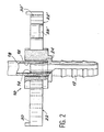
- - la figure 2 est une vue en plan avec coupe horizontale du corps du raccord en partie droite et ;
- - la figure 3 est une vue en bout du système de raccord illustré par les figures 1 et 2, la partie de droite de cette figure étant représentée en coupe verticale.
- Figure 1 is a perspective view of the coupling system according to the present invention with its locking tabs in the open position;
- - Figure 2 is a plan view with horizontal section of the body of the fitting in the straight part and;
- - Figure 3 is an end view of the connection system illustrated in Figures 1 and 2, the right part of this figure being shown in vertical section.
En se référant aux dessins, on voit que le raccord selon la présente invention comprend essentiellement un corps 10 ayant sensiblement la forme d'un cylindre elliptique et qui est prolongé par un moyen 12 assurant le raccordement sur une conduite (non représentée sur le dessin). Cet ensemble est réalisé en une matière plastique, notamment une résine systhétique par exemple en "Rislan". Le corps est muni d'un alésage axial 16 qui comporte une portion de tubulure 14 qui, ainsi qu'on le verra ci-après, constitue un élément de liaison mâle pour la tuyauterie lisse 18 devant être raccordée sur la conduite montée sur le raccord par l'intermédiaire du moyen 12. Cet alésage axial 16 débouche de chaque côté du corps (figure 1) par l'intermédiaire de deux fenêtres latérales 20, 20′.Referring to the drawings, it can be seen that the connector according to the present invention essentially comprises a
Dans cet exemple de réalisation, la portion de tubulure 14 sur laquelle vient s'engager pour son raccordement la tuyauterie lisse 18 présente une partie inférieure 14′ dont la surface extérieure est de forme tronconique. Comme on le verra ci-après ce profil de la portion de tubulure 14 assure le maintien de la tuyauterie 18 sur le système de raccord ainsi que l'étanchéité.In this exemplary embodiment, the portion of
Le corps 10 est par ailleurs muni de deux pattes 22, 22′, qui sont conçues et réalisées de manière à assurer le blocage de la tuyauterie 18 après son raccordement sur la portion de tubulure 14, ces pattes de blocage qui viennent de moulage avec le corps 10 venant se positionner dans les fenêtres latérales 20, 20′ comme on le décrira ci-après.The
Comme on peut le voir sur le dessin et plus particulièrement sur la figure 3 chaque patte de blocage telle que 22, 22′est articulée sur le corps 10 à l'aide d'une languette de faible épaisseur formant charnière 26, 26′ respectivement, ces charnières venant de moulage avec l'ensemble du raccord.As can be seen in the drawing and more particularly in FIG. 3, each locking tab such as 22, 22 ′ is articulated on the
Chaque patte de blocage est munie d'un évidement qui dans cet exemple de réalisation présente la forme d'un berceau cylindrique 28, 28′ respectivement et qui est destiné à venir s'appliquer contre la surface correspondante de la tuyauterie 18 à raccorder, lorsque les pattes de blocage 22, 22′ sont positionnées dans leur fenêtre respective 20, 20′. Par ailleurs, lesdites pattes de blocage sont munies de moyens de verrouillage qui sont conçus de façon à coopérer avec des moyens correspondants prévus sur le corps du raccord 10. Dans cet exemple de réalisation qui n'a bien entendu aucun caractère limitatif les moyens de verrouillage sont réalisés sous la forme d'un système de clipsage dont les éléments correspondants sont prévus d'une part à l'extrémité de chaque patte de blocage 22, 22′ (éléments 30, 30′) et d'autre part sur le corps 10 (éléments 32, 32′).Each locking tab is provided with a recess which in this embodiment has the form of a
La mise en oeuvre du système de raccord décrit ci-dessus s'effectue de la façon suivante :
- l'utilisateur met en place le corps de raccord 10 sur la conduite à raccorder en introduisant l'extrémité 12 du corps du raccord dans l'alésage interne de cette conduite, ou en fixant directement le raccord par exemple sur un réservoir, l'extrémité 12 en queue de sapin de l'exemple de réalisation illustré par les dessins étant alors remplacée par une queue filetée que l'on raccorde directement sur le réservoir. Ensuite, il introduit la tuyauterie 18 à raccorder dans l'alésage axial 16 du corps 10 dans l'espace compris entre la portion de tubulure 14 et la surface cylindrique interne de cet alésage. La tuyauterie 18 vient donc s'introduire sur la portion de tubulure formant élément de liaison mâle 14 en s'appliquant contre la surface extérieure de cet élément 14. La forme tronconique de la partie inférieure 14′ de cette portion de tubulure 14 permet d'obtenir un blocage de la tuyauterie 18 dans le corps du raccord, lorsque l'on introduit à force la tuyauterie 18 sur la portion de tubulure 14 jusqu'à ce que l'extrimité de la conduite 18 vienne en butée contre le fond 24 de l'alésage axial 16 ;
- après cette mise en place de la tuyauterie 18 sur le corps du raccord, l'utilisateur rabat chaque patte de blocage 22, 22′ vers le corps 10 par pivotement autour des languettes 26, 26′ formant chanières. A l'issue de cette opération, chaque patte de blocage vient se positionner dans la fenêtre latérale correspondante 20, 20′ prévue dans le corps 10 du raccord, son évidement en forme de berceau cylindrique 28, 28′ venant prendre appui contre les surfaces opposées de la tuyauterie 18 et, finalement le système de clipsage 30, 30′-32, 32′ assure le verrouillage des pattes de blocage 22, 22′ dans leur logement du corps 10, ce qui complète le blocage de la tuyauterie 18 dans le raccord.The fitting system described above is implemented as follows:
- The user sets up the
- After this establishment of the
La description faite ci-dessus du système de raccord selon l'invention et de son mode de mise en oeuvre montre clairement que l'invention permet de réaliser un raccord monobloc, très facile à manipuler et à mettre en oeuvre et assurant une connection rapide, efficace, fiable et étanche des deux conduites lisses à raccorder, ou d'une conduite et un réservoir, ou similaire dans le cas précisé ci-dessus où le raccord est directement monté par vissage sur un tel réservoir ou équivalent. En effet, on remarquera de la lecture de la description qui précède que la tuyauterie 18 est maintenue sur le corps 10 par son blocage sur la portion de tubulure 14 dans l'alésage 16 du corps 10, son extrémité venant en butée au fond 24 de cet alésage axial, ce qui assure l'étanchéité du raccord tant vis-à-vis de l'air que vis-à-vis de l'eau, les pattes 22, 22′ permettant d'obtenir par ailleurs le maintien de cette étanchéité en bloquant tout déplacement relatif de la tuyauterie 18 par rapport au coprs 10 du raccord.The description given above of the connection system according to the invention and of its mode of implementation clearly shows that the invention makes it possible to produce a one-piece connection, very easy to handle and to implement and ensuring rapid connection, efficient, reliable and watertight of the two smooth pipes to be connected, or of a pipe and a tank, or the like in the case specified above where the connector is directly mounted by screwing on such a tank or equivalent. Indeed, it will be noted from reading the description above that the
En outre, le raccord est aisément démontable ce qui facilite les opérations d'entretien, étant donné que les pattes de blocage 22, 22′ peuvent être déverrouillées du coprs 10, la tuyauterie 18 étant ensuite détachée du raccord par traction.In addition, the connector is easily removable which facilitates maintenance operations, since the
Claims (4)
Applications Claiming Priority (2)
| Application Number | Priority Date | Filing Date | Title |
|---|---|---|---|
| FR8904922 | 1989-04-13 | ||
| FR8904922A FR2645942B1 (en) | 1989-04-13 | 1989-04-13 | CONNECTION FOR PIPING |
Publications (1)
| Publication Number | Publication Date |
|---|---|
| EP0392908A1 true EP0392908A1 (en) | 1990-10-17 |
Family
ID=9380709
Family Applications (1)
| Application Number | Title | Priority Date | Filing Date |
|---|---|---|---|
| EP90400952A Withdrawn EP0392908A1 (en) | 1989-04-13 | 1990-04-06 | Joint for pipes |
Country Status (2)
| Country | Link |
|---|---|
| EP (1) | EP0392908A1 (en) |
| FR (1) | FR2645942B1 (en) |
Cited By (2)
| Publication number | Priority date | Publication date | Assignee | Title |
|---|---|---|---|---|
| US6672628B2 (en) | 2002-02-20 | 2004-01-06 | Masco Corporation Of Indiana | Quick connect hose coupling |
| DE10229004A1 (en) * | 2002-06-28 | 2004-01-29 | Veritas Ag | Attachment between two pipes consists of end section, detent , swivel arm, holder and film hinge |
Citations (4)
| Publication number | Priority date | Publication date | Assignee | Title |
|---|---|---|---|---|
| EP0073892A1 (en) * | 1981-09-07 | 1983-03-16 | Alfred Grossauer | Fitting for insulated tubes with circumferential ribs |
| EP0086900A1 (en) * | 1982-02-05 | 1983-08-31 | Agro Ag | Plastic connecting nipple for circumferentially ribbed insulating tubes |
| FR2528533A1 (en) * | 1982-06-09 | 1983-12-16 | Capri Codec Sa | Rotating sealed coupling for flexible externally threaded conduit - uses two-part connector, one part screwing onto conduit thread then snap fitting into other part to allow relative rotation |
| US4795197A (en) * | 1987-06-29 | 1989-01-03 | Deere & Company | Coupling for seed and fertilizer hoses |
-
1989
- 1989-04-13 FR FR8904922A patent/FR2645942B1/en not_active Expired - Lifetime
-
1990
- 1990-04-06 EP EP90400952A patent/EP0392908A1/en not_active Withdrawn
Patent Citations (4)
| Publication number | Priority date | Publication date | Assignee | Title |
|---|---|---|---|---|
| EP0073892A1 (en) * | 1981-09-07 | 1983-03-16 | Alfred Grossauer | Fitting for insulated tubes with circumferential ribs |
| EP0086900A1 (en) * | 1982-02-05 | 1983-08-31 | Agro Ag | Plastic connecting nipple for circumferentially ribbed insulating tubes |
| FR2528533A1 (en) * | 1982-06-09 | 1983-12-16 | Capri Codec Sa | Rotating sealed coupling for flexible externally threaded conduit - uses two-part connector, one part screwing onto conduit thread then snap fitting into other part to allow relative rotation |
| US4795197A (en) * | 1987-06-29 | 1989-01-03 | Deere & Company | Coupling for seed and fertilizer hoses |
Cited By (3)
| Publication number | Priority date | Publication date | Assignee | Title |
|---|---|---|---|---|
| US6672628B2 (en) | 2002-02-20 | 2004-01-06 | Masco Corporation Of Indiana | Quick connect hose coupling |
| DE10229004A1 (en) * | 2002-06-28 | 2004-01-29 | Veritas Ag | Attachment between two pipes consists of end section, detent , swivel arm, holder and film hinge |
| DE10229004B4 (en) * | 2002-06-28 | 2005-09-29 | Veritas Ag | line device |
Also Published As
| Publication number | Publication date |
|---|---|
| FR2645942A1 (en) | 1990-10-19 |
| FR2645942B1 (en) | 1991-07-12 |
Similar Documents
| Publication | Publication Date | Title |
|---|---|---|
| EP1064489B1 (en) | Snap-on pipe fitting | |
| EP1497582B1 (en) | Impervious connecting device, in particular for the engine air inlet system of a motor vehicle | |
| EP1248028B1 (en) | Leak-proof coupling | |
| FR2829554A1 (en) | Female plastic clip-on coupling for male adapter with collar e.g. for fluid circuit, has locking element in form of lever on flexible supports | |
| FR2713305A1 (en) | Quick coupling device for heat exchanger pipes. | |
| FR2578364A1 (en) | WATERPROOF ELECTRICAL CONNECTOR | |
| FR2829219A1 (en) | Pre-assembled sealed connector for connecting tube with end piece comprises tube with annular bulge at front end and surrounding elastomer sealing element, hooking device on tube complementary to end piece hooking element | |
| CA2797517A1 (en) | Locking element for a fluid transfer connection device, said device and locking process thereof | |
| EP0327440A1 (en) | Connection between a heat exchanger and a tubular member | |
| FR2749639A1 (en) | QUICK CONNECTION DEVICE FOR PRESSURE FLUID CONDUIT | |
| FR2810087A1 (en) | Insert for implanting pipe connection in tapped housing comprises body which fits against tapped section, on which rings with anchor lugs are mounted, each lug being compressible from position above outer surface of insert to below it | |
| FR2795156A1 (en) | Snap-on connector with adjustable sleeve used on motor vehicle for fuel line has rigid tubular end piece fitting into end of fuel line and sealed into end of connector piece | |
| FR2646697A1 (en) | CLUTCH ASSEMBLY DEVICE FOR HEAT EXCHANGERS OF MOTOR VEHICLES | |
| EP1605195B1 (en) | Pipe coupling system and associated method of assembly | |
| EP0571286A1 (en) | Device for quickly connecting either a pipe element to a pipe end or a set of pipe elements to pipe ends | |
| EP0392908A1 (en) | Joint for pipes | |
| EP1075619B1 (en) | Sealing device and fitting equipped therewith | |
| FR2790535A1 (en) | IMPROVED FASTENER FOR FIXING TUBES OR THE LIKE | |
| FR2674491A1 (en) | Positioning device for pipeline connectors of hydraulic installations for motor vehicles, particularly for hydraulic power-assisted steering units | |
| EP0546911B1 (en) | Sealing ring and fuel tank | |
| WO2008047002A2 (en) | Rotary connection device | |
| FR3039315B1 (en) | HOUSING FOR IMPROVED FUSE | |
| FR2867830A1 (en) | Pipe fitting for e.g. sanitary installation field, has male connector with two end parts fixed with pipe and female connector, respectively, where female connector has sliding unlocking ring through which male connector is engaged | |
| EP2402144B1 (en) | Connecting device and method, particularly for a motor vehicle water cooling circuit | |
| FR2867829A1 (en) | Annulated duct and core housing connecting coupling for motor vehicle, has hollow joint opening into two portions fixed to shell for being closed in sealed manner by compression of one portion against other during closing of shell |
Legal Events
| Date | Code | Title | Description |
|---|---|---|---|
| PUAI | Public reference made under article 153(3) epc to a published international application that has entered the european phase |
Free format text: ORIGINAL CODE: 0009012 |
|
| AK | Designated contracting states |
Kind code of ref document: A1 Designated state(s): DE ES IT |
|
| STAA | Information on the status of an ep patent application or granted ep patent |
Free format text: STATUS: THE APPLICATION IS DEEMED TO BE WITHDRAWN |
|
| 18D | Application deemed to be withdrawn |
Effective date: 19910418 |