EP1245883B1 - Pipe clamp - Google Patents
Pipe clamp Download PDFInfo
- Publication number
- EP1245883B1 EP1245883B1 EP02362006A EP02362006A EP1245883B1 EP 1245883 B1 EP1245883 B1 EP 1245883B1 EP 02362006 A EP02362006 A EP 02362006A EP 02362006 A EP02362006 A EP 02362006A EP 1245883 B1 EP1245883 B1 EP 1245883B1
- Authority
- EP
- European Patent Office
- Prior art keywords
- segments
- collar
- base
- segment
- pipe
- Prior art date
- Legal status (The legal status is an assumption and is not a legal conclusion. Google has not performed a legal analysis and makes no representation as to the accuracy of the status listed.)
- Expired - Lifetime
Links
Images


Classifications
-
- F—MECHANICAL ENGINEERING; LIGHTING; HEATING; WEAPONS; BLASTING
- F16—ENGINEERING ELEMENTS AND UNITS; GENERAL MEASURES FOR PRODUCING AND MAINTAINING EFFECTIVE FUNCTIONING OF MACHINES OR INSTALLATIONS; THERMAL INSULATION IN GENERAL
- F16L—PIPES; JOINTS OR FITTINGS FOR PIPES; SUPPORTS FOR PIPES, CABLES OR PROTECTIVE TUBING; MEANS FOR THERMAL INSULATION IN GENERAL
- F16L3/00—Supports for pipes, cables or protective tubing, e.g. hangers, holders, clamps, cleats, clips, brackets
- F16L3/08—Supports for pipes, cables or protective tubing, e.g. hangers, holders, clamps, cleats, clips, brackets substantially surrounding the pipe, cable or protective tubing
- F16L3/12—Supports for pipes, cables or protective tubing, e.g. hangers, holders, clamps, cleats, clips, brackets substantially surrounding the pipe, cable or protective tubing comprising a member substantially surrounding the pipe, cable or protective tubing
- F16L3/1203—Supports for pipes, cables or protective tubing, e.g. hangers, holders, clamps, cleats, clips, brackets substantially surrounding the pipe, cable or protective tubing comprising a member substantially surrounding the pipe, cable or protective tubing with a pair of arms moved automatically to closed position by overcenter spring
Definitions
- the present invention relates to an adaptable pipe fastening collar and more specifically to a collar adapted to ensure the attachment to the choice, at the laying site, of pipes having an external diameter according to one or the other of two predetermined values. .
- the invention aims at an improvement to the type of collar known from FR 2 344 776.
- This document describes a hose clamp comprising two flange segments hinged to a fastening element of the collar via a hinge connecting said element to a central outer part of each segment.
- the flange segments At their opposite end to the fastening element, the flange segments comprise mutual engagement means when said segments are in a position where they surround the pipe to be fixed.
- the whole collar is monobloc and made by molding a suitable plastic material having a certain elasticity.
- the flange segments of the collar are spaced apart and leave between them a passage for fixing the collar on a support, then the engagement of the pipe to be fixed, the latter being presented with its axis parallel to the axis of the flange defined by the segments.
- the pipe is thus introduced into the space between the segments and pressed in the direction of the fastening element of the collar so that, by an elastic rocking effect on said segments, the latter is closed around the pipe until the interlocking ends provided with said attachment means.
- Such a device allows the attachment of pipes having an outer diameter equal to or very substantially equal to the internal diameter of the flange defined by the segments in the locked position.
- the present invention aims to overcome these problems by proposing an improvement to the type of collar according to FR 2 344 776, allowing the rapid fixing of pipes of two different diameters determined by implementing simple means, easy to achieve and inexpensive, while ensuring secure and firm fixation.
- FR 2 594 903 A1 discloses a collar comprising a pair of external jaws and a pair of internal jaws for which the inner jaws, in spaced position, bear against the inner face of the outer jaws.
- an adaptable pipe fixing collar comprising a fixing base, two first antagonistic flange segments articulated on said base by means of a hinge connecting the base to a central external part. of each segment, the ends of said segments opposite said base being provided with mutual coupling means, wherein said first segments are each provided with a second flange segment, of greater curvature than that of the first segments, said second segments being disposed opposite one another and connected at their ends to the first segments by hinges and being able to occupy, at choice, one or other of two stable end positions, one, in which they protrude into the space between the first segments, so, at the closing of the first segments, to constitute a second flange of smaller diameter than that of the flange formed by the first segments and the other said retracted position, wherein the second segments are likely to be pushed into an opening in the first segments.
- the small diameter pipe is put in place in the collar in exactly the same manner as in the collar of known type not equipped with the improvements according to the invention, the second flange segments being in projecting position in the space between the first segments. .
- both the first flange segments and the second segments are closed like a jaw, the pipe being clamped in said second flange segments.
- the second flange segments are retracted out of the gap between the first segments and the pipe is set up in the same way.
- the first flange segments are closed on the pipe.
- the second flange segments have a substantially common end with the end, base side, of the first segments, while the other end is connected by a deformable elastic bridging to the first segment, near the end of the first segment opposite to the base, each set second segment - bridging being capable, in said retracted position, to completely clear said space between the first segments.
- Such a collar is particularly simple and yet practical and effective, while being achievable particularly economically by simply molding a piece of a piece of appropriate plastic material.
- FIGs 1 and 5 there is shown a collar according to the invention for fixing pipes of two different diameters, one being substantially double the other, the collar being shown in its prepositioning for small diameter and respectively in the open position and in the closed position.
- the collar comprises, in the known manner, a base 1 for attaching the collar to a wall, in particular, by means of a screw or a bolt engaged in a hole 2 (FIG. 4) passing through the base 1, and two flange segments 3 and 4, arranged face to face and mounted articulated on the base 1 by means of hinges 5 arranged at the end of extensions 6 of the base 1.
- the segments 3, 4, hereinafter referred to as first segments, are of rectangular arcuate shape having a concave internal face of curvature corresponding to the external diameter of the pipe to be fixed.
- the hinges 5 connect the extensions 6 to the first segments 3, 4 approximately in their central outer part.
- the ends of the first segments 3, 4 opposite the base 1 are provided with mutual hooking means when the collar is in the closed position ( Figure 5), consisting of a hook tongue 7 on the one (4) of the first segments and a locking projection 8 on the other segment (3).
- the collar described above further comprises means making it possible, by means of the same collar, to fix a pipe having an external diameter less than that corresponding to the first flange segments 3, 4, 1 occurrence a diameter substantially equal to half.
- each first segment (3, 4) is provided with a second flange segment, respectively 3 'and 4', of curvature corresponding to said small diameter.
- the second segments 3 ', 4' have, like the first segments 3, 4, a generally arcuate rectangular shape and are integral, by their small side 11, 12 turned towards the base, the end 13, 14 of the first segments 3 , 4 near the base 1, while the small opposite side, 15, 16 of the segments 3 ', 4' is connected to the segments 3, 4 by a bridge 17, 18.
- the bridges 17, 18 have a shape that is also rectangular, flat and has a thickness greater than that of the segments 3 ', 4' and substantially equal to that of the segments 3, 4.
- the bridges 17, 18 are connected to the second segments 3 ', 4' by a portion of reduced thickness forming a hinge 19 and to the first segments 3, 4 by a portion of reduced thickness forming a hinge 20.
- the hinges 20 are substantially at a mid-distance between the hinges 5 and the ends (7, 8) of the first segments 3, 4.
- the zones of the first segments 3, 4 located between the hinges 11 and 20, on the one hand, and between the hinges 12 and 20, on the other hand, are completely open so as to provide a rectangular arched window respectively. and 22, towards which the second segments 3 ', 4' with their bridging 17, 18 will be pushed for retrieval purposes, as will be seen later, thanks to the elasticity of the material constituting the collar.
- the collar is indeed advantageously made in one piece by molding a suitable plastic material, semi-rigid and allowing a certain elasticity to the various hinges (5, 11, 12, 19 and 20) to play their role.
- the second segments 3 ', 4' are open, their lower edges (base side 1) being parallel and close to each other, while their upper edges (15, 16) are spaced apart by a much greater distance. to the outer diameter of the pipe T1 ( Figure 4), small diameter, to be fixed on the collar.
- the pipe T1 is moved manually along the arrow 23, between the first segments 3, 4 and the second segments 3 ', 4', towards the base 1, after of course fixing the collar on the support concerned.
- the pipe T1 is then firmly gripped and held in place by the bracing effect provided by the bridges 17, 18 pressing the second segments 3 ', 4' against the pipe by bearing on the first segments 3, 4.
- FIG. 11 shows in solid lines the position of retraction of the assemblies 3 ', 17 and 4', 18 and dashed the so-called "small diameter" position of said assemblies.
- the pipe T2 is engaged in the collar (FIG. 9) as in the mode of use of FIG. 4, in the direction (arrow 23) of the base 1, as in the case of a conventional collar presenting the only segments 3, 4.
- Fixing the T2 pipe is also ensured, in this case, in the known manner.
- the ratio between the diameters of the pipes T1, T2 can of course vary to a large extent, the curvature of the segments 3 ', 4' and the length of the bypasses 17, 18 being adapted to the diameter of the smaller pipe of the two.
- the collar of the invention can also naturally accept for each of the two diameters slight variations, plus or minus, the nominal diameter, due to the elasticity of the collar material.
Abstract
Description
La présente invention a trait à un collier de fixation de tuyau adaptable et plus précisément un collier apte à assurer la fixation au choix, sur le site de pose, de tuyaux présentant un diamètre externe selon l'une ou l'autre de deux valeurs prédéterminées.The present invention relates to an adaptable pipe fastening collar and more specifically to a collar adapted to ensure the attachment to the choice, at the laying site, of pipes having an external diameter according to one or the other of two predetermined values. .
L'invention vise un perfectionnement au type de collier connu par FR 2 344 776. Ce document décrit un collier d'attache pour tuyau comportant deux segments de bride articulés sur un élément de fixation du collier par l'intermédiaire d'une charnière reliant ledit élément à une partie externe centrale de chaque segment. A leur extrémité opposée à l'élément de fixation, les segments de bride comportent des moyens d'accrochage mutuel lorsque lesdits segments sont dans une position où ils ceinturent le tuyau à fixer. L'ensemble du collier est monobloc et réalisé par moulage d'une matière plastique appropriée présentant une certaine élasticité.The invention aims at an improvement to the type of collar known from
En position de repos, les segments de bride du collier sont écartés et laissent entre eux un passage pour la fixation du collier sur un support, puis l'engagement du tuyau à fixer, ce dernier étant présenté avec son axe parallèle à l'axe de la bride définie par les segments.In the rest position, the flange segments of the collar are spaced apart and leave between them a passage for fixing the collar on a support, then the engagement of the pipe to be fixed, the latter being presented with its axis parallel to the axis of the flange defined by the segments.
Le tuyau est ainsi introduit dans l'espace entre les segments et pressé en direction de l'élément de fixation du collier en sorte, par effet de bascule élastique sur lesdits segments, de faire se refermer ces derniers autour du tuyau jusqu'au verrouillage mutuel des extrémités munies desdits moyens d'accrochage.The pipe is thus introduced into the space between the segments and pressed in the direction of the fastening element of the collar so that, by an elastic rocking effect on said segments, the latter is closed around the pipe until the interlocking ends provided with said attachment means.
Un tel dispositif ne permet la fixation que de tuyaux présentant un diamètre externe égal ou très sensiblement égal au diamètre interne de la bride définie par les segments en position verrouillée.Such a device allows the attachment of pipes having an outer diameter equal to or very substantially equal to the internal diameter of the flange defined by the segments in the locked position.
On a cherché à perfectionner ce type de collier afin qu'il accepte, soit des variations légères d'un même diamètre nominal, soit différents diamètres à l'intérieur d'une plage plus ou moins large. C'est ainsi que par WO 97/23744, US 5 277 387 et DE 3 637 738 on connaît divers colliers reprenant le concept de base de FR 2 344 776 et incorporant des aménagements permettant la prise en compte de tuyaux de différents diamètres.It has been sought to perfect this type of collar so that it accepts either slight variations of the same nominal diameter or different diameters within a more or less wide range. Thus, WO 97/23744, US 5 277 387 and DE 3 637 738 disclose various collars incorporating the basic concept of
Cependant, ces colliers, tels ceux selon WO 97/23744 ne permettent que la prise en compte de légères variations d'un même diamètre, ou bien , tels ceux de US 5 277 387 et DE 3 637 738 n'assurent pas une fixation précise et ferme et sont complexes et difficiles et coûteux à réaliser.However, these collars, such as those according to WO 97/23744 only allow the taking into account of slight variations of the same diameter, or, such as those of US 5 277 387 and
La présente invention vise à pallier ces problèmes en proposant un perfectionnement au type de collier selon FR 2 344 776, permettant la fixation rapide de tuyaux de deux diamètres différents déterminés en mettant en oeuvre des moyens simples, faciles à réaliser et peu onéreux, tout en assurant une fixation sûre et ferme.The present invention aims to overcome these problems by proposing an improvement to the type of collar according to
Le document FR 2 594 903 A1 décrit un collier comportant une paire de mâchoires externes et une paire de mâchoires internes pour lequel les mâchoires internes, en position écartée, viennent en appui contre la face interne des mâchoires externes.
A cet effet, l'invention a pour objet un collier de fixation de tuyau adaptable, comprenant une base de fixation, deux premiers segments de bride antagonistes articulés sur ladite base par l'intermédiaire d'une charnière reliant la base à une partie externe centrale de chaque segment, les extrémités desdits segments opposées à ladite base étant munies de moyens d'accrochage mutuel, où lesdits premiers segments sont munis chacun d'un second segment de bride, de courbure plus accentuée que celle des premiers segments, lesdits seconds segments étant disposés en regard l'un de l'autre et reliés à leurs extrémités aux premiers segments par des charnières et étant susceptibles d'occuper, au choix, l'une ou l'autre de deux positions extrêmes stables, l'une, dans laquelle ils font saillie dans l'espace entre les premiers segments, en sorte, à la fermeture des premiers segments, de constituer une seconde bride de diamètre inférieur à celui de la bride formée par les premiers segments et, l'autre, dite position d'escamotage, dans laquelle les seconds segments sont susceptibles d'être poussés dans une ouverture ménagée dans les premiers segments.To this end, the subject of the invention is an adaptable pipe fixing collar, comprising a fixing base, two first antagonistic flange segments articulated on said base by means of a hinge connecting the base to a central external part. of each segment, the ends of said segments opposite said base being provided with mutual coupling means, wherein said first segments are each provided with a second flange segment, of greater curvature than that of the first segments, said second segments being disposed opposite one another and connected at their ends to the first segments by hinges and being able to occupy, at choice, one or other of two stable end positions, one, in which they protrude into the space between the first segments, so, at the closing of the first segments, to constitute a second flange of smaller diameter than that of the flange formed by the first segments and the other said retracted position, wherein the second segments are likely to be pushed into an opening in the first segments.
Avec un tel collier il est possible d'accepter deux diamètres de tuyau, même très différents, comme par exemple du simple au double. Pour la fixation de tuyau de petit diamètre, lesdits seconds segments sont placés, par simple pression manuelle, l'ensemble du collier étant avantageusement réalisé par moulage d'une matière plastique ayant une certaine élasticité, dans la position en saillie dans l'espace entre les premiers segments.With such a collar it is possible to accept two diameters of pipe, even very different, such as for example double. For the fixing of small diameter pipe, said second segments are placed, by simple manual pressure, the whole collar being advantageously made by molding a plastic material having a certain elasticity, in the projecting position in the space between the first segments.
Le tuyau de petit diamètre se met en place dans le collier exactement de la même manière que dans le collier de type connu non muni des perfectionnements selon l'invention, les seconds segments de bride étant en position saillante dans l'espace entre les premiers segments.The small diameter pipe is put in place in the collar in exactly the same manner as in the collar of known type not equipped with the improvements according to the invention, the second flange segments being in projecting position in the space between the first segments. .
En fin de pressage du tuyau en direction de la base du collier, à la fois les premiers segments de bride et les seconds segments se referment comme une mâchoire, le tuyau étant enserré dans lesdits seconds segments de bride.At the end of pressing the pipe towards the base of the collar, both the first flange segments and the second segments are closed like a jaw, the pipe being clamped in said second flange segments.
Pour la fixation du tuyau de plus grand diamètre, les seconds segments de bride sont escamotés hors de l'espace entre les premiers segments et le tuyau est mis en place de la même façon. En fin de pressage du tuyau en direction de la base, les premiers segments de bride se referment sur le tuyau.For fixing the larger diameter pipe, the second flange segments are retracted out of the gap between the first segments and the pipe is set up in the same way. At the end of pressing the pipe towards the base, the first flange segments are closed on the pipe.
Suivant un mode de réalisation préféré, les seconds segments de bride ont une extrémité sensiblement commune avec l'extrémité, côté base, des premiers segments, cependant que l'autre extrémité est reliée par un pontage élastique déformable au premier segment, à proximité de l'extrémité du premier segment opposée à la base, chaque ensemble second segment - pontage étant susceptible, dans ladite position d'escamotage, de dégager totalement ledit espace entre les premiers segments.According to a preferred embodiment, the second flange segments have a substantially common end with the end, base side, of the first segments, while the other end is connected by a deformable elastic bridging to the first segment, near the end of the first segment opposite to the base, each set second segment - bridging being capable, in said retracted position, to completely clear said space between the first segments.
Un tel collier est particulièrement simple et néanmoins pratique et efficace, tout en étant réalisable de manière particulièrement économique par simple moulage d'une pièce monobloc d'une matière plastique appropriée.Such a collar is particularly simple and yet practical and effective, while being achievable particularly economically by simply molding a piece of a piece of appropriate plastic material.
D'autres caractéristiques et avantages ressortiront de la description qui va suivre d'un mode de réalisation préféré du collier selon l'invention, description donnée à titre d'exemple uniquement et en regard des dessins annexés sur lesquels :
- la figure 1 est une vue en perspective d'un collier conforme à l'invention, prêt à être utilisé pour la fixation d'un tuyau de petit diamètre et en position d'ouverture ;
- la figure 2 est une vue de dessus du collier de la figure 1 ;
- la figure 3 est une vue de gauche du collier de la figure 1 ;
- la figure 4 est une vue en coupe suivant la ligne IV-IV du collier des figures 2 et 3 ;
- la figure 5 représente le collier de la figure 1 en position fermée ;
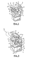
- la figure 6 à 9 sont des vues homologues des figures 1 à 4 montrant le collier de la figure 1 préparé pour la fixation d'un tuyau de grand diamètre ;
- la figure 10 est une vue homologue de celle de la figure 5 montrant le collier de la figure 6 en position fermée, et
- la figure 11 est une coupe, analogue à celle de la figure 9, montrant le collier en position fermée.
- Figure 1 is a perspective view of a collar according to the invention, ready to be used for fixing a small diameter pipe and in the open position;
- Figure 2 is a top view of the collar of Figure 1;
- Figure 3 is a left view of the collar of Figure 1;
- Figure 4 is a sectional view along the line IV-IV of the collar of Figures 2 and 3;
- Figure 5 shows the collar of Figure 1 in the closed position;
- Figures 6 to 9 are views similar to Figures 1 to 4 showing the collar of Figure 1 prepared for fixing a large diameter pipe;
- FIG. 10 is a view similar to that of FIG. 5 showing the collar of FIG. 6 in the closed position, and
- Figure 11 is a section similar to that of Figure 9 showing the collar in the closed position.
Sur les figures 1 et 5, on a représenté un collier selon l'invention destiné à la fixation de tuyaux de deux diamètres différents, l'un étant sensiblement le double de l'autre, le collier étant représenté dans son prépositionnement pour le petit diamètre et respectivement en position d'ouverture et en position de fermeture.In Figures 1 and 5, there is shown a collar according to the invention for fixing pipes of two different diameters, one being substantially double the other, the collar being shown in its prepositioning for small diameter and respectively in the open position and in the closed position.
Le collier comporte, à la manière connue, une base 1 permettant la fixation du collier sur une paroi notamment, à l'aide d'une vis ou d'un boulon engagé dans un trou 2 (figure 4) traversant la base 1, et deux segments de bride 3 et 4, disposés en face à face et montés articulés sur la base 1 par l'intermédiaire de charnières 5 agencées à l'extrémité de prolongements 6 de la base 1.The collar comprises, in the known manner, a
Les segments 3, 4, dénommés par la suite premiers segments, sont de forme arquée rectangulaire en présentant une face interne concave de courbure correspondant au diamètre externe du tuyau à fixer.The
Les charnières 5 relient les prolongements 6 aux premiers segments 3, 4 approximativement dans leur partie externe centrale.The
Toujours à la manière connue, les extrémités des premiers segments 3, 4 opposées à la base 1 sont munis de moyens d'accrochage mutuel lorsque le collier est en position de fermeture (figure 5), constitués d'une languette à crochet 7 sur l'un (4) des premiers segments et d'une saillie de verrouillage 8 sur l'autre segment (3).Still in the known manner, the ends of the
En 9 et 10 sont représentées deux nervures ménagées respectivement sur les premiers segments 3, 4 au voisinage des moyens d'accrochage 7, 8, pour permettre éventuellement la fermeture du collier sur un tuyau à l'aide d'une pince si nécessaire.In 9 and 10 are shown two ribs formed respectively on the
Conformément à l'invention, le collier décrit ci-dessus comporte en outre des moyens permettant, à l'aide du même collier, de fixer un tuyau présentant un diamètre externe inférieur à celui correspondant aux premiers segments de bride 3, 4, en l'occurrence un diamètre sensiblement égal à la moitié.According to the invention, the collar described above further comprises means making it possible, by means of the same collar, to fix a pipe having an external diameter less than that corresponding to the
A cet effet, chaque premier segment (3, 4) est muni d'un second segment de bride, respectivement 3' et 4', de courbure correspondant audit petit diamètre.For this purpose, each first segment (3, 4) is provided with a second flange segment, respectively 3 'and 4', of curvature corresponding to said small diameter.
Les seconds segments 3', 4' ont, comme les premiers segments 3, 4, une forme générale arquée rectangulaire et sont solidaires, par leur petit côté 11, 12 tourné vers la base, de l'extrémité 13, 14 des premiers segments 3, 4 proche de la base 1, cependant que le petit côté opposé, 15, 16 des segments 3', 4' est relié aux segments 3, 4 par un pontage 17, 18.The second segments 3 ', 4' have, like the
Les pontages 17, 18 présentent une forme également rectangulaire, plane et ont une épaisseur supérieure à celle des segments 3', 4' et sensiblement égale à celle des segments 3, 4.The
Les pontages 17, 18 sont reliés aux seconds segments 3', 4' par une partie d'épaisseur réduite formant charnière 19 et aux premiers segments 3, 4 par une partie d'épaisseur réduite formant charnière 20. les charnières 20 se trouvent sensiblement à une mi-distance entre les charnières 5 et les extrémités (7, 8) des premiers segments 3, 4.The
Par ailleurs, les zones des premiers segments 3, 4 situées entre les charnières 11 et 20, d'une part, et entre les charnières 12 et 20, d'autre part, sont ouvertes totalement en sorte de ménager une fenêtre arquée rectangulaire respectivement 21 et 22, vers laquelle les seconds segments 3', 4' avec leur pontage 17, 18 vont pouvoir être poussés à des fins d'escamotage, comme on le verra plus loin, grâce à l'élasticité du matériau constitutif du collier.Furthermore, the zones of the
Le collier est en effet avantageusement réalisé en une seule pièce par moulage d'une matière plastique appropriée, semi-rigide et permettant par une certaine élasticité aux diverses charnières (5, 11, 12, 19 et 20) de jouer leur rôle.The collar is indeed advantageously made in one piece by molding a suitable plastic material, semi-rigid and allowing a certain elasticity to the various hinges (5, 11, 12, 19 and 20) to play their role.
En position d'ouverture du collier, comme représenté sur les figures 1 à 4, les seconds segments 3', 4' avec leur pontage 17, 18, font saillie dans l'espace entre les premiers segments 3, 4.In the open position of the collar, as represented in FIGS. 1 to 4, the second segments 3 ', 4' with their
Les seconds segments 3', 4' sont ouverts, leurs bords inférieurs (côté base 1) étant parallèles et proches l'un de l'autre, cependant que leur bords supérieurs (15, 16) sont écartés d'une distance très sensiblement supérieure au diamètre externe du tuyau T1 (figure 4), de petit diamètre, à fixer sur le collier.The second segments 3 ', 4' are open, their lower edges (base side 1) being parallel and close to each other, while their upper edges (15, 16) are spaced apart by a much greater distance. to the outer diameter of the pipe T1 (Figure 4), small diameter, to be fixed on the collar.
Le tuyau T1 est déplacé manuellement suivant la flèche 23, entre les premiers segments 3, 4 puis les seconds segments 3', 4', en direction de la base 1, après fixation bien entendu du collier sur le support concerné.The pipe T1 is moved manually along the
Par pression du tuyau T1 sur les parties 13, 14 des premiers segments 3, 4, ces derniers, ainsi que les seconds segments 3', 4' qu'ils portent, basculent autour des charnières 5, en sorte qu'en fin de course du tuyau, les seconds segments 3', 4' se referment sur lui et, dans le même temps, les moyens 7, 8 se verrouillent mutuellement comme représenté sur la figure 5.By pressure of the pipe T1 on the
Le tuyau T1 est alors fermement enserré et tenu en place par l'effet d'arc-boutement procuré par les pontages 17, 18 plaquant les seconds segments 3', 4' contre le tuyau en prenant appui sur les premiers segments 3, 4.The pipe T1 is then firmly gripped and held in place by the bracing effect provided by the
Cette première position, en saillie dans l'espace entre segments 3, 4, des seconds segments 3', 4' est stable en ce sens que toute tentative pour écarter lesdits seconds segments est contrée par l'arc-boutement élastique des pontages 17, 18.This first position, protruding in the space between
Lorsque l'on veut utiliser le collier pour la fixation d'un tuyau T2 (figure 9) de grand diamètre, on escamote par pression manuelle les ensembles seconds segments 3', 4' - pontages 17, 18, comme illustré par les figures 6 et 9 , en poussant lesdits ensembles vers les ouvertures 21, 22. Pour ce faire, on doit vaincre l'opposition formée par les pontages 17, 18 jusqu'au moment sensiblement de l'alignement entre les points 11, 19, 20, d'une part et 12, 19, 20, d'autre part.When it is desired to use the collar for fixing a T2 pipe (FIG. 9) of large diameter, the second segment segments 3 ', 4' - by-
Une fois ce point d'alignement dépassé, et par effet de bascule élastique, lesdits ensembles 3', 17 et 4', 18 se positionnent élastiquement dans la seconde position stable, dite d'escamotage, illustrée par la figure 9. lesdits ensembles se trouvent sensiblement à hauteur des ouvertures 21, 22 et dégagent ainsi totalement l'espace entre les premiers segments 3, 4.Once this alignment point is exceeded, and by elastic rocking effect, said
Il est à noter que l'escamotage manuel préalable des ensembles 3', 4' ; 17, 18 n'est pas indispensable, car l'engagement du tuyau T2 à l'intérieur du collier va contraindre lesdits ensemble 3', 4' ; 17, 18 à s'écarter au passage dudit tuyau, du fait de l'élasticité du matériau du collier.It should be noted that the prior manual retraction of the sets 3 ', 4'; 17, 18 is not essential, because the engagement of the pipe T2 inside the collar will constrain said assembly 3 ', 4'; 17, 18 to deviate at the passage of said pipe, due to the elasticity of the collar material.
On a représenté sur la figure 11 en traits pleins la position d'escamotage des ensembles 3', 17 et 4', 18 et en tiretés la position dite "petit diamètre" desdits ensembles.FIG. 11 shows in solid lines the position of retraction of the
Le tuyau T2 est engagé dans le collier (figure 9) comme dans le mode d'utilisation de la figure 4, en direction (flèche 23) de la base 1, comme dans le cas d'un collier conventionnel présentant les seuls segments 3, 4.The pipe T2 is engaged in the collar (FIG. 9) as in the mode of use of FIG. 4, in the direction (arrow 23) of the
La fixation du tuyau T2 est également assurée, dans ce cas, à la manière connue.Fixing the T2 pipe is also ensured, in this case, in the known manner.
Si une partie des pontages 17, 18, se trouve en légère saillie à l'intérieur de l'espace entre les segments 3, 4, la fermeture complète de ces derniers autour du tuyau T2 entraînera le poussage par ce dernier desdites parties dans les ouvertures 21, 22 et ne gênera aucunement le serrage effectif et le verrouillage du tuyau.If a portion of the
Le rapport entre les diamètres des tuyaux T1, T2 peut bien entendu varier dans une large mesure, la courbure des segments 3', 4' et la longueur des pontages 17, 18 étant adaptées au diamètre du tuyau le plus petit des deux. Le collier de l'invention peut également naturellement accepter pour chacun des deux diamètres de légères variations, en plus ou en moins, du diamètre nominal, du fait de l'élasticité du matériau du collier.The ratio between the diameters of the pipes T1, T2 can of course vary to a large extent, the curvature of the segments 3 ', 4' and the length of the
Claims (5)
- Adaptable pipe clamp, comprising a fixing base (1), two first opposing collar segments (3, 4) articulated on said base by means of a hinge (5) connecting the base to a central external part of each segment, the ends of said segments opposite to said base being provided with mutual coupling means (7, 8), where said first segments (3, 4) are each provided with a second collar segment (3', 4'), with curvature more pronounced than that of the first segments, said second segments being disposed facing each other and connected at their ends to the first segments by hinges (11, 12, 19, 20) and being capable of occupying, as wished, one or other of two stable extreme positions, one, in which they protrude into the space between the first segments (3, 4), so as to constitute, upon closure of the first segments, a second collar with a diameter smaller than that of the collar formed by the first segments and the other, so-called retraction position, in which the second segments (3', 4') are capable of being pushed into an opening (21, 22) made in the first segments (3, 4).
- Clamp according to Claim 1, characterised in that the second collar segments (3', 4') have one end (11, 12) substantially common with the end (13, 14), on the base (1) side, of the first segments (3, 4), while the other end (15, 16) is connected by a deformable flexible bridge (17, 18) to the first segment (3, 4), close to the end of the first segment opposite to the base, each second segment (3', 4') - bridge (17, 18) assembly being capable, in said retraction position, of being pushed into said opening.
- Clamp according to Claim 2, characterised in that said second segments (3', 4'), said bridges (17, 18) and said openings (21, 22) are rectangular in shape and said bridges (17, 18) are connected at each end by a hinge of reduced thickness (19, 20) to said second segments (3', 4') and to said first segments (3, 4) respectively.
- Clamp according to one of Claims 1 to 3, characterised in that it is made in a single piece by moulding a suitable plastic material.
- Clamp according to one of Claims 1 to 4, characterised in that, in the retraction position, the second segments totally clear the space between the first segments (3, 4).
Applications Claiming Priority (2)
| Application Number | Priority Date | Filing Date | Title |
|---|---|---|---|
| FR0104093A FR2822919B1 (en) | 2001-03-27 | 2001-03-27 | ADAPTABLE PIPE FIXING COLLAR |
| FR0104093 | 2001-03-27 |
Publications (2)
| Publication Number | Publication Date |
|---|---|
| EP1245883A1 EP1245883A1 (en) | 2002-10-02 |
| EP1245883B1 true EP1245883B1 (en) | 2006-09-06 |
Family
ID=8861575
Family Applications (1)
| Application Number | Title | Priority Date | Filing Date |
|---|---|---|---|
| EP02362006A Expired - Lifetime EP1245883B1 (en) | 2001-03-27 | 2002-03-27 | Pipe clamp |
Country Status (6)
| Country | Link |
|---|---|
| EP (1) | EP1245883B1 (en) |
| AT (1) | ATE338905T1 (en) |
| DE (1) | DE60214460T2 (en) |
| ES (1) | ES2272655T3 (en) |
| FR (1) | FR2822919B1 (en) |
| PT (1) | PT1245883E (en) |
Families Citing this family (3)
| Publication number | Priority date | Publication date | Assignee | Title |
|---|---|---|---|---|
| FR2943756B3 (en) * | 2009-03-25 | 2011-02-25 | Sarl Francois Inglese | FASTENING NECK FOR CONDUITS AND PIPES FOR IMPLANTATION ON WALLS, PLINTHS AND THE LIKE |
| DE102013203098A1 (en) * | 2013-02-26 | 2014-08-28 | Mahle International Gmbh | fastening device |
| ES2801224B2 (en) * | 2019-06-27 | 2021-07-12 | Unex Aparellaje Electrico Sl | FASTENING DEVICE FOR FASTENING A TUBE TO A WALL |
Family Cites Families (6)
| Publication number | Priority date | Publication date | Assignee | Title |
|---|---|---|---|---|
| JPS5064874U (en) * | 1973-10-18 | 1975-06-12 | ||
| CH598528A5 (en) | 1976-03-15 | 1978-04-28 | Egli Fischer & Co | |
| FR2589977B3 (en) | 1985-11-13 | 1987-12-11 | Trw Carr France Sa | RETAINING ELEMENT FOR ATTACHING AT LEAST ONE PIPE OR CABLE |
| FR2594903B1 (en) * | 1986-02-25 | 1988-08-26 | Sonofam | IMPROVED AUTOMATIC CLOSING CLAMP |
| DE4123430C1 (en) | 1991-07-15 | 1992-06-17 | Trw United-Carr Gmbh & Co Kg, 6753 Enkenbach-Alsenborn, De | |
| IT1282223B1 (en) | 1995-12-22 | 1998-03-16 | Fischer Italia Sas Di Paolo Mo | MONOLITHIC PIPE CLAMP IN PLASTIC MATERIAL |
-
2001
- 2001-03-27 FR FR0104093A patent/FR2822919B1/en not_active Expired - Fee Related
-
2002
- 2002-03-27 PT PT02362006T patent/PT1245883E/en unknown
- 2002-03-27 EP EP02362006A patent/EP1245883B1/en not_active Expired - Lifetime
- 2002-03-27 ES ES02362006T patent/ES2272655T3/en not_active Expired - Lifetime
- 2002-03-27 AT AT02362006T patent/ATE338905T1/en not_active IP Right Cessation
- 2002-03-27 DE DE60214460T patent/DE60214460T2/en not_active Expired - Fee Related
Also Published As
| Publication number | Publication date |
|---|---|
| FR2822919B1 (en) | 2003-12-05 |
| DE60214460D1 (en) | 2006-10-19 |
| DE60214460T2 (en) | 2007-09-13 |
| EP1245883A1 (en) | 2002-10-02 |
| ATE338905T1 (en) | 2006-09-15 |
| PT1245883E (en) | 2007-01-31 |
| FR2822919A1 (en) | 2002-10-04 |
| ES2272655T3 (en) | 2007-05-01 |
Similar Documents
| Publication | Publication Date | Title |
|---|---|---|
| FR2613454A1 (en) | TUBULAR COUPLING FOR SOLIDARIZING TWO COAXIAL TUBES, OR FOR LOCKING A RESIDENTIAL TUBE | |
| EP0819391A1 (en) | Device for adjusting the length of a bracelet provided with a foldable fastener | |
| EP0571247B1 (en) | Quick-acting coupling for connecting a tubular element or an assembly of tubular elements to one or more openings | |
| EP1245883B1 (en) | Pipe clamp | |
| FR2762557A1 (en) | ARTICLE COMPRISING TWO ELEMENTS ARTICULATED ONE IN RELATION TO THE OTHER | |
| BE1008996A3 (en) | Joint flip cover for power outlet. | |
| FR2756670A1 (en) | CONNECTOR PROVIDED WITH A LOCKING LEVER | |
| WO1991011650A1 (en) | Device for locking two coaxial tubes | |
| FR2571465A1 (en) | COLLAR FOR PIPES | |
| FR2620176A1 (en) | TIGHTENING COLLAR WITH A RIBBON WITH SLOTTED LOOPS, FOR THE SUSPENSION OF A CLOSING SOLIDARIZATION SYSTEM | |
| FR2481897A1 (en) | Hair-grip comprising split annular clamp - with an integral hinge pref. made of polypropylene or nylon | |
| EP0879927B1 (en) | Car mounted plate tumbler cylinder lock comprising an improved sidebar | |
| FR2796674A1 (en) | Fastening for component such as plastic motor vehicle wing to support has retaining element with circular base and plate | |
| FR2627468A1 (en) | Hinged man hole cover - has hinged lid located in open slotted lugs with spring restraining clips to hold lid in open position | |
| EP1367213B1 (en) | Articulating ladder foot | |
| FR2798971A1 (en) | ARRANGEMENT FOR FIXING A BUILT-IN ELEMENT IN A LOCATION OPENING OF A SUPPORT PLATE | |
| EP1818459B1 (en) | Device for locking a frame with a bridging element that can be locked elastically on the frame | |
| FR2681025A1 (en) | WIPER BLADE COMPRISING LONGITUDINAL STOPPING MEANS OF THE WIPER BLADE. | |
| FR2732083A1 (en) | Simplified connector for joining metal sections for construction of exhibition stands | |
| CH702623A2 (en) | Lock Connector system for pipe lines in the event of expansion and / or contraction of the pipes. | |
| FR2539967A1 (en) | BELOVING LOOP OF A BELT OR THE LIKE | |
| FR2634043A1 (en) | Clip mainly for a display support frame | |
| FR2544411A1 (en) | One-piece fixing device with a retained nut | |
| FR2808570A1 (en) | BAYONET TYPE LOCKING CONNECTION ASSEMBLY | |
| EP0864763A1 (en) | Releasable connector in particular for a body element |
Legal Events
| Date | Code | Title | Description |
|---|---|---|---|
| PUAI | Public reference made under article 153(3) epc to a published international application that has entered the european phase |
Free format text: ORIGINAL CODE: 0009012 |
|
| AK | Designated contracting states |
Kind code of ref document: A1 Designated state(s): AT BE CH CY DE DK ES FI FR GB GR IE IT LI LU MC NL PT SE TR |
|
| AX | Request for extension of the european patent |
Free format text: AL;LT;LV;MK;RO;SI |
|
| 17P | Request for examination filed |
Effective date: 20030324 |
|
| AKX | Designation fees paid |
Designated state(s): AT BE CH CY DE DK ES FI FR GB GR IE IT LI LU MC NL PT SE TR |
|
| 17Q | First examination report despatched |
Effective date: 20041221 |
|
| GRAP | Despatch of communication of intention to grant a patent |
Free format text: ORIGINAL CODE: EPIDOSNIGR1 |
|
| GRAS | Grant fee paid |
Free format text: ORIGINAL CODE: EPIDOSNIGR3 |
|
| GRAA | (expected) grant |
Free format text: ORIGINAL CODE: 0009210 |
|
| AK | Designated contracting states |
Kind code of ref document: B1 Designated state(s): AT BE CH CY DE DK ES FI FR GB GR IE IT LI LU MC NL PT SE TR |
|
| PG25 | Lapsed in a contracting state [announced via postgrant information from national office to epo] |
Ref country code: IT Free format text: LAPSE BECAUSE OF FAILURE TO SUBMIT A TRANSLATION OF THE DESCRIPTION OR TO PAY THE FEE WITHIN THE PRESCRIBED TIME-LIMIT;WARNING: LAPSES OF ITALIAN PATENTS WITH EFFECTIVE DATE BEFORE 2007 MAY HAVE OCCURRED AT ANY TIME BEFORE 2007. THE CORRECT EFFECTIVE DATE MAY BE DIFFERENT FROM THE ONE RECORDED. Effective date: 20060906 Ref country code: IE Free format text: LAPSE BECAUSE OF FAILURE TO SUBMIT A TRANSLATION OF THE DESCRIPTION OR TO PAY THE FEE WITHIN THE PRESCRIBED TIME-LIMIT Effective date: 20060906 Ref country code: NL Free format text: LAPSE BECAUSE OF FAILURE TO SUBMIT A TRANSLATION OF THE DESCRIPTION OR TO PAY THE FEE WITHIN THE PRESCRIBED TIME-LIMIT Effective date: 20060906 Ref country code: FI Free format text: LAPSE BECAUSE OF FAILURE TO SUBMIT A TRANSLATION OF THE DESCRIPTION OR TO PAY THE FEE WITHIN THE PRESCRIBED TIME-LIMIT Effective date: 20060906 |
|
| REG | Reference to a national code |
Ref country code: GB Ref legal event code: FG4D Free format text: NOT ENGLISH |
|
| REG | Reference to a national code |
Ref country code: CH Ref legal event code: EP |
|
| REG | Reference to a national code |
Ref country code: IE Ref legal event code: FG4D Free format text: LANGUAGE OF EP DOCUMENT: FRENCH |
|
| REF | Corresponds to: |
Ref document number: 60214460 Country of ref document: DE Date of ref document: 20061019 Kind code of ref document: P |
|
| PG25 | Lapsed in a contracting state [announced via postgrant information from national office to epo] |
Ref country code: DK Free format text: LAPSE BECAUSE OF FAILURE TO SUBMIT A TRANSLATION OF THE DESCRIPTION OR TO PAY THE FEE WITHIN THE PRESCRIBED TIME-LIMIT Effective date: 20061206 Ref country code: SE Free format text: LAPSE BECAUSE OF FAILURE TO SUBMIT A TRANSLATION OF THE DESCRIPTION OR TO PAY THE FEE WITHIN THE PRESCRIBED TIME-LIMIT Effective date: 20061206 |
|
| REG | Reference to a national code |
Ref country code: CH Ref legal event code: NV Representative=s name: MICHELI & CIE INGENIEURS-CONSEILS |
|
| GBT | Gb: translation of ep patent filed (gb section 77(6)(a)/1977) |
Effective date: 20061214 |
|
| REG | Reference to a national code |
Ref country code: PT Ref legal event code: SC4A Free format text: AVAILABILITY OF NATIONAL TRANSLATION Effective date: 20061205 |
|
| NLV1 | Nl: lapsed or annulled due to failure to fulfill the requirements of art. 29p and 29m of the patents act | ||
| REG | Reference to a national code |
Ref country code: IE Ref legal event code: FD4D |
|
| PGFP | Annual fee paid to national office [announced via postgrant information from national office to epo] |
Ref country code: MC Payment date: 20070424 Year of fee payment: 7 |
|
| REG | Reference to a national code |
Ref country code: ES Ref legal event code: FG2A Ref document number: 2272655 Country of ref document: ES Kind code of ref document: T3 |
|
| PLBE | No opposition filed within time limit |
Free format text: ORIGINAL CODE: 0009261 |
|
| STAA | Information on the status of an ep patent application or granted ep patent |
Free format text: STATUS: NO OPPOSITION FILED WITHIN TIME LIMIT |
|
| 26N | No opposition filed |
Effective date: 20070607 |
|
| PG25 | Lapsed in a contracting state [announced via postgrant information from national office to epo] |
Ref country code: GR Free format text: LAPSE BECAUSE OF FAILURE TO SUBMIT A TRANSLATION OF THE DESCRIPTION OR TO PAY THE FEE WITHIN THE PRESCRIBED TIME-LIMIT Effective date: 20061207 |
|
| PGFP | Annual fee paid to national office [announced via postgrant information from national office to epo] |
Ref country code: CH Payment date: 20080910 Year of fee payment: 7 Ref country code: DE Payment date: 20080911 Year of fee payment: 7 Ref country code: ES Payment date: 20080924 Year of fee payment: 7 Ref country code: PT Payment date: 20080912 Year of fee payment: 7 |
|
| PGFP | Annual fee paid to national office [announced via postgrant information from national office to epo] |
Ref country code: AT Payment date: 20080924 Year of fee payment: 7 Ref country code: IT Payment date: 20080911 Year of fee payment: 7 |
|
| PGFP | Annual fee paid to national office [announced via postgrant information from national office to epo] |
Ref country code: GB Payment date: 20080910 Year of fee payment: 7 |
|
| PGFP | Annual fee paid to national office [announced via postgrant information from national office to epo] |
Ref country code: BE Payment date: 20080915 Year of fee payment: 7 |
|
| PG25 | Lapsed in a contracting state [announced via postgrant information from national office to epo] |
Ref country code: CY Free format text: LAPSE BECAUSE OF FAILURE TO SUBMIT A TRANSLATION OF THE DESCRIPTION OR TO PAY THE FEE WITHIN THE PRESCRIBED TIME-LIMIT Effective date: 20060906 Ref country code: LU Free format text: LAPSE BECAUSE OF NON-PAYMENT OF DUE FEES Effective date: 20070327 |
|
| BERE | Be: lapsed |
Owner name: LUCCHINA, PASCAL Effective date: 20090331 |
|
| REG | Reference to a national code |
Ref country code: PT Ref legal event code: MM4A Free format text: LAPSE DUE TO NON-PAYMENT OF FEES Effective date: 20090928 |
|
| PG25 | Lapsed in a contracting state [announced via postgrant information from national office to epo] |
Ref country code: PT Free format text: LAPSE BECAUSE OF NON-PAYMENT OF DUE FEES Effective date: 20090928 Ref country code: MC Free format text: LAPSE BECAUSE OF NON-PAYMENT OF DUE FEES Effective date: 20090331 Ref country code: AT Free format text: LAPSE BECAUSE OF NON-PAYMENT OF DUE FEES Effective date: 20090327 |
|
| REG | Reference to a national code |
Ref country code: CH Ref legal event code: PL |
|
| GBPC | Gb: european patent ceased through non-payment of renewal fee |
Effective date: 20090327 |
|
| PG25 | Lapsed in a contracting state [announced via postgrant information from national office to epo] |
Ref country code: CH Free format text: LAPSE BECAUSE OF NON-PAYMENT OF DUE FEES Effective date: 20090331 Ref country code: LI Free format text: LAPSE BECAUSE OF NON-PAYMENT OF DUE FEES Effective date: 20090331 Ref country code: DE Free format text: LAPSE BECAUSE OF NON-PAYMENT OF DUE FEES Effective date: 20091001 |
|
| PG25 | Lapsed in a contracting state [announced via postgrant information from national office to epo] |
Ref country code: BE Free format text: LAPSE BECAUSE OF NON-PAYMENT OF DUE FEES Effective date: 20090331 |
|
| PG25 | Lapsed in a contracting state [announced via postgrant information from national office to epo] |
Ref country code: GB Free format text: LAPSE BECAUSE OF NON-PAYMENT OF DUE FEES Effective date: 20090327 |
|
| PGFP | Annual fee paid to national office [announced via postgrant information from national office to epo] |
Ref country code: FR Payment date: 20091020 Year of fee payment: 8 |
|
| REG | Reference to a national code |
Ref country code: ES Ref legal event code: FD2A Effective date: 20090328 |
|
| PG25 | Lapsed in a contracting state [announced via postgrant information from national office to epo] |
Ref country code: ES Free format text: LAPSE BECAUSE OF NON-PAYMENT OF DUE FEES Effective date: 20090328 |
|
| REG | Reference to a national code |
Ref country code: FR Ref legal event code: ST Effective date: 20101130 |
|
| PG25 | Lapsed in a contracting state [announced via postgrant information from national office to epo] |
Ref country code: FR Free format text: LAPSE BECAUSE OF NON-PAYMENT OF DUE FEES Effective date: 20100331 |
|
| PG25 | Lapsed in a contracting state [announced via postgrant information from national office to epo] |
Ref country code: IT Free format text: LAPSE BECAUSE OF NON-PAYMENT OF DUE FEES Effective date: 20090327 |
|
| PG25 | Lapsed in a contracting state [announced via postgrant information from national office to epo] |
Ref country code: TR Free format text: LAPSE BECAUSE OF NON-PAYMENT OF DUE FEES Effective date: 20100922 |
|
| PGFP | Annual fee paid to national office [announced via postgrant information from national office to epo] |
Ref country code: TR Payment date: 20080916 Year of fee payment: 7 |
|
| PG25 | Lapsed in a contracting state [announced via postgrant information from national office to epo] |
Ref country code: TR Free format text: LAPSE BECAUSE OF NON-PAYMENT OF DUE FEES Effective date: 20090327 |