EP1245518A2 - Pile former - Google Patents
Pile former Download PDFInfo
- Publication number
- EP1245518A2 EP1245518A2 EP02006837A EP02006837A EP1245518A2 EP 1245518 A2 EP1245518 A2 EP 1245518A2 EP 02006837 A EP02006837 A EP 02006837A EP 02006837 A EP02006837 A EP 02006837A EP 1245518 A2 EP1245518 A2 EP 1245518A2
- Authority
- EP
- European Patent Office
- Prior art keywords
- stacking section
- rake
- conveying direction
- former according
- bar former
- Prior art date
- Legal status (The legal status is an assumption and is not a legal conclusion. Google has not performed a legal analysis and makes no representation as to the accuracy of the status listed.)
- Granted
Links
Images

Classifications
-
- B—PERFORMING OPERATIONS; TRANSPORTING
- B65—CONVEYING; PACKING; STORING; HANDLING THIN OR FILAMENTARY MATERIAL
- B65H—HANDLING THIN OR FILAMENTARY MATERIAL, e.g. SHEETS, WEBS, CABLES
- B65H29/00—Delivering or advancing articles from machines; Advancing articles to or into piles
- B65H29/66—Advancing articles in overlapping streams
-
- B—PERFORMING OPERATIONS; TRANSPORTING
- B65—CONVEYING; PACKING; STORING; HANDLING THIN OR FILAMENTARY MATERIAL
- B65H—HANDLING THIN OR FILAMENTARY MATERIAL, e.g. SHEETS, WEBS, CABLES
- B65H31/00—Pile receivers
- B65H31/32—Auxiliary devices for receiving articles during removal of a completed pile
-
- B—PERFORMING OPERATIONS; TRANSPORTING
- B65—CONVEYING; PACKING; STORING; HANDLING THIN OR FILAMENTARY MATERIAL
- B65H—HANDLING THIN OR FILAMENTARY MATERIAL, e.g. SHEETS, WEBS, CABLES
- B65H33/00—Forming counted batches in delivery pile or stream of articles
- B65H33/12—Forming counted batches in delivery pile or stream of articles by creating gaps in the stream
-
- B—PERFORMING OPERATIONS; TRANSPORTING
- B65—CONVEYING; PACKING; STORING; HANDLING THIN OR FILAMENTARY MATERIAL
- B65H—HANDLING THIN OR FILAMENTARY MATERIAL, e.g. SHEETS, WEBS, CABLES
- B65H2301/00—Handling processes for sheets or webs
- B65H2301/30—Orientation, displacement, position of the handled material
- B65H2301/32—Orientation of handled material
- B65H2301/324—Inclined
-
- B—PERFORMING OPERATIONS; TRANSPORTING
- B65—CONVEYING; PACKING; STORING; HANDLING THIN OR FILAMENTARY MATERIAL
- B65H—HANDLING THIN OR FILAMENTARY MATERIAL, e.g. SHEETS, WEBS, CABLES
- B65H2405/00—Parts for holding the handled material
- B65H2405/30—Other features of supports for sheets
- B65H2405/32—Supports for sheets partially insertable - extractable, e.g. upon sliding movement, drawer
- B65H2405/323—Cantilever finger member, e.g. reciprocating in parallel to plane of handled material
Definitions
- the present invention relates to a vertical bar former for Forming vertical stacks, so-called bars, from printed products, which are delivered in a stream of shed.
- Such known bar formers have a product feed Feed the scale flow in a conveying direction and a straight line Stack distance on.
- the stacking section follows the product feed and has an upper start and a lower end. Furthermore, in the area of the stacking section for the continuous formation of Rods several handling elements are provided.
- top of the stacking section is opposite to the lower beginning inclined in the conveying direction so that the in the area of the stacked printed products with their leading edge (Fold) automatically by gravity against one in the area of the stacking line the intended stop.
- This allows you to perform of the printed products through the product feed and when holding them down the product back less forces are applied, whereby smearing of the printed products by hold-down elements or pressure belt is avoided.
- the handling elements at least one displaceable along the stacking path and have rakes retractable into the stacking section, the upper one End position above the scale flow supplied by the product guide is arranged.
- the upper end position i.e. the waiting position the rake is thus above the shingled stream supplied, so that the rake touches the bar from above. This will Rod end held securely so that it cannot slip.
- the handling elements at least one displaceable along the stacking route Lowering fork, in the displacement of which a first feed for end plates is arranged.
- the lowering fork is used in a known manner, the Lower the bar during the bar forming process.
- This first feed for end plates is thus arranged in an area seen both in terms of space and in terms of time is not critical.
- the handling elements one slidable along the stacking path and into the Stackable retractable holding rake, in the displacement of which one second feed for end plates is arranged.
- a second end plate for example an upper end plate, after which the holding rake is placed from above this has been moved along the stacking route.
- the handling elements one slidable along the stacking path and into the Stackable retractable separating rake, the tines with a support tape are provided when the rake is withdrawn from the stacking section via a roller provided at the tip of the tine can be unrolled.
- a separating rake with a rollable Support tape or trigger tape can be prevented from a relative movement between the rake and the product stack above it takes place by the overlay during the retraction of the rake is rolled over the roll. This prevents the to transferring printed products are damaged or smeared.
- the product feed has at least three in the conveying direction and transverse to the conveying direction spaced pressure belts. With such pressure belts the shingled stream of printed products supplied can be accelerated and pre-pressed into the stacking section, at the same time proper orientation of each individual printed product is ensured.
- the product feed can be designed so that the position of the two outer pressure belts is adjustable transversely to the conveying direction. This makes it easy to adjust guaranteed because the middle pressure belt even with different Formats can maintain its location, while only the two outer pressure belts must be adjusted.
- An adjustability the outermost pressure belt has the additional advantage that each printed product of the shingled stream supplied is always at the top and is held and pressed when it is inserted into the stacking section becomes.
- a total of six pressure belts in the product feed are preferred provided, the two innermost pressure belts transverse to the conveying direction are not adjustable, and being the relative length of the two outermost Pressure belt and the relative position of the neighboring one Pressure belt is adjustable across the conveying direction.
- Such Product feeding can also be done with multi-pronged rakes at different Format sizes are used because of the adjustability of the Pressure belts easily adapt to different Formats is possible.
- the Product feed and the handling elements on a common Base attached is adjustable.
- a displacement device be provided, which is a fully formed rod from the Area of the stacking section guided on all sides to a pressing and strapping unit passes. This results in a fully automatic mode of operation the machine, while ensuring that the fully formed Also at the handover to the pressing and strapping unit is guided on all sides.
- Fig. 1 shows a side view of a vertical bar former for forming from bars S from printed products delivered in a shingled stream P.
- the bar former has a base frame 10
- Product feed 12 for feeding the scale flow P in one Direction of conveyance F, with a straight line on the product feed 12
- Stacking path 14 with an upper start in the area of the product feed P and a lower end connects.
- multiple handling elements are provided to continuously individual rods S from the delivered scale stream P. form.
- it is a separating rake 16, one Holding rake 18 and a lowering fork 20, each along the stacking path 14 are slidably attached to the base frame 10.
- the Lowering fork 20 slidable along a guide 22, whereas the Separating rake 16 and the holding rake 18 can be moved along a guide 24 are. Both guides overlap along the stacking route 14th
- Both the separating rake 16 and the holding rake 18 are in the stacking section 14 retractable (see illustration in Fig. 1) and can with the help of actuating cylinders 26 to the rear from the area of the stack section 14 be brought out.
- the stack path 14 is inclined, in such a way that the upper beginning of the stack section 14 with respect to the vertical in the conveying direction F (and not against the conveying direction). hereby includes a stop provided on the back of the conveyor line 14 28 with the horizontal an acute angle ⁇ , for example is about 70 °, and that opens in the conveying direction.
- a first feed 34 for end plates 36 is provided.
- a second feed 30 for end plates 32 is provided.
- a stacking plate can be fed through the feeds 30 and 34 32 or 36 are introduced into the stack section 14, the Lowering fork 20 takes over an end plate 36 from the feed 34 and the holding rake 18 takes over an end plate 32 from the guide 30, which is explained in more detail below.
- the displacement device 40 has a plurality of pivotable holding brackets 42, which are provided with pins 44, which when folded Press brackets 42 onto the top of the upper end plate 32. Above the bracket 42, a lateral guide 46 for the rod S may be provided.
- the product feeder 12 has a plurality of upper and lower pressure belts 50, 52 on, between them the shingled stream P from Lead printed products while pressing.
- the upper pressure belts 50 are longer than the lower pressure belts 52 and the front end of the upper pressure belt 50, 52 extends into the upper end of the stacking section 14.
- In this area 28 are parallel on the side of the stop and essentially in alignment with this a plurality of trigger belts 54 provided with the help of the product spine (fold) in the stacking line 14 imported printed products is pulled down.
- the upper end position of the separating rake 16 lies and the holding rake 18 above that through the product guide 12 fed scale stream P when its products in the stacking section 14 occur. This means that the rakes 16, 18 during a lowering movement dive through the stream of scale. Because the top Pressure belt 50 of the product feed 12 into the area of the stacking section are introduced (see FIG. 1), the rakes 16, 18 must comb the top pressure belt 50.
- Fig. 2 shows a top view this arrangement in detail.
- Fig. 2 is a plan view of the separating rake 16 is shown with combs the pressure belt 50a-50f of the product feed 12. simultaneously can be seen that the tines of the separating rake 16 by in the Stop 28 provided slots are passed and that the Separating rake 16 with the help of the actuating cylinder 26 in the direction of the double arrow 27 into and out of the stack section 14.
- the separating rake 16 has five in the illustrated embodiment Tines on, one tine between two adjacent pressure belts 50a, 50b, 50c, 50d and 50e, 50f comes to rest. When lowering of the separating rake 16 along the guide 24 would come the tines Computing 16 with the pressure belt of the product feed 12, so that the Rake 16 can pass through the product feed 12.
- the separating rake 18 is designed in the same way as the separating rake 16 and is from the position shown in Fig. 1 together with the separating rake 16 lowered, with the start of the lowering movement both rakes are directly one above the other.
- the separating rake 16 and the holding rake 18 shoot together in the Stack distance 14 after a separator 60 a certain Gap in the shingled stream created and after that gap up has reached the area of the stack section 14. Then be this lowered at the same time so that it with the pressure belt 50a - 50f comb the product feeder 12.
- the holding rake 18 is then moved at the same speed as the lowering fork 20, so that the fully formed rod between the lowering fork 20 and the Holding rake 18 is clamped.
- the separating rake 16 is used with the usual Rod formation speed lowered, so that on this one forms new partial stack.
- the bar builder a format adjustment that acts in the conveying direction F and a format adjustment that is transverse to the conveying direction F of the conveyed Products P works.
- the product feed in the illustrated Embodiment six upper pressure belts 50a - 50f on the a base 70 are attached. All pressure belts run parallel and each take a prong of rakes 16 and 18 between them. As indicated in Fig. 2 by double arrows, the two can outermost pressure belts 50a and 50f transverse to the product conveying direction F can be adjusted (arrows A, B), with an additional relative adjustment between the two outermost pressure belts 50a and 50b or 50e and 50f is possible (arrows C, D). This ensures that each product on both of them lying transversely to the conveying direction extreme edges of pressure belts (pressure belts 50a and 50f) is held and that the remaining pressure belts evenly over the Area of the product are distributed.
- Base 70 can be reached along the double arrow 72.
- the guide 24 of the rake 16, 18 and the guide 22 of the lowering fork 20 is connected by simply moving the base 70 along the double arrow 72 an adjustment of all required settings causes.
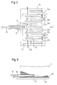
- FIG. 3 shows an alternative embodiment of a holding rake 18 ' the transfer of a formed partial stack S to the lowering fork 20 or the end plate 36 located on this.
- a deflection roller at the ends of each prong of the separating rake 18 ' 82 is provided, with a support belt around each deflection roller 82 80 is performed.
- the rake 18 ' is pulled back, the upper run of the support tape 80 at the left end (in Fig. 3), so that when withdrawing the rake 18 'simultaneously with the lower run of the Support tape 80 this can roll around the pulley 82.
- the partial stack S located on the support belt 80 is unrolled without that a relative movement between the rake 18 'and the sub-stack S takes place. In this way, an extremely gentle transfer of the Partial stack formed.
- the separation device 60 to introduce a gap in the shingled stream in provided such a height above the ground that it can move from one to the other the operator standing on the floor can be easily reached.
Landscapes
- Engineering & Computer Science (AREA)
- Mechanical Engineering (AREA)
- Feeding Of Articles By Means Other Than Belts Or Rollers (AREA)
- Forming Counted Batches (AREA)
- Pile Receivers (AREA)
- Superconductors And Manufacturing Methods Therefor (AREA)
- Holo Graphy (AREA)
- Grinding Of Cylindrical And Plane Surfaces (AREA)
- Radiation-Therapy Devices (AREA)
Abstract
Description
Die vorliegende Erfindung betrifft einen vertikalen Stangenbildner zum Bilden von vertikalen Stapeln, sogenannten Stangen, aus Druckprodukten, die in einem Schuppenstrom angeliefert werden.The present invention relates to a vertical bar former for Forming vertical stacks, so-called bars, from printed products, which are delivered in a stream of shed.
Derartige bekannte Stangenbildner weisen eine Produktzuführung zum Zuführen des Schuppenstromes in einer Förderrichtung und eine geradlinige Stapelstrecke auf. Die Stapelstrecke schließt sich an die Produktzuführung an und weist einen oberen Anfang und ein unteres Ende auf. Ferner sind im Bereich der Stapelstrecke zur kontinuierlichen Bildung von Stangen mehrere Handhabungselemente vorgesehen.Such known bar formers have a product feed Feed the scale flow in a conveying direction and a straight line Stack distance on. The stacking section follows the product feed and has an upper start and a lower end. Furthermore, in the area of the stacking section for the continuous formation of Rods several handling elements are provided.
Es ist die Aufgabe der vorliegenden Erfindung, einen Stangenbildner nach dem Oberbegriff des Anspruchs 1 dahingehend zu verbessern, daß bei hoher Leistung die zu einer Stange gestapelten Druckprodukte weniger beschädigt werden.It is the object of the present invention to create a bar former to improve the preamble of claim 1 in that high performance less the stacked printed products to be damaged.
Die Lösung dieser Aufgabe erfolgt durch die Merkmale des Anspruchs 1 und insbesondere dadurch, daß der obere Anfang der Stapelstrecke gegenüber der Vertikalen in Förderrichtung geneigt ist.This object is achieved by the features of claim 1 and in particular in that the top of the stack section opposite the vertical is inclined in the conveying direction.
Erfindungsgemäß wird der obere Anfang der Stapelstrecke gegenüber dem unteren Anfang geneigt und zwar in Förderrichtung, so daß die im Bereich der Stapelstrecke abgelegten Druckprodukte mit ihrer vorlaufenden Kante (Falz) von selbst mittels Schwerkraft gegen einen im Bereich der Stapelstrecke vorgesehenen Anschlag rutschen. Hierdurch können beim Durchführen der Druckprodukte durch die Produktzuführung sowie beim Niederhalten der Produktrücken geringere Kräfte aufgebracht werden, wodurch ein Verschmieren der Druckprodukte durch Niederhalteelemente oder Andruckriemen vermieden ist. Gleichzeitig ergibt-sich insgesamt eine verbesserte Stangenbildung, da sich die Produkte von selbst ausrichten.According to the top of the stacking section is opposite to the lower beginning inclined in the conveying direction so that the in the area of the stacked printed products with their leading edge (Fold) automatically by gravity against one in the area of the stacking line the intended stop. This allows you to perform of the printed products through the product feed and when holding them down the product back less forces are applied, whereby smearing of the printed products by hold-down elements or pressure belt is avoided. At the same time, there is a total Improved bar formation as the products align themselves.
Vorteilhafte Ausführungsformen der Erfindung sind in der Beschreibung, den Ansprüchen sowie den Zeichnungen beschrieben.Advantageous embodiments of the invention are in the description, the claims and the drawings described.
Nach einer ersten vorteilhaften Ausführungsform können die Handhabungselemente zumindest einen entlang der Stapelstrecke verschiebbaren und in die Stapelstrecke einfahrbaren Rechen aufweisen, dessen obere Endposition oberhalb des durch die Produktführung zugeführten Schuppenstromes angeordnet ist. Die obere Endposition, d.h. die Warteposition des Rechens liegt somit oberhalb des zugeführten Schuppenstromes, so daß der Rechen von oben auf die Stange aufsetzt. Hierdurch wird das Stangenende sicher gehalten, so daß es nicht verrutschen kann.According to a first advantageous embodiment, the handling elements at least one displaceable along the stacking path and have rakes retractable into the stacking section, the upper one End position above the scale flow supplied by the product guide is arranged. The upper end position, i.e. the waiting position the rake is thus above the shingled stream supplied, so that the rake touches the bar from above. This will Rod end held securely so that it cannot slip.
Nach einer weiteren vorteilhaften Ausführungsform weisen die Handhabungselemente zumindest eine entlang der Stapelstrecke verschiebbare Senkgabel auf, in deren Verschiebeweg eine erste Zuführung für Endplatten angeordnet ist. Die Senkgabel dient auf bekannte Weise dazu, die Stange während des Stangenbildungsprozesses abzusenken. Erfindungsgemäß besteht beim Zurückfahren der Senkgabel die Möglichkeit, eine Endplatte für die nächste zu bildende Stange zu übernehmen, da im Verschiebeweg der Senkgabel eine Endplattenzuführung vorgesehen ist. According to a further advantageous embodiment, the handling elements at least one displaceable along the stacking route Lowering fork, in the displacement of which a first feed for end plates is arranged. The lowering fork is used in a known manner, the Lower the bar during the bar forming process. According to the invention there is the possibility of retracting the lowering fork End plate for the next rod to be formed, because in the Displacement of the lowering fork is provided an end plate feed.
Diese erste Zuführung für Endplatten ist somit in einem Bereich angeordnet, der sowohl räumlich wie auch von der zeitlichen Abfolge her gesehen unkritisch ist.This first feed for end plates is thus arranged in an area seen both in terms of space and in terms of time is not critical.
Nach einer weiteren vorteilhaften Ausführungsform weisen die Handhabungselemente einen entlang der Stapelstrecke verschiebbaren und in die Stapelstrecke einfahrbaren Halterechen auf, in dessen Verschiebeweg eine zweite Zuführung für Endplatten angeordnet ist. Auch hier besteht erfindungsgemäß die Möglichkeit, daß eine zweite Endplatte, beispielsweise eine obere Endplatte, auf den Halterechen von oben aufgelegt wird, nachdem dieser entlang der Stapelstrecke verfahren worden ist.According to a further advantageous embodiment, the handling elements one slidable along the stacking path and into the Stackable retractable holding rake, in the displacement of which one second feed for end plates is arranged. Here too, according to the invention the possibility that a second end plate, for example an upper end plate, after which the holding rake is placed from above this has been moved along the stacking route.
Nach einer weiteren Ausführungsform der Erfindung können die Handhabungselemente einen entlang der Stapelstrecke verschiebbaren und in die Stapelstrecke einfahrbaren Trennrechen aufweisen, dessen Zinken mit einem Auflageband versehen sind, das beim Zurückziehen des Rechens aus der Stapelstrecke über eine an der Spitze der Zinke vorgesehene Rolle abrollbar ist. Durch einen solchen Trennrechen mit einem abrollbaren Auflageband oder Abzugsband läßt sich verhindern, daß eine Relativbewegung zwischen dem Rechen und dem darüber befindlichen Produktstapel stattfindet, indem das Auflageband während des Zurückziehens des Rechens über die Rolle abgerollt wird. Hierdurch wird verhindert, daß die zu übergebenden Druckprodukte beschädigt oder verschmiert werden.According to a further embodiment of the invention, the handling elements one slidable along the stacking path and into the Stackable retractable separating rake, the tines with a support tape are provided when the rake is withdrawn from the stacking section via a roller provided at the tip of the tine can be unrolled. By such a separating rake with a rollable Support tape or trigger tape can be prevented from a relative movement between the rake and the product stack above it takes place by the overlay during the retraction of the rake is rolled over the roll. This prevents the to transferring printed products are damaged or smeared.
Nach einer weiteren Ausbildung der Erfindung weist die Produktzuführung mindestens drei in Förderrichtung verlaufende und quer zur Förderrichtung beabstandete Andruckriemen auf. Durch derartige Andruckriemen läßt sich der zugeführte Schuppenstrom von Druckprodukten beschleunigt und vorgepreßt in die Stapelstrecke einbringen, wobei gleichzeitig eine ordnungsgemäße Orientierung jedes einzelnen Druckproduktes sichergestellt ist.According to a further embodiment of the invention, the product feed has at least three in the conveying direction and transverse to the conveying direction spaced pressure belts. With such pressure belts the shingled stream of printed products supplied can be accelerated and pre-pressed into the stacking section, at the same time proper orientation of each individual printed product is ensured.
Nach einer weiteren Ausbildung der Erfindung kann die Produktzuführung so ausgebildet sein, daß die Lage der beiden äußeren Andruckriemen quer zur Förderrichtung einstellbar ist. Hierdurch ist eine einfache Einstellbarkeit gewährleistet, da der mittlere Andruckriemen auch bei unterschiedlichen Formaten seine Lage beibehalten kann, während lediglich die beiden äußeren Andruckriemen eingestellt werden müssen. Eine Verstellbarkeit der jeweils äußersten Andruckriemen hat zusätzlich den Vorteil, daß jedes Druckprodukt des zugeführten Schuppenstromes stets an Kopf und Fuß gehalten und gepreßt ist, wenn dieses in die Stapelstrecke eingeführt wird.According to a further embodiment of the invention, the product feed can be designed so that the position of the two outer pressure belts is adjustable transversely to the conveying direction. This makes it easy to adjust guaranteed because the middle pressure belt even with different Formats can maintain its location, while only the two outer pressure belts must be adjusted. An adjustability the outermost pressure belt has the additional advantage that each printed product of the shingled stream supplied is always at the top and is held and pressed when it is inserted into the stacking section becomes.
Bevorzugt sind insgesamt sechs Andruckriemen in der Produktzuführung vorgesehen, wobei die zwei innersten Andruckriemen quer zur Förderrichtung nicht verstellbar sind, und wobei die relative Läge der beiden äußersten Andruckriemen sowie die relative Lage des dazu jeweils benachbarten Andruckriemens quer zur Förderrichtung einstellbar ist. Eine solche Produktzuführung kann auch mit vielzinkigen Rechen bei unterschiedlichen Formatgrößen eingesetzt werden, da durch die Einstellbarkeit der Andruckriemen auf einfache Weise eine Anpassung an unterschiedliche Formate möglich ist. Gleichzeitig ist wieder sichergestellt, daß die Produkte stets an ihren beiden äußersten gegenüberliegenden Rändern, d.h. an Kopf und Fuß, sicher gepreßt und gehalten sind. Gleichzeitig ergibt sich eine besonders einfache Einstellung der Andruckriemen. A total of six pressure belts in the product feed are preferred provided, the two innermost pressure belts transverse to the conveying direction are not adjustable, and being the relative length of the two outermost Pressure belt and the relative position of the neighboring one Pressure belt is adjustable across the conveying direction. Such Product feeding can also be done with multi-pronged rakes at different Format sizes are used because of the adjustability of the Pressure belts easily adapt to different Formats is possible. At the same time, it is again ensured that the products always at their two outermost opposite edges, i.e. on Head and foot, securely pressed and held. At the same time it results a particularly easy adjustment of the pressure belt.
Nach einer weiteren vorteilhaften Ausführungsform der Erfindung sind die Produktzuführung und die Handhabungselemente auf einer gemeinsamen Basis befestigt, wobei der Abstand zwischen Basis und Stapelstrecke in Förderrichtung verstellbar ist. Hierdurch kann eine Formatanpassung auch in Förderrichtung, d.h. in Breitenrichtung der Druckprodukte erfolgen, wobei wiederum eine besonders einfache Verstellbarkeit gewährleistet ist, da lediglich die Basis in Förderrichtung auf die Produktbreite eingestellt werden muß.According to a further advantageous embodiment of the invention, the Product feed and the handling elements on a common Base attached, the distance between the base and the stacking distance in The direction of conveyance is adjustable. This allows a format adjustment also in the direction of conveyance, i.e. in the width direction of the printed products, again ensuring particularly easy adjustability is because only the base in the conveying direction is set to the product width must become.
Nach einer weiteren vorteilhaften Ausführungsform ist eine Einheit zum Einbringen einer Lücke in den Schuppenstrom vorgesehen, die in einer solchen Höhe über dem Boden angeordnet ist, daß sie von einer auf dem Boden stehenden Bedienperson bequem erreicht werden kann, wobei eine Transporteinrichtung zum Weitertransport des Produktstromes zu der an dem oberen Ende der Stapelstrecke vorgesehenen Produktzuführung vorgesehen ist. Eine solche Ausführungsform bringt einen erheblichen Bedienvorteil mit sich, da die Einstellung der Einheit zum Einbringen einer Lücke in den Schuppenstrom von dem Bediener bequem vorgenommen werden kann, ohne daß dieser auf einer Leiter, einem Podest oder dergleichen stehen muß.According to a further advantageous embodiment, a unit for Introducing a gap in the shingled stream provided in a such a height above the ground that it is from one on the Floor operator can be easily reached, one Transport device for further transport of the product stream to the the product feed provided at the upper end of the stacking section is provided. Such an embodiment brings considerable Operating advantage with it, since the setting of the unit for insertion a gap in the shingled stream conveniently made by the operator can be without it on a ladder, a pedestal or the like must stand.
Nach einer weiteren vorteilhaften Ausführungsform kann eine Verschiebeeinrichtung vorgesehen sein, die eine vollständig gebildete Stange aus dem Bereich der Stapelstrecke allseitig geführt an eine Preß- und Umreifungseinheit übergibt. Hierdurch ergibt sich eine vollautomatische Arbeitsweise der Maschine, wobei dennoch sichergestellt ist, daß die vollständig gebildete Stange auch bei der Übergabe an die Preß- und Umreifungseinheit an allen Seiten geführt ist. According to a further advantageous embodiment, a displacement device be provided, which is a fully formed rod from the Area of the stacking section guided on all sides to a pressing and strapping unit passes. This results in a fully automatic mode of operation the machine, while ensuring that the fully formed Also at the handover to the pressing and strapping unit is guided on all sides.
Nachfolgend wird die vorliegende Erfindung rein beispielhaft anhand vorteilhafter Ausführungsformen und unter Bezugnahme auf die beigefügten Zeichnungen beschreiben. Es zeigen:
- Fig. 1
- eine stark vereinfachte schematische Seitenansicht eines vertikalen Stangenbildners;
- Fig. 2
- eine stark vereinfachte Draufsicht auf die Produktzuführung mit eingeführtem Rechen; und
- Fig. 3
- eine vereinfachte Seitenansicht eines mit einem Auflageband versehenen Rechens bei der Übergabe eines Produktstapels.
- Fig. 1
- a greatly simplified schematic side view of a vertical bar former;
- Fig. 2
- a greatly simplified top view of the product feed with an inserted rake; and
- Fig. 3
- a simplified side view of a rake provided with a support belt when transferring a product stack.
Fig. 1 zeigt eine Seitenansicht eines vertikalen Stangenbildners zum Bilden
von Stangen S aus in einem Schuppenstrom P angelieferten Druckprodukten.
Der Stangenbildner weist auf einem Grundgestell 10 eine
Produktzuführung 12 zum Zuführen des Schuppenstromes P in einer
Förderrichtung F auf, wobei sich an die Produktzuführung 12 eine geradlinige
Stapelstrecke 14 mit einem oberen Anfang im Bereich der Produktzuführung
P und einem unteren Ende anschließt. Im Bereich der Stapelstecke
14 sind mehrere Handhabungselemente vorgesehen, um kontinuierlich
einzelne Stangen S aus dem angeförderten Schuppenstrom P zu
bilden. Im einzelnen handelt es sich um einen Trennrechen 16, einen
Halterechen 18 und eine Senkgabel 20, die jeweils entlang der Stapelstrecke
14 verschiebbar an dem Grundgestell 10 befestigt sind. Hierbei ist die
Senkgabel 20 entlang einer Führung 22 verschiebbar, wohingegen der
Trennrechen 16 und der Halterechen 18 entlang einer Führung 24 verschiebbar
sind. Beide Führungen überlappen sich entlang der Stapelstrecke
14.Fig. 1 shows a side view of a vertical bar former for forming
from bars S from printed products delivered in a shingled stream P.
The bar former has a
Sowohl der Trennrechen 16 wie auch der Halterechen 18 sind in die Stapelstrecke
14 einfahrbar (vgl. Darstellung in Fig. 1) und können mit Hilfe
von Stellzylindern 26 nach hinten aus dem Bereich der Stapelstrecke 14
herausgefahren werden.Both the separating
Wie Fig. 1 zeigt, ist die Stapelstrecke 14 geneigt, und zwar derart, daß der
obere Anfang der Stapelstrecke 14 gegenüber der Vertikalen in Förderrichtung
F (und nicht entgegen der Förderrichtung) geneigt ist. Hierdurch
schließt ein an der Rückseite der Förderstrecke 14 vorgesehener Anschlag
28 mit der Horizontalen einen spitzen Winkel α ein, der beispielsweise
etwa 70° beträgt, und der sich in Förderrichtung öffnet.1 shows, the
Etwa im mittleren Drittel der Stapelstrecke 14 ist parallel zu den Rechen
16, 18 eine erste Zuführung 34 für Endplatten 36 vorgesehen. Im oberen
Drittel der Stapelstrecke ist rechtwinklig zu dem Anschlag 28 und parallel
zu der ersten Zuführung 34 eine zweite Zuführung 30 für Endplatten 32
vorgesehen. Durch die Zuführungen 30 und 34 kann jeweils eine Stapelplatte
32 bzw. 36 in die Stapelstrecke 14 eingebracht werden, wobei die
Senkgabel 20 eine Endplatte 36 von der Zuführung 34 übernimmt und
der Halterechen 18 eine Endplatte 32 von der Führung 30 übernimmt,
was nachfolgend noch näher erläutert wird.Approximately in the middle third of the
Wie Fig. 1 ferner zeigt, ist im unteren Bereich der Stapelstrecke 14 eine
Verschiebeeinrichtung 40 angeordnet. Mit dieser Verschiebeeinrichtung
kann die vollständig gebildete Stange S aus dem Bereich der Stapelstrecke
14 an eine (nicht dargestellte) Preß- und Umreifungseinheit übergeben
werden. Hierzu wird die Stange S in einer Richtung senkrecht zur Zeichenebene
verschoben. Anschließend wird die Stange gepreßt und umreift.As further shown in FIG. 1, there is one in the lower region of the
Um während des Transfers eine allseitige Führung der Stange S zu erhalten,
weist die Verschiebeeinrichtung 40 mehrere verschwenkbare Haltewinkel
42 auf, die mit Zapfen 44 versehen sind, welche bei eingeklappten
Haltewinkeln 42 auf die Oberseite der oberen Endplatte 32 drücken.
Oberhalb der Haltewinkel 42 kann eine seitliche Führung 46 für die Stange
S vorgesehen sein.In order to obtain all-round guidance of the rod S during the transfer,
the
Die Produktzuführung 12 weist mehrere obere und untere Andruckriemen
50, 52 auf, die zwischen sich den angeförderten Schuppenstrom P aus
Druckprodukten führen und dabei pressen. Die oberen Andruckriemen 50
sind länger als die unteren Andruckriemen 52 und das vordere Ende der
oberen Andruckriemen 50, 52 erstreckt sich in das obere Ende der Stapelstrecke
14. In diesem Bereich sind auf der Seite des Anschlags 28 parallel
und im wesentlichen fluchtend zu diesem mehrere Abzugsbänder 54
vorgesehen, mit deren Hilfe der Produktrücken (Falz) der in die Stapelstrecke
14 eingeförderten Druckprodukte nach unten gezogen wird.The
Wie Fig. 1 verdeutlicht, liegt die obere Endposition des Trennrechens 16
sowie des Halterechens 18 oberhalb des durch die Produktführung 12
zugeführten Schuppenstromes P, wenn dessen Produkte in die Stapelstrecke
14 eintreten. Dies bedeutet, daß die Rechen 16, 18 bei einer Absenkbewegung
durch den Schuppenstrom hindurchtauchen. Da die oberen
Andruckriemen 50 der Produktzuführung 12 bis in den Bereich der Stapelstrecke
hineingeführt sind (vgl. Fig. 1), müssen die Rechen 16, 18 mit
den oberen Andruckriemen 50 kämmen. Fig. 2 zeigt eine Draufsicht auf
diese Anordnung im Detail.As illustrated in FIG. 1, the upper end position of the separating
In Fig. 2 ist eine Draufsicht auf den Trennrechen 16 dargestellt, der mit
den Andruckriemen 50a - 50f der Produktzuführung 12 kämmt. Gleichzeitig
ist zu erkennen, daß die Zinken des Trennrechens 16 durch in dem
Anschlag 28 vorgesehene Schlitze hindurchgeführt sind und daß der
Trennrechen 16 mit Hilfe des Stellzylinders 26 in Richtung des Doppelpfeiles
27 in die Stapelstrecke 14 hinein- und aus dieser herausbewegbar ist.In Fig. 2 is a plan view of the separating
Der Trennrechen 16 weist bei dem dargestellten Ausführungsbeispiel fünf
Zinken auf, wobei jeweils ein Zinken zwischen zwei benachbarte Andruckriemen
50a, 50b, 50c, 50d und 50e, 50f zu liegen kommt. Bei Absenken
des Trennrechens 16 entlang der Führung 24 kämen die Zinken des
Rechens 16 mit den Andruckriemen der Produktzuführung 12, so daß der
Rechen 16 durch die Produktzuführung 12 hindurchtreten kann.The separating
Der Trennrechen 18 ist in gleicher Weise wie der Trennrechen 16 ausgebildet
und wird aus der in Fig. 1 dargestellten Stellung zusammen mit
dem Trennrechen 16 abgesenkt, wobei sich bei Beginn der Absenkbewegung
beide Rechen unmittelbar übereinander befinden.The separating
Nachfolgend wird die Funktionsweise des oben beschriebenen Stangenbildners
beschrieben:
Nachdem die Senkgabel 20 bis an die Unterseite des Trennrechens 16
herangeführt worden ist, wird dieser aus der Stapelstrecke 14 mit Hilfe
des Stellzylinders 26 zurückgezogen, so daß der (nicht dargestellte) Teilstapel
aus Druckprodukten, der sich auf dem Trennrechen 16 befindet, an
die Senkgabel 20 übergeben wird, d.h. der Stapel wird auf der Endplatte
36 abgelegt, die sich auf der Senkgabel 20 befindet. Die Senkgabel 20 wird
anschließend kontinuierlich weiter abgesenkt, wodurch der auf der Senkgabel
20 befindliche Teilstapel stetig vergrößert wird. Gleichzeitig werden
die beiden zurückgezogenen Rechen 16 und 18 mit hoher Geschwindigkeit
in ihre obere Endstellung (Warteposition) bewegt, die in Fig. 1 mit durchgezogenen
Linien dargestellt ist. In dieser oberen Endposition liegen beide
Rechen unmittelbar übereinander, so daß diese gemeinsam in den oberen
Endbereich der Stapelstrecke 14 eingefahren werden können, wenn die
auf der Senkgabel 20 befindliche Stange die gewünschte Höhe erreicht
hat. After the lowering
Der Trennrechen 16 und der Halterechen 18 schießen gemeinsam in die
Stapelstrecke 14 ein, nachdem eine Trennvorrichtung 60 eine gewisse
Lücke in dem Schuppenstrom erzeugt hat und nachdem diese Lücke bis
in den Bereich der Stapelstrecke 14 gelangt ist. Anschließend werden
diese gleichzeitig abgesenkt, so daß sie mit den Andruckriemen 50a - 50f
der Produktzuführung 12 kämmen. Der Halterechen 18 wird anschließend
mit gleicher Geschwindigkeit wie die Senkgabel 20 nach unten bewegt, so
daß die vollständig gebildete Stange zwischen der Senkgabel 20 und dem
Halterechen 18 geklemmt ist. Der Trennrechen 16 wird mit der üblichen
Stangenbildungsgeschwindigkeit abgesenkt, so daß sich auf diesem ein
neuer Teilstapel bildet.The separating
Beim Absenken der vollständig gebildeten Stange S wird über die Zuführung
30 eine obere Endplatte 32 auf die Oberseite des Halterechens 18
übergeben, nachdem dieser die Zuführung 30 durchlaufen hat. Anschließend
wird die Stange S in die unterste, in Fig. 1 dargestellte Position
abgesenkt und die Haltewinkel 34 werden geschlossen, so daß der Halterechen
18 zurückgezogen werden kann. Anschließend beginnt der Zyklus
von neuem.When lowering the fully formed rod S is on the
Mit dem oben beschriebenen Stangenbildner können auch Druckprodukte mit unterschiedlichen Formaten gestapelt werden, ohne daß hierfür komplizierte Anpassungen erforderlich sind. Zu diesem Zweck weist der Stangenbildner eine Formatverstellung auf, die in Förderrichtung F wirkt und eine Formatverstellung, die quer zur Förderrichtung F der angeförderten Produkte P wirkt. With the bar former described above, printed products can also be used can be stacked with different formats without being complicated Adjustments are required. For this purpose, the bar builder a format adjustment that acts in the conveying direction F and a format adjustment that is transverse to the conveying direction F of the conveyed Products P works.
Wie Fig. 2 verdeutlicht, weist die Produktzuführung bei dem dargestellten
Ausführungsbeispiel sechs obere Andruckriemen 50a - 50f auf, die auf
einer Basis 70 befestigt sind. Alle Andruckriemen verlaufen parallel und
nehmen jeweils zwischen sich einen Zinken der Rechen 16 und 18 auf.
Wie in Fig. 2 durch Doppelpfeile angedeutet ist, können die beiden jeweils
äußersten Andruckriemen 50a und 50f quer zur Produktförderrichtung F
verstellt werden (Pfeile A, B), wobei zusätzlich eine Relativverstellung
zwischen den jeweils zwei äußersten Andruckriemen 50a und 50b bzw.
50e und 50f möglich ist (Pfeile C, D). Auf diese Weise ist sichergestellt, daß
jedes Produkt jeweils an seinen beiden quer zur Förderrichtung liegenden
äußersten Rändern von Andruckriemen (Andruckriemen 50a und 50f)
gehalten ist und daß die übrigen Andruckriemen gleichmäßig über die
Fläche des Produktes verteilt sind.As illustrated in FIG. 2, the product feed in the illustrated
Embodiment six
Eine unterschiedliche Produktbreite kann durch eine Verstellung der
Basis 70 entlang des Doppelpfeils 72 erreicht werden. Da mit der Basis 70
auch die Führung 24 der Rechen 16, 18 sowie die Führung 22 der Senkgabel
20 verbunden ist, wird allein durch Verstellen der Basis 70 entlang
des Doppelpfeils 72 eine Anpassung aller erforderlichen Einstellungen
bewirkt.A different product width can be adjusted by
Fig. 3 zeigt eine alternative Ausführungsform eines Halterechens 18' bei
der Übergabe eines gebildeten Teilstapels S an die Senkgabel 20 bzw. an
die auf dieser befindlichen Endplatte 36. Bei dieser alternativen Ausführungsform
ist an den Enden jeder Zinke des Trennrechens 18' eine Umlenkrolle
82 vorgesehen, wobei um jede Umlenkrolle 82 ein Auflageband
80 geführt ist. Beim Zurückziehen des Rechens 18' wird das obere Trum
des Auflagebands 80 an dem (in Fig. 3) linken Ende festgehalten, so daß
bei Zurückziehen des Rechens 18' gleichzeitig mit dem unteren Trum des
Auflagebandes 80 dieses um die Umlenkrolle 82 abrollen kann. Hierdurch
wird der auf dem Auflageband 80 befindlichen Teilstapel S abgerollt, ohne
daß eine Relativbewegung zwischen dem Rechen 18' und dem Teilstapel S
stattfindet. Auf diese Weise kann eine äußerst schonende Übergabe der
gebildeten Teilstapel erfolgen.3 shows an alternative embodiment of a holding rake 18 '
the transfer of a formed partial stack S to the lowering
Nach einer weiteren, nicht dargestellten Ausführungsform ist die Trenneinrichtung
60 zum Einbringen einer Lücke in den Schuppenstrom in
einer solchen Höhe über dem Boden vorgesehen, daß sie von einer auf
dem Boden stehenden Bedienperson bequem erreicht werden kann. Hierbei
ist eine Transporteinrichtung zum Weitertransport des Produktstromes
zu der an dem oberen Ende der Stapelstrecke 14 vorgesehenen Produktzuführung
12 vorgesehen. Bei dieser Ausführungsform kann auf bequeme,
einfache und sichere Weise eine Einstellung der Trenneinrichtung 60
durch eine Bedienperson erfolgen, ohne daß hierzu Hilfsmittel wie Leitern,
Schemel oder dergleichen erforderlich sind. According to a further embodiment, not shown, the
- 1010
- Grundgestellbase frame
- 1212
- Produktzuführungproduct feed
- 1414
- Stapelstreckestacking section
- 1616
- Trennrechenseparating rake
- 1818
- Halterechenholding rake
- 18'18 '
- Halterechenholding rake
- 2020
- Senkgabellowering fork
- 2222
- Führung für SenkgabelGuide for lowering fork
- 2424
- Führung für Trenn- und HalterechenGuide for separating and holding rakes
- 2626
- Stellzylinderactuating cylinder
- 2727
- Verstellrichtung der RechenAdjustment direction of the rake
- 2828
- Anschlagattack
- 3030
- zweite Zuführungsecond feed
- 3232
- obere Endplatteupper end plate
- 3434
- erste Zuführungfirst feed
- 3636
- untere Endplattelower end plate
- 4040
- Verschiebeeinrichtungshifter
- 4242
- Haltewinkelbracket
- 4444
- Zapfenspigot
- 4646
- seitliche Führunglateral guidance
- 5050
- obere Andruckriemenupper pressure belt
- 50a - 50f50a - 50f
- obere Andruckriemenupper pressure belt
- 5252
- untere Andruckriemenlower pressure belt
- 5454
- Abzugsbänder off belts
- 6060
- Trenneinrichtungseparator
- 7070
- BasisBase
- 7272
- Verschieberichtung der BasisDirection of displacement of the base
- 8080
- Auflagebandsupporting belt
- 8282
- Umlenkrolleidler pulley
- FF
- Förderrichtungconveying direction
- PP
- Produktstromproduct flow
- SS
- Stangepole
- αα
- Neigungswinkeltilt angle
Claims (10)
einer sich an die Produktzuführung (12) anschließenden, geradlinigen Stapelstrecke (14) mit einem oberen Anfang und einem unteren Ende, und
mehreren Handhabungselementen (16, 18, 20) im Bereich der Stapelstrecke zur kontinuierlichen Bildung von Stangen,
dadurch gekennzeichnet, daß
der obere Anfang der Stapelstrecke (14) gegenüber der Vertikalen in Förderrichtung (F) geneigt ist.Vertical bar former for forming vertical bars (S) from printed products (P) delivered in a shingled stream, with a product feed (12) for feeding the shingled stream in a conveying direction (F),
a rectilinear stacking section (14) adjoining the product feed (12) with an upper start and a lower end, and
several handling elements (16, 18, 20) in the area of the stacking section for the continuous formation of bars,
characterized in that
the upper beginning of the stacking section (14) is inclined with respect to the vertical in the conveying direction (F).
dadurch gekennzeichnet, daß
die Handhabungselemente zumindest einen entlang der Stapelstrecke (14) verschiebbaren und in die Stapelstrecke einfahrbaren Rechen (16, 18, 20) aufweisen, dessen obere Endposition (Warteposition) oberhalb des durch die Produktzuführung (12) zugeführten Schuppenstromes angeordnet ist. Bar former according to claim 1,
characterized in that
the handling elements have at least one rake (16, 18, 20) which is displaceable along the stacking section (14) and can be moved into the stacking section, the upper end position (waiting position) of which is arranged above the shingled stream supplied by the product feeder (12).
dadurch gekennzeichnet, daß
die Handhabungselemente zumindest eine entlang der Stapelstrecke verschiebbare Senkgabel (20) aufweisen, in deren Verschiebeweg eine erste Zuführung (34) für Endplatten (36) angeordnet ist.Bar former according to claim 1,
characterized in that
the handling elements have at least one lowering fork (20) displaceable along the stacking path, in the displacement path of which a first feed (34) for end plates (36) is arranged.
dadurch gekennzeichnet, daß
die Handhabungselemente einen entlang der Stapelstrecke (14) verschiebbaren und in die Stapelstrecke einfahrbaren Halterechen (18, 18') aufweisen, in dessen Verschiebeweg eine zweite Zuführung (30) für Endplatten (32) angeordnet ist.Bar former according to claim 1,
characterized in that
the handling elements have a holding rake (18, 18 ') which can be displaced along the stacking section (14) and can be moved into the stacking section, in the displacement path of which a second feed (30) for end plates (32) is arranged.
dadurch gekennzeichnet, daß
die Handhabungselemente einen entlang der Stapelstrecke (14) verschiebbaren und in die Stapelstrecke einfahrbaren Trennrechen (18') aufweisen, dessen Zinken mit einem Auflageband (80) versehen sind, das beim Zurückziehen des Rechens (18') aus der Stapelstrecke (14) über eine an der Spitze der Zinke vorgesehene Rolle (82) abrollbar ist.Bar former according to claim 1,
characterized in that
the handling elements have a separating rake (18 ') which can be moved along the stacking section (14) and which can be moved into the stacking section, the tines of which are provided with a support band (80) which, when the rake (18') is withdrawn from the stacking section (14), has a roller (82) provided at the tip of the tine can be unrolled.
dadurch gekennzeichnet, daß
die Produktzuführung (12) mindestens drei in Förderrichtung (F) verlaufende und quer zur Förderrichtung (F) beabstandete Andruckriemen (50a - 50f) aufweist, wobei die relative Lage zumindest der beiden äußeren Andruckriemen (50a, 50f) quer zur Förderrichtung (F) einstellbar ist.Bar former according to claim 1,
characterized in that
the product feed (12) has at least three pressure belts (50a - 50f) running in the conveying direction (F) and spaced transversely to the conveying direction (F), the relative position of at least the two outer pressure belts (50a, 50f) being adjustable transversely to the conveying direction (F) is.
dadurch gekennzeichnet, daß
insgesamt sechs Andruckriemen (50a - 50f) vorgesehen sind, wobei die zwei innersten Andruckriemen (50c, 50d) quer zur Förderrichtung (F) nicht verstellbar sind, und wobei die relative Lage der beiden äußersten Andruckriemen (50a, 50f) sowie die relative Lage des dazu jeweils benachbarten Andruckriemens (50b, 50e) quer zur Förderrichtung (F) einstellbar ist.Bar former according to claim 6,
characterized in that
A total of six pressure belts (50a - 50f) are provided, the two innermost pressure belts (50c, 50d) not being adjustable transversely to the conveying direction (F), and the relative position of the two outermost pressure belts (50a, 50f) and the relative position of the adjacent pressure belts (50b, 50e) can be adjusted transversely to the conveying direction (F).
dadurch gekennzeichnet, daß
die Produktzuführung (12) und die Handhabungselemente (16, 18, 18', 20) auf einer gemeinsamen Basis (70) befestigt sind, wobei die Relativlage zwischen Basis (70) und Stapelstrecke (14) in Förderrichtung verstellbar ist.Bar former according to claim 1,
characterized in that
the product feed (12) and the handling elements (16, 18, 18 ', 20) are fastened on a common base (70), the relative position between the base (70) and the stacking section (14) being adjustable in the conveying direction.
dadurch gekennzeichnet, daß
eine Einheit (60) zum Einbringen einer Lücke in den Schuppenstrom vorgesehen ist, die in einer solchen Höhe über dem Boden angeordnet ist, daß sie von einer auf dem Boden stehenden Bedienperson bequem erreicht werden kann, und daß eine Transporteinrichtung zum Weitertransport des Produktstromes zu der an dem oberen Ende der Stapelstrecke vorgesehenen Produktzuführung vorgesehen ist. Bar former according to claim 1,
characterized in that
a unit (60) is provided for introducing a gap into the stream of shingles, which is arranged at such a height above the floor that it can be easily reached by an operator standing on the floor, and that a transport device for further transport of the product stream to the is provided at the upper end of the stacking section product feed.
dadurch gekennzeichnet, daß
eine Verschiebeeinrichtung (40) vorgesehen ist, welche eine vollständig gebildete Stange (S) aus dem Bereich der Stapelstrecke (14) allseitig geführt an eine Preß- und Umreifungseinheit übergibt.Bar former according to claim 1,
characterized in that
a displacement device (40) is provided, which transfers a completely formed rod (S) from the area of the stacking section (14) to a pressing and strapping unit.
Applications Claiming Priority (2)
| Application Number | Priority Date | Filing Date | Title |
|---|---|---|---|
| DE10115251 | 2001-03-28 | ||
| DE10115251A DE10115251A1 (en) | 2001-03-28 | 2001-03-28 | log stacker |
Publications (3)
| Publication Number | Publication Date |
|---|---|
| EP1245518A2 true EP1245518A2 (en) | 2002-10-02 |
| EP1245518A3 EP1245518A3 (en) | 2004-01-02 |
| EP1245518B1 EP1245518B1 (en) | 2006-06-07 |
Family
ID=7679362
Family Applications (1)
| Application Number | Title | Priority Date | Filing Date |
|---|---|---|---|
| EP02006837A Expired - Lifetime EP1245518B1 (en) | 2001-03-28 | 2002-03-25 | Pile former |
Country Status (5)
| Country | Link |
|---|---|
| US (1) | US6889973B2 (en) |
| EP (1) | EP1245518B1 (en) |
| AT (1) | ATE328832T1 (en) |
| DE (2) | DE10115251A1 (en) |
| DK (1) | DK1245518T3 (en) |
Families Citing this family (5)
| Publication number | Priority date | Publication date | Assignee | Title |
|---|---|---|---|---|
| US7828277B2 (en) * | 2006-11-02 | 2010-11-09 | Konica Minolta Business Technologies, Inc. | Sheet storing device storing sheets upright, post-processing apparatus equipped with the device and image forming system equipped with the apparatus |
| JP4254845B2 (en) * | 2006-11-02 | 2009-04-15 | コニカミノルタビジネステクノロジーズ株式会社 | Paper stacking apparatus and image forming system |
| US10355002B2 (en) | 2016-08-31 | 2019-07-16 | Micron Technology, Inc. | Memory cells, methods of forming an array of two transistor-one capacitor memory cells, and methods used in fabricating integrated circuitry |
| KR102208380B1 (en) | 2016-08-31 | 2021-01-28 | 마이크론 테크놀로지, 인크 | Memory cells and memory arrays |
| CN113928903A (en) * | 2021-10-18 | 2022-01-14 | 东莞市浩信精密机械有限公司 | Non-stop paper separating mechanism for book binding machine |
Citations (8)
| Publication number | Priority date | Publication date | Assignee | Title |
|---|---|---|---|---|
| US4541763A (en) * | 1983-07-28 | 1985-09-17 | Harris Graphics Corporation | Apparatus for forming a stack of signatures |
| DE3507009A1 (en) * | 1984-03-19 | 1985-09-26 | Stobb Inc., Clinton, N.J. | METHOD FOR FORMING A STACK OF SHEETS, SIGNATURES FOR EXAMPLE, AND METHOD FOR IMPLEMENTING IT |
| DE3601295A1 (en) * | 1986-01-17 | 1987-07-23 | Waertsilae Strecker Gmbh | ARC STACKING DEVICE FOR ADJUSTABLE SIZE WIDTHS |
| DE3623077A1 (en) * | 1985-10-02 | 1988-02-04 | Jagenberg Ag | Bar grid for a sheet deliverer |
| US4772003A (en) * | 1987-02-24 | 1988-09-20 | Dainihon Insatsu Kabushiki Kaisha | Apparatus for stacking signatures or the like |
| US4897017A (en) * | 1986-05-02 | 1990-01-30 | Civiemme S.R.L. | Vertical signature stacker |
| US5215428A (en) * | 1989-12-22 | 1993-06-01 | Civiemmes S.R.L. | Apparatus for the vertical, automatic stacking of sheets |
| US5460479A (en) * | 1990-04-19 | 1995-10-24 | Neumann; Irving H. | Signature stacking machine |
Family Cites Families (8)
| Publication number | Priority date | Publication date | Assignee | Title |
|---|---|---|---|---|
| CH368195A (en) * | 1961-04-17 | 1963-03-31 | Bobst Fils Sa J | Device for feeding stacked sheets of a mechanism for distributing these sheets |
| DE1939232A1 (en) * | 1969-08-01 | 1971-02-11 | Polygraph Leipzig | Staggered display |
| US3822793A (en) * | 1972-04-14 | 1974-07-09 | Stobb Dev Corp Inc | Apparatus for stacking flexible sheets |
| GB1472248A (en) * | 1974-06-26 | 1977-05-04 | Linotype Machinery Ltd | Stacking machines |
| US3969993A (en) * | 1975-07-07 | 1976-07-20 | Stobb, Inc. | Separator for a sheet stacker |
| DE3941184A1 (en) * | 1989-12-13 | 1991-06-20 | Windmoeller & Hoelscher | DEVICE FOR SEPARATING A CONTINUOUSLY FLOWED CURRENT FROM PUPPED FLAT WORKPIECES |
| US5190281A (en) * | 1991-06-21 | 1993-03-02 | John Cardenas | Vertical signature stacking system having a non-contact sensor to control stack formation |
| US5346206A (en) * | 1992-01-02 | 1994-09-13 | Rima Enterprises, Inc. | Processing a stream of imbricated printed products into successive stacks |
-
2001
- 2001-03-28 DE DE10115251A patent/DE10115251A1/en not_active Withdrawn
-
2002
- 2002-03-25 DE DE50207054T patent/DE50207054D1/en not_active Expired - Lifetime
- 2002-03-25 EP EP02006837A patent/EP1245518B1/en not_active Expired - Lifetime
- 2002-03-25 DK DK02006837T patent/DK1245518T3/en active
- 2002-03-25 AT AT02006837T patent/ATE328832T1/en not_active IP Right Cessation
- 2002-03-27 US US10/107,033 patent/US6889973B2/en not_active Expired - Fee Related
Patent Citations (8)
| Publication number | Priority date | Publication date | Assignee | Title |
|---|---|---|---|---|
| US4541763A (en) * | 1983-07-28 | 1985-09-17 | Harris Graphics Corporation | Apparatus for forming a stack of signatures |
| DE3507009A1 (en) * | 1984-03-19 | 1985-09-26 | Stobb Inc., Clinton, N.J. | METHOD FOR FORMING A STACK OF SHEETS, SIGNATURES FOR EXAMPLE, AND METHOD FOR IMPLEMENTING IT |
| DE3623077A1 (en) * | 1985-10-02 | 1988-02-04 | Jagenberg Ag | Bar grid for a sheet deliverer |
| DE3601295A1 (en) * | 1986-01-17 | 1987-07-23 | Waertsilae Strecker Gmbh | ARC STACKING DEVICE FOR ADJUSTABLE SIZE WIDTHS |
| US4897017A (en) * | 1986-05-02 | 1990-01-30 | Civiemme S.R.L. | Vertical signature stacker |
| US4772003A (en) * | 1987-02-24 | 1988-09-20 | Dainihon Insatsu Kabushiki Kaisha | Apparatus for stacking signatures or the like |
| US5215428A (en) * | 1989-12-22 | 1993-06-01 | Civiemmes S.R.L. | Apparatus for the vertical, automatic stacking of sheets |
| US5460479A (en) * | 1990-04-19 | 1995-10-24 | Neumann; Irving H. | Signature stacking machine |
Also Published As
| Publication number | Publication date |
|---|---|
| DK1245518T3 (en) | 2006-07-10 |
| EP1245518B1 (en) | 2006-06-07 |
| EP1245518A3 (en) | 2004-01-02 |
| ATE328832T1 (en) | 2006-06-15 |
| US20020140160A1 (en) | 2002-10-03 |
| US6889973B2 (en) | 2005-05-10 |
| DE50207054D1 (en) | 2006-07-20 |
| DE10115251A1 (en) | 2002-10-10 |
Similar Documents
| Publication | Publication Date | Title |
|---|---|---|
| DE2710474C2 (en) | ||
| EP0847949B1 (en) | Device for forming a stack of printed sheets, where these are piled on the edge | |
| DE2827540C2 (en) | Stacking device for folding boxes | |
| DE69103185T2 (en) | Method and apparatus for forming stacks from the top of a stack of sheets in a packaging machine. | |
| DE4038133A1 (en) | PALLETIZING MACHINE | |
| DE3108551A1 (en) | METHOD AND DEVICE FOR MULTIPLE-LEAF PRINTED PRODUCTS, IN PARTICULAR NEWSPAPERS AND MAGAZINES | |
| DE2716806A1 (en) | DEVICE FOR STACKING FLAT MATERIAL PIECES | |
| DE3706058C2 (en) | ||
| EP0371219B1 (en) | Device for piling continuously arriving, substantially quadrangular printed products | |
| EP0567807A1 (en) | Active work station for a stream of printed products in shingled formation | |
| EP0773179B1 (en) | Device for making auxiliary stacks during continuous pile exchange in a piler of a printing machine | |
| DE3425397C2 (en) | ||
| EP0309745B1 (en) | Device for stacking printed products continuously arriving in an imbricated product stream | |
| EP1350750B1 (en) | Method and device for forming piles of continuously delivered, flat ojects | |
| EP2202158B1 (en) | Strapping device and method for operation | |
| EP0872443B1 (en) | Device for forming a partial stack being perpendicular to printed sheets piled on edge and side by side | |
| EP1245518B1 (en) | Pile former | |
| DE29917881U1 (en) | Strapping machine for strapping a stack of goods | |
| WO2004009448A1 (en) | Method and device for forming horizontal stacks of printed products and securing said stacks with straps | |
| EP1439143A1 (en) | Method and device for forming stacks of printed products, comprising an additional sheet | |
| DE4305579A1 (en) | Device for collecting sheets of paper | |
| EP0810174B1 (en) | Device for vertically stacking printed products | |
| EP1262435A1 (en) | Process and apparatus for piling of raw material, especially for signatures or stacks of signatures | |
| DE2753048C2 (en) | Method and apparatus for producing a bundled bar from printed sheets | |
| EP1424301B1 (en) | Method and device for stacking sheet material |
Legal Events
| Date | Code | Title | Description |
|---|---|---|---|
| PUAI | Public reference made under article 153(3) epc to a published international application that has entered the european phase |
Free format text: ORIGINAL CODE: 0009012 |
|
| AK | Designated contracting states |
Kind code of ref document: A2 Designated state(s): AT BE CH CY DE DK ES FI FR GB GR IE IT LI LU MC NL PT SE TR |
|
| AX | Request for extension of the european patent |
Free format text: AL;LT;LV;MK;RO;SI |
|
| PUAL | Search report despatched |
Free format text: ORIGINAL CODE: 0009013 |
|
| AK | Designated contracting states |
Kind code of ref document: A3 Designated state(s): AT BE CH CY DE DK ES FI FR GB GR IE IT LI LU MC NL PT SE TR |
|
| AX | Request for extension of the european patent |
Extension state: AL LT LV MK RO SI |
|
| 17P | Request for examination filed |
Effective date: 20040611 |
|
| AKX | Designation fees paid |
Designated state(s): AT BE CH CY DE DK ES FI FR GB GR IE IT LI LU MC NL PT SE TR |
|
| 17Q | First examination report despatched |
Effective date: 20050307 |
|
| GRAP | Despatch of communication of intention to grant a patent |
Free format text: ORIGINAL CODE: EPIDOSNIGR1 |
|
| GRAS | Grant fee paid |
Free format text: ORIGINAL CODE: EPIDOSNIGR3 |
|
| GRAA | (expected) grant |
Free format text: ORIGINAL CODE: 0009210 |
|
| AK | Designated contracting states |
Kind code of ref document: B1 Designated state(s): AT BE CH CY DE DK ES FI FR GB GR IE IT LI LU MC NL PT SE TR |
|
| PG25 | Lapsed in a contracting state [announced via postgrant information from national office to epo] |
Ref country code: IT Free format text: LAPSE BECAUSE OF FAILURE TO SUBMIT A TRANSLATION OF THE DESCRIPTION OR TO PAY THE FEE WITHIN THE PRESCRIBED TIME-LIMIT;WARNING: LAPSES OF ITALIAN PATENTS WITH EFFECTIVE DATE BEFORE 2007 MAY HAVE OCCURRED AT ANY TIME BEFORE 2007. THE CORRECT EFFECTIVE DATE MAY BE DIFFERENT FROM THE ONE RECORDED. Effective date: 20060607 Ref country code: IE Free format text: LAPSE BECAUSE OF FAILURE TO SUBMIT A TRANSLATION OF THE DESCRIPTION OR TO PAY THE FEE WITHIN THE PRESCRIBED TIME-LIMIT Effective date: 20060607 Ref country code: FI Free format text: LAPSE BECAUSE OF FAILURE TO SUBMIT A TRANSLATION OF THE DESCRIPTION OR TO PAY THE FEE WITHIN THE PRESCRIBED TIME-LIMIT Effective date: 20060607 |
|
| REG | Reference to a national code |
Ref country code: GB Ref legal event code: FG4D Free format text: NOT ENGLISH |
|
| REG | Reference to a national code |
Ref country code: CH Ref legal event code: EP |
|
| REG | Reference to a national code |
Ref country code: DK Ref legal event code: T3 |
|
| REG | Reference to a national code |
Ref country code: IE Ref legal event code: FG4D Free format text: LANGUAGE OF EP DOCUMENT: GERMAN |
|
| REF | Corresponds to: |
Ref document number: 50207054 Country of ref document: DE Date of ref document: 20060720 Kind code of ref document: P |
|
| GBT | Gb: translation of ep patent filed (gb section 77(6)(a)/1977) |
Effective date: 20060807 |
|
| PG25 | Lapsed in a contracting state [announced via postgrant information from national office to epo] |
Ref country code: SE Free format text: LAPSE BECAUSE OF FAILURE TO SUBMIT A TRANSLATION OF THE DESCRIPTION OR TO PAY THE FEE WITHIN THE PRESCRIBED TIME-LIMIT Effective date: 20060907 |
|
| PG25 | Lapsed in a contracting state [announced via postgrant information from national office to epo] |
Ref country code: ES Free format text: LAPSE BECAUSE OF FAILURE TO SUBMIT A TRANSLATION OF THE DESCRIPTION OR TO PAY THE FEE WITHIN THE PRESCRIBED TIME-LIMIT Effective date: 20060918 |
|
| PG25 | Lapsed in a contracting state [announced via postgrant information from national office to epo] |
Ref country code: PT Free format text: LAPSE BECAUSE OF FAILURE TO SUBMIT A TRANSLATION OF THE DESCRIPTION OR TO PAY THE FEE WITHIN THE PRESCRIBED TIME-LIMIT Effective date: 20061107 |
|
| ET | Fr: translation filed | ||
| REG | Reference to a national code |
Ref country code: IE Ref legal event code: FD4D |
|
| PLBE | No opposition filed within time limit |
Free format text: ORIGINAL CODE: 0009261 |
|
| STAA | Information on the status of an ep patent application or granted ep patent |
Free format text: STATUS: NO OPPOSITION FILED WITHIN TIME LIMIT |
|
| 26N | No opposition filed |
Effective date: 20070308 |
|
| PG25 | Lapsed in a contracting state [announced via postgrant information from national office to epo] |
Ref country code: MC Free format text: LAPSE BECAUSE OF NON-PAYMENT OF DUE FEES Effective date: 20070331 |
|
| PG25 | Lapsed in a contracting state [announced via postgrant information from national office to epo] |
Ref country code: GR Free format text: LAPSE BECAUSE OF FAILURE TO SUBMIT A TRANSLATION OF THE DESCRIPTION OR TO PAY THE FEE WITHIN THE PRESCRIBED TIME-LIMIT Effective date: 20060908 |
|
| PG25 | Lapsed in a contracting state [announced via postgrant information from national office to epo] |
Ref country code: LU Free format text: LAPSE BECAUSE OF NON-PAYMENT OF DUE FEES Effective date: 20070325 Ref country code: CY Free format text: LAPSE BECAUSE OF FAILURE TO SUBMIT A TRANSLATION OF THE DESCRIPTION OR TO PAY THE FEE WITHIN THE PRESCRIBED TIME-LIMIT Effective date: 20060607 |
|
| PG25 | Lapsed in a contracting state [announced via postgrant information from national office to epo] |
Ref country code: TR Free format text: LAPSE BECAUSE OF FAILURE TO SUBMIT A TRANSLATION OF THE DESCRIPTION OR TO PAY THE FEE WITHIN THE PRESCRIBED TIME-LIMIT Effective date: 20060607 |
|
| PGFP | Annual fee paid to national office [announced via postgrant information from national office to epo] |
Ref country code: DK Payment date: 20100323 Year of fee payment: 9 |
|
| PGFP | Annual fee paid to national office [announced via postgrant information from national office to epo] |
Ref country code: AT Payment date: 20100326 Year of fee payment: 9 |
|
| PGFP | Annual fee paid to national office [announced via postgrant information from national office to epo] |
Ref country code: FR Payment date: 20100419 Year of fee payment: 9 |
|
| PGFP | Annual fee paid to national office [announced via postgrant information from national office to epo] |
Ref country code: IT Payment date: 20100330 Year of fee payment: 9 Ref country code: NL Payment date: 20100325 Year of fee payment: 9 |
|
| PGFP | Annual fee paid to national office [announced via postgrant information from national office to epo] |
Ref country code: BE Payment date: 20100419 Year of fee payment: 9 Ref country code: CH Payment date: 20100416 Year of fee payment: 9 |
|
| PGFP | Annual fee paid to national office [announced via postgrant information from national office to epo] |
Ref country code: GB Payment date: 20110428 Year of fee payment: 10 |
|
| BERE | Be: lapsed |
Owner name: *GAMMERLER A.G. Effective date: 20110331 |
|
| PGFP | Annual fee paid to national office [announced via postgrant information from national office to epo] |
Ref country code: DE Payment date: 20110530 Year of fee payment: 10 |
|
| REG | Reference to a national code |
Ref country code: NL Ref legal event code: V1 Effective date: 20111001 |
|
| REG | Reference to a national code |
Ref country code: CH Ref legal event code: PL Ref country code: DK Ref legal event code: EBP |
|
| PG25 | Lapsed in a contracting state [announced via postgrant information from national office to epo] |
Ref country code: AT Free format text: LAPSE BECAUSE OF NON-PAYMENT OF DUE FEES Effective date: 20110325 |
|
| REG | Reference to a national code |
Ref country code: FR Ref legal event code: ST Effective date: 20111130 |
|
| PG25 | Lapsed in a contracting state [announced via postgrant information from national office to epo] |
Ref country code: BE Free format text: LAPSE BECAUSE OF NON-PAYMENT OF DUE FEES Effective date: 20110331 |
|
| PG25 | Lapsed in a contracting state [announced via postgrant information from national office to epo] |
Ref country code: CH Free format text: LAPSE BECAUSE OF NON-PAYMENT OF DUE FEES Effective date: 20110331 Ref country code: LI Free format text: LAPSE BECAUSE OF NON-PAYMENT OF DUE FEES Effective date: 20110331 Ref country code: NL Free format text: LAPSE BECAUSE OF NON-PAYMENT OF DUE FEES Effective date: 20111001 Ref country code: FR Free format text: LAPSE BECAUSE OF NON-PAYMENT OF DUE FEES Effective date: 20110331 |
|
| PG25 | Lapsed in a contracting state [announced via postgrant information from national office to epo] |
Ref country code: IT Free format text: LAPSE BECAUSE OF NON-PAYMENT OF DUE FEES Effective date: 20110325 |
|
| PG25 | Lapsed in a contracting state [announced via postgrant information from national office to epo] |
Ref country code: DK Free format text: LAPSE BECAUSE OF NON-PAYMENT OF DUE FEES Effective date: 20110331 |
|
| GBPC | Gb: european patent ceased through non-payment of renewal fee |
Effective date: 20120325 |
|
| REG | Reference to a national code |
Ref country code: DE Ref legal event code: R119 Ref document number: 50207054 Country of ref document: DE Effective date: 20121002 |
|
| PG25 | Lapsed in a contracting state [announced via postgrant information from national office to epo] |
Ref country code: GB Free format text: LAPSE BECAUSE OF NON-PAYMENT OF DUE FEES Effective date: 20120325 |
|
| PG25 | Lapsed in a contracting state [announced via postgrant information from national office to epo] |
Ref country code: DE Free format text: LAPSE BECAUSE OF NON-PAYMENT OF DUE FEES Effective date: 20121002 |