EP1245455A2 - Electric power distributor for use in motor vehicle - Google Patents

Electric power distributor for use in motor vehicle Download PDF

Info

Publication number
EP1245455A2
EP1245455A2 EP02007062A EP02007062A EP1245455A2 EP 1245455 A2 EP1245455 A2 EP 1245455A2 EP 02007062 A EP02007062 A EP 02007062A EP 02007062 A EP02007062 A EP 02007062A EP 1245455 A2 EP1245455 A2 EP 1245455A2
Authority
EP
European Patent Office
Prior art keywords
control circuit
circuit board
housing
heat
heat transfer
Prior art date
Legal status (The legal status is an assumption and is not a legal conclusion. Google has not performed a legal analysis and makes no representation as to the accuracy of the status listed.)
Granted
Application number
EP02007062A
Other languages
German (de)
French (fr)
Other versions
EP1245455A3 (en
EP1245455B1 (en
Inventor
Shigeki Yamane
Current Assignee (The listed assignees may be inaccurate. Google has not performed a legal analysis and makes no representation or warranty as to the accuracy of the list.)
Sumitomo Wiring Systems Ltd
AutoNetworks Technologies Ltd
Sumitomo Electric Industries Ltd
Original Assignee
Sumitomo Wiring Systems Ltd
AutoNetworks Technologies Ltd
Sumitomo Electric Industries Ltd
Priority date (The priority date is an assumption and is not a legal conclusion. Google has not performed a legal analysis and makes no representation as to the accuracy of the date listed.)
Filing date
Publication date
Application filed by Sumitomo Wiring Systems Ltd, AutoNetworks Technologies Ltd, Sumitomo Electric Industries Ltd filed Critical Sumitomo Wiring Systems Ltd
Publication of EP1245455A2 publication Critical patent/EP1245455A2/en
Publication of EP1245455A3 publication Critical patent/EP1245455A3/en
Application granted granted Critical
Publication of EP1245455B1 publication Critical patent/EP1245455B1/en
Anticipated expiration legal-status Critical
Expired - Fee Related legal-status Critical Current

Links

Images

Classifications

    • BPERFORMING OPERATIONS; TRANSPORTING
    • B60VEHICLES IN GENERAL
    • B60RVEHICLES, VEHICLE FITTINGS, OR VEHICLE PARTS, NOT OTHERWISE PROVIDED FOR
    • B60R16/00Electric or fluid circuits specially adapted for vehicles and not otherwise provided for; Arrangement of elements of electric or fluid circuits specially adapted for vehicles and not otherwise provided for
    • B60R16/02Electric or fluid circuits specially adapted for vehicles and not otherwise provided for; Arrangement of elements of electric or fluid circuits specially adapted for vehicles and not otherwise provided for electric constitutive elements
    • B60R16/023Electric or fluid circuits specially adapted for vehicles and not otherwise provided for; Arrangement of elements of electric or fluid circuits specially adapted for vehicles and not otherwise provided for electric constitutive elements for transmission of signals between vehicle parts or subsystems
    • B60R16/0238Electrical distribution centers
    • HELECTRICITY
    • H01ELECTRIC ELEMENTS
    • H01LSEMICONDUCTOR DEVICES NOT COVERED BY CLASS H10
    • H01L2924/00Indexing scheme for arrangements or methods for connecting or disconnecting semiconductor or solid-state bodies as covered by H01L24/00
    • H01L2924/0001Technical content checked by a classifier
    • H01L2924/0002Not covered by any one of groups H01L24/00, H01L24/00 and H01L2224/00

Abstract

An electric power distributor mountable on a motor vehicle for distributing power from a power source installed in the motor vehicle to a plurality of electric load units equipped in the vehicle has a plurality of semiconductor operative elements (14) which are incorporated in a power supply circuit from the power source to the electric load units; a control circuit board (18) incorporated with a control circuit for controlling an operation of the semiconductor operative elements; a housing (22) for encasing the semiconductor operative elements (14) and the control circuit board therein; and a heat releasing member (24) provided on an outer surface of the housing to release heat transferred from the semiconductor operative elements outside of the housing. The control circuit board is arranged at such a position as to be mounted over the semiconductor operative elements from a side of the housing opposite to the mounted side of the heat releasing member with respect to the semiconductor operative elements, and is formed with a heat transfer layer on a side of the control circuit board as opposed to the semiconductor operative elements. The heat transfer layer and the heat releasing member (24) are connected by a heat transfer member.

Description

This invention relates to an electric power distributor for use in a motor vehicle adapted to distribute electric power supplied from a power source such as a battery incorporated in the motor vehicle to a plurality of electric load units equipped in the motor vehicle.
Heretofore, there has been known an electric connecting box, as a device for distributing electric power supplied from a power source incorporated in a motor vehicle to a plurality of electric load units equipped in the vehicle. The electric connecting box is constructed in such a manner that a number of substrates each mounted with a bus bar are placed one over another to form a distributing circuit, and various elements such as a fuse and a relay switch are provided on the circuit.
Recently, an electric power distributor has been developed to make such an electric connecting box smaller and to accomplish a high-speeding switching control. Such an electric power distributor has an arrangement in which semiconductor switching elements such as field effect transistors (FETs) are provided between input terminals and output terminals of the power distributor in place of a relay switch to allow a control circuit of a control circuit board to control on and off of electric current supply.
For instance, Japanese Unexamined Patent Publication No. 10-126963 discloses an arrangement of such a power distributor in which a plurality of semiconductor switching elements or chips are mounted on a control circuit board, current on/off control terminals or control signal input terminals of the semiconductor switching elements are connected to a control circuit of the circuit board, input terminals provided at an appropriate position of the respective semiconductor switching elements for supplying electric current are connected to a power source via a common input terminal connected to the power source whereas output terminals provided at an appropriate position of the respective semiconductor switching elements for outputting power are connected to respective electric load units via output terminals connected to the power source.
In the arrangement of the above publication, the semiconductor switching elements are mounted on the control circuit board. This arrangement makes it difficult to release heat of the semiconductor switching elements, namely, to cool the semiconductor switching elements. In a worse case, it is highly likely that other circuit elements on the same control circuit board may be subjected to adverse affect of the heated semiconductor switching elements. Particularly, in an electric power distributor in which semiconductor switching elements are arranged on a power supply circuit connecting a power source and electric load units, a large amount of heat is expected to generate from the semiconductor switching elements. Mounting such semiconductor switching elements on the control circuit board without any measures is not desirable as mentioned above.
As means for eliminating the above drawback, there has been proposed an arrangement as disclosed in, e.g., Japanese Unexamined Patent Publication No. 10-150283. This publication discloses that each semiconductor switching element are disposed away from a control circuit board in a housing and that the semiconductor switching elements and the control circuit board are electrically connected by connecting means. Each semiconductor switching element are connected to a metallic heat releasing member provided on an outer surface of the housing in such a manner that heat of the semiconductor switching elements is transferable to the heat releasing member, whereby the heat of the semiconductor switching elements is released outside of the housing.
The above arrangement, however, fails to effectively suppress a rise of an ambient temperature in the housing in the case where the air inside the housing is heated resulting from the heated semiconductor switching elements, although the arrangement is effective in lowering the temperature of the semiconductor switching elements themselves by the heat releasing member to some extent. In particular, in an electric power distributor for use in a motor vehicle, the parts are sealably accommodated in the housing to prevent intrusion of rainwater and the like. Therefore, heat inside the housing is not easily released outside once heat is generated in the housing. It is highly likely that a rise of an ambient temperature in the housing may adversely affect performance of other electronic devices, especially, a device of a low heat resistance, in the housing.
It is an object of the present invention to provide an electric power distributor for use in a motor vehicle that is free from the problems residing in the prior art.
It is another object of the present invention to provide an electric power distributor for use in a motor vehicle that enables to suppress a rise of an ambient temperature in a housing with a simplified construction while cooling semiconductor operative elements.
According to an aspect of the present invention, an electric power distributor mountable on a motor vehicle for distributing power from a power source installed in the motor vehicle to a plurality of electric load units equipped in the vehicle comprises: a plurality of semiconductor operative elements which are incorporated in a power supply circuit from the power source to the electric load units; a control circuit board incorporated with a control circuit for controlling an operation of the semiconductor operative elements; a housing for accommodating the semiconductor operative elements and the control circuit board; and a heat releasing member provided on an outside of the housing to release heat from an inside of the housing to an outside of the housing. The control circuit board is arranged over the semiconductor operative elements, and is formed with a heat transfer layer on a surface of the control circuit board that faces the semiconductor operative elements. The heat transfer layer and the heat releasing member are connected with each other by a heat transfer member.
These and other objects, features and advantages of the present invention will become more apparent upon a reading of the following detailed description and accompanying drawing, in which:
  • FIG. 1 is a circuit diagram of an electric power distributor according to an embodiment of this invention;
  • FIG. 2 is a plan view of the electric power distributor in a state that a housing of the electric power distributor is omitted;
  • FIG. 3 is an explosive perspective view of the electric power distributor; and
  • FIG. 4 is a sectional side view of the electric power distributor.
  • A preferred embodiment of the invention is described with reference to the accompanying drawings. First, a circuit configuration of an electric power distributor for use in a motor vehicle according to an embodiment of this invention is described with reference to FIG. 1.
    The power distributor comprises one input terminal 10 connected to a battery of the motor vehicle, and a number of output terminals 12 (in FIG. 1, four output terminals). Semiconductor switching elements or semiconductor operative elements 14 (in FIG. 1, power MOSFETs, hereafter simply referred to as "FETs") are provided each between the corresponding output terminal 12 and the input terminal 10. Specifically, a drain D of each FET 14 serving as an input terminal is connected to the input terminal 10, and a source S thereof serving as an output terminal is connected to the corresponding one of the output terminals 12.
    A gate G of each FET 14 is connected to a control circuit on a control circuit board 18. In this embodiment, a power voltage to be applied to the input terminal 10 and a source voltage of each FET 14 are input to the control circuit.
    Upon receiving operation signals (switching command signal) through terminals 16 of the control circuit board 18 (hereinafter, referred to as "board terminal 16"), the control circuit of the control circuit board 18 outputs a control signal to the gate G of each FET 14 through a control terminal 17, thereby controlling electric current supply to the FETs 14. Also, the control circuit calculates a current running in the target FET 14 based on a difference in potential between the power source voltage and a source voltage of the FET 14, and turns the FET 14 off if it is determined that the current running in the FET 14 exceeds an allowable range. Simultaneously, the control circuit outputs a warning signal to an unillustrated display device through a board terminal 16.
    It should be appreciated that the configuration of the control circuit to be incorporated in the control circuit board 18 is not limited to the above.
    Next, an exemplary construction of the electric power distributor according to this embodiment is described with reference to FIGS. 2 through 4.
    As shown in FIG. 2, the input terminal 10 and the output terminals 12 each having a generally strip-like shape are arrayed in a line in a vertical direction in FIG. 2 and extend in the same direction (rightward direction in FIG. 2). Further, the strip-like control terminals 17 are provided each extending generally in the same direction as the output terminals 12. The control terminals 17 and the output terminals 12 are arrayed alternately. The input terminal 10 is arranged outside of the group of the control terminals 17 and the output terminals 12 (lower side in FIG. 2).
    The power distributor includes a drain connecting member or conductive plate 20 extending in the arrayed direction of the terminals 10, 12, 17 at a rear side thereof (left side in FIG. 2). The drain connecting member 20 and the input terminal 10 are made of a single metallic plate. Specifically, the input terminal 10, the output terminals 12, and the control terminals 17 are arrayed in the extending direction of the drain connecting member 20 in a state that the terminals 10, 12, 17 each extend from a right side portion of the drain connecting member 20 in FIG. 2. The drain connecting member 20 and the input terminal 10 are made integral. The FETs 14 are arrayed in the extending direction of the drain connecting member 20, namely, in the arrayed direction of the terminals 10, 12, 17, and mounted on the drain connecting member 20.
    Indicated at 14d (see FIG. 4) is a drain port of the drain D of each FET 14. The drain port 14d serves as an input port, and is, as shown in FIG. 4, exposed on the backside surface of a main body of the FET 14. Indicated at 14s is a source port of the source S of the FET 14, and indicated at 14g is a gate port of the gate G of the FET 14. The source port 14s serves as an output port, and the gate port 14g serves as a port for controlling current supply. As shown in FIG. 2, the source port 14s and the gate port 14g are projected from the same side (right side in FIG. 2) of the main body of the FET 14. The FETs 14 are arrayed on the drain connecting member 20 with the same arrangement and at the same pitch as the arrangement and the pitch of the output terminals 12 and the control terminals 17. The FETs 14 are mounted on the drain connecting member 20 by welding (e.g., soldering) or its equivalent in a state that the drain ports 14d of the FETs 14 are in direct contact with the drain connecting member 20. The source ports 14s and the gate ports 14g of the FETs 14 are electrically connected to rear ends of the corresponding output terminals 12 and the control terminals 17 respectively by welding means such as soldering.
    The power distributor according to this embodiment can be fabricated, for example, according to the following process. Specifically, a metallic plate is punched into a shape having the terminals 10, 12, 17 and the drain connecting member 20 connected with one another at small joints. After placing the punched metallic plate in a die, a resin is fed into the die and molded to obtain a resin mold. After forming the resin mold, the joints are cut to thereby produce a housing having metallic plates. This housing is usable as a housing 22 of the electric power distributor.
    As shown in FIG. 2, the housing 22 is formed with an opening 22a through which an operator is accessible to the drain connecting member 20 and with an opening 22b through which the operator is accessible to intermediate parts of the output terminals 12 and the control terminals 17. The operator can remove the joints of the metallic plate through the openings 22a, 22b, and also can mount the FETs 14 in an upper space above the drain connecting member 20 through the opening 22a.
    As shown in FIG. 4, a part of the input terminal 10 and the output terminals 12 are projected through a side wall of the housing 22 horizontally outwardly therefrom. Each of the control terminals 17 are bent into an L-shape such that an upper half portion thereof is oriented upward.
    A heat releasing member 24 is mounted over the entirety of a backside surface of the housing 22.
    The heat releasing member 24 is made of a material having a high thermal conductivity or a high specific heat such as aluminum alloy or copper alloy. A number of fins 25 extending parallel to each other are integrally formed on a backside surface of the heat releasing member 24, that is, on a surface exposing outside of the power distributor.
    The heat releasing member 24 includes a block portion 26 extending in the same direction as the arrayed direction of the FETs 14 and projecting upward on an upper surface of the heat releasing member 24. The drain connecting member 20 is mounted on the block portion 26 in such a manner that the backside surface of the drain connecting member 20 is electrically insulated from and rendered in heat transferable state to an upper surface of the block portion 26 by way of an insulating sheet 28 made of a silicone or the like.
    The terminals 10, 12, 17, and the FETs 14 are not necessarily arranged on the same plane. Alternatively, these members may be arranged vertically stepwise group by group. However, arranging these members substantially on the same plane enables to produce a power distributor of a small size. Further, integrally assembling these members according to resin molding enables to produce a power distributor having a simplified structure and feasible in handling.
    A number of board terminals 16 constituted of upper board terminals 16A and lower board terminals 16B are provided on a side portion of the input terminal 10 and the output terminals 12 in such a manner that the upper board terminals 16A and the lower board terminals 16B are vertically away from each other to connect the control circuit board 18 to an external circuit or a circuit provided outside of the power distributor. The upper and lower board terminals 16A, 16B are integrally molded together with the housing 22.
    Each of the upper (lower) board terminals 16A (16B) is obtained by bending an intermediate portion of a metallic pin at a generally right angle. As shown in FIG. 4, each board terminal 16A (16B) includes a horizontal portion 16h and a vertical portion 16v. The horizontal portion 16h and the vertical portion 16v are made integral into an L-shape in side view. The horizontal portion 16h and the vertical portion 16v are molded to the housing 22 in such a manner that the horizontal portion 16h projects horizontally in a sideways direction through the side wall of the housing 22 and that the vertical portion 16v projects upwardly through a top wall of the housing 22.
    As shown in FIGS. 2 and 3, the housing 22 is integrally formed with an input terminal housing portion 40, an output terminal housing portion 42, and a board terminal housing portion 46 at an outer portion on a sidewall of the housing 22. The input terminal housing portion 40 houses the projected portion of the input terminal 10, the output terminal housing portion 42 houses the projected portions of all the output terminals 12, and the board terminal housing portion 46 houses the projected portions of the horizontal portions 16h of all the board terminals 16. Connecting a housing of a connector of a wire harness to be connected to a power source of a motor vehicle to the input terminal housing portion 40 enables to connect the input terminal 10 to the power source via the power-source-side wire harness. Likewise, connecting a housing of a connector of a wire harness to be connected to electric load units of the motor vehicle to the output terminal housing portion 42 enables to connect the output terminals 12 to the respective electric load units via the load-side wire harness. Likewise, connecting a housing of a connector of a wire harness to be connected to the control circuit board 18 to the board terminal connector housing portion 46 enables to connect the board terminals 16 to an external circuit or a circuit for outputting a command signal to the control circuit board 18 and a circuit for receiving a warning signal from the control circuit board 18 for displaying an alert on a display device via the board-side wire harness.
    More specifically, the projected portion of the input terminal 10, the projected portions of the output terminals 12, and the projected portions of the horizontal portions 16h of the board terminals 16 which are projected outside of the housing 22 constitute a connector for input, a connector for output, and a connector for the control circuit board 18, respectively.
    The control circuit board 18 is fixedly mounted to the housing 22 in such a manner that the control circuit board 18 is arranged above the FETs 14 and substantially in parallel to the plane on which the FETs 14 are mounted (in FIG. 4, in a substantially horizontal state). More specifically, the control circuit board 18 is arranged at such a position as to cover the FETs 14 from above by a certain distance away therefrom in FIG. 4, namely, on a side of the housing 22 opposite to the side where the heat releasing member 24 is provided. The control circuit board 18 and the heat releasing member 24 are mounted generally in parallel to the plane where the FETs 14 are mounted.
    The control circuit board 18 is formed with a number of through-holes 18h in a thickness direction thereof. The board terminals 16 and the control terminals 17 are electrically connected to the control circuit of the control circuit board 18 by welding means such as soldering and fixedly attached thereto by inserting the vertical portions 16v of the board terminals 16 and the control terminals 17 in the through-holes 18h.
    It should be appreciated that in FIG. 2, terminals for connecting the input terminal 10 and the output terminals 12 to the control circuit board 18 are not shown.
    Next, a construction as to how the control circuit board 18 is fixedly mounted to the housing 22 is described with reference to FIG. 4. First, there are provided a number of board support pins 22d extending upward from a bottom wall of the housing 22. Bolt insertion holes 22h are formed in the housing 22 having a length substantially covering the full length of the board support pin 22d and through the bottom wall of the housing 22. Bolt insertion holes 18a are formed in the control circuit board 18 at positions corresponding to the bolt insertion holes 22h. Threaded holes 24a opening upward are formed in the heat releasing member 24 at positions corresponding to the bolt insertion holes 22h. Fittingly inserting a metallic bolt (heat transfer member) 30 into each bolt insertion hole 18a of the control circuit board 18 and through the corresponding bolt insertion hole 22h of the housing 22 and screwing the metallic bolt 30 into the corresponding threaded hole 24a of the heat releasing member 24 enables to fixedly mount the control circuit board 18 in the housing 22 substantially in a horizontal state while being supported by the board support pins 22d. Thus, a certain space is secured between the lower surface of the control circuit board 18 and the FETs 14.
    Furthermore, the electric power distributor according to this embodiment has a feature that a heat transfer layer 19 made of a material having a high heat transfer rate such as a plated layer is formed substantially over the entirety of the lower surface of the control circuit board 18, namely, on the side of the control circuit board 18 opposing the FETs 14. The heat transfer layer 19 includes an inner side extension 19a that is attached to an inner surface of the bolt insertion hole 18a, and an upper peripheral extension19b that is attached to an upper peripheral end of the bolt insertion hole 18a. The upper peripheral extension 19b of the heat transfer layer 19 is rendered in contact with a bottom surface of a head portion 32 of the bolt 30.
    An upper opening of the housing 22 is covered with a cover member 23. The cover member 23 sealably covers the parts inside the housing 22.
    Next, an operation of the electric power distributor according to this embodiment is described.
    An electric power from a battery (not shown) loaded in a motor vehicle is supplied to the input terminal 10 via the power-side wire harness and is distributed to the drain ports 14d of the FETs 14. Among the electric currents distributed at the drain ports 14d of the FETs 14, an electric current that has been input to the drain port 14d of the FET 14 in an ON-state is supplied to the corresponding load unit via the corresponding output terminal 12 and the load-side wire harness.
    Simultaneously, an operation signal (e.g., switching command signal) transmitted from the external circuit is input to the control circuit of the control circuit board 18 via the board-side wire harness and the corresponding board terminal 16. Upon receiving the operation signal, the control circuit outputs a control signal to the gate port 14g of each FET 14 by way of the corresponding control terminal 17 to control on/off of electric current supply between the drain port 14d and the source port 14s of the FET 14 that has received the control signal. Upon changeover of the FET 14 from the ON-state to an OFF-state, current supply to the output terminal 12 connected to the source port 14s of the FET 14 in the OFF-state is suspended.
    An electric current of a certain potential at the input terminal 10 and the output terminals 12 is supplied to the control circuit. Upon receiving the electric currents, the control circuit calculates a current value running through each FET 14 based on a difference in potential between the input terminal 10 and corresponding output terminal 12. If it is judged that the current value exceeds a certain range, the control circuit suspends current supply to the FET 14 at which over-current supply has been detected.
    Turning on and off of the FETs (semiconductor switching elements) 14 causes a remarkable amount of heat generation. However, in the electric power distributor according to this embodiment, since the FETs 14 are arranged independently away from the control circuit board 18, the arrangement of the electric power distributor keeps the heat generated from the FETs 14 to adversely affect the other circuit elements on the control circuit board 18. Further, the heat of the FETs 14 can be transferred to the heat releasing member 24 by way of the drain connecting member 20 and the insulating sheet 28 to release the heat outside of the housing 22 through the heat releasing member 24. Thus, this arrangement enables positive cooling of the FETs 14.
    There is a case, however, that such an arrangement may result in convection heating of the air above the FETs 14 due to heating of the FETs 14 inside the housing 22. To prevent such a drawback, the electric power distributor according to this embodiment is constructed in such a manner that the heat transfer layer 19 is formed on the backside surface of the control circuit board 18 having such an area as to substantially cover all the FETs 14 and that heat of the heat transfer layer 19 is transferable to the heat releasing member 24 by the metallic bolt 30 for fixing the control circuit board 18 on the housing 22. This arrangement enables to collect the heat in the air inside the housing 22 and to positively discharge the heat outside of the housing 22 by way of the bolt 30 and the heat releasing member 24. This arrangement enables to suppress a rise of an ambient temperature in the housing 22 and to keep the performance of the other electronic devices or elements from being adversely affected by the resultant temperature rise.
    In other words, the electric power distributor according to this embodiment enables to effectively suppress a rise of an ambient temperature in the housing 22 with a simplified construction by utilizing the control circuit board 18 provided for on/off control of the FETs 14.
    This invention is not limited to the above embodiment, and the following modifications and alterations may be made according to this invention, as far as such modifications and alterations do not depart from the gist of this invention.
    The semiconductor switching element used in this invention includes, in addition to a power MOSFET, a variety of kinds of semiconductor elements having a switching function such as other types of transistors including insulated gate bipolar transistors (IGBTs) and bipolar transistors, and various types of thyristors including gate turn-off thyristors (GTO) according to demands of specifications of a motor vehicle in which the power distributor is used. Such a semiconductor switching element is not limited to a packaged device. For instance, a semiconductor chip may directly be mounted on a substrate. A manner as to how the semiconductor switching element is bonded to each terminal is not specifically limited. For instance, a wire may be used at an appropriate position for bonding the semiconductor switching element and each terminal.
    According to the invention, the number and arrangement of the semiconductor switching elements and the output terminals are optimally selectable depending on the arranged position and the number of electrical equipment installed in a motor vehicle.
    In the foregoing embodiment, a bolt for fixing the control circuit board on the housing is used as a heat transfer member for making the heat transfer layer 19 and the heat releasing member 24 in a heat transferable state. Alternatively, a dedicated heat transfer member may be provided in addition to the bolt.
    It is not necessary to form the heat transfer layer 19 over the entirety of the surface of the control circuit board. For instance, in the case where FETs 14 are arranged centrally, a heat transfer layer may be formed locally in the vicinity of the FETs 14. Alternatively, part of a lower side on the heat transfer layer 19 may be rendered in direct contact with the bolt 30 in place of the arrangement as shown in FIG. 4 in which the heat transfer layer 19 covers the inner peripheral surface of the bolt insertion hole 19a and the upper peripheral end thereof (namely, contact surface with the bolt head portion 32).
    As described above, an electric power distributor is mountable on a motor vehicle and adapted for distributing power from a power source installed in the motor vehicle to a plurality of electric load units equipped in the vehicle. The power distributor comprises: a plurality of semiconductor operative elements which are incorporated in a power supply circuit from the power source to the electric load units; a control circuit board incorporated with a control circuit for controlling an operation of the semiconductor switching elements; a housing for accommodating the semiconductor operative elements and the control circuit board therein; and a heat releasing member provided on an outer surface of the housing to release heat outside of the housing. The control circuit board is arranged over the semiconductor switching elements, and formed with a heat transfer layer on the surface of the control circuit board that faces the semiconductor operative elements. The heat transfer layer and the heat releasing member are connected by a heat transfer member. Also, it may be preferable to arrange the control circuit board and the heat releasing member on the opposite sides of the semiconductor operative elements, respectively.
    With this arrangement, independently arranging the semiconductor switching elements and the control circuit board away from each other enables to effectively discharge heat generated from the semiconductor switching elements outside of the housing by the heat releasing member provided on the outer surface of the housing while suppressing a rise of a temperature of the control circuit board itself.
    In the above arrangement, the control circuit board is arranged at such a position as to be mounted over the semiconductor switching elements from the side opposite to the mounted side of the heat releasing member, and the heat transfer layer is formed to the surface of the control circuit board as opposed to the semiconductor switching elements. Thereby, heat in the air inside the space defined by the control circuit board and the semiconductor switching elements is transferred to the heat releasing member by heat transfer means composed of the heat transfer layer and the heat transfer member, and is discharged outside of the housing. In other words, this arrangement enables to suppress a rise of an ambient temperature inside the casing resulting from heat generation in the semiconductor switching elements with a simplified construction by utilizing the control circuit board in the housing.
    The heat transfer layer and the heat transfer member may be made of a material having a high thermal conductivity than a material (generally a synthetic resin) composing the housing and the circuit board main body. Preferably, a metal having a high thermal conductivity such as aluminum and copper may be suitable.
    The location of the semiconductor switching elements, the heat releasing member, and the control circuit board is not limited. However, it is preferable to arrange the semiconductor switching elements substantially on the same plane and to arrange the heat releasing member and the control circuit board substantially in parallel to this plane. With this arrangement, the heat releasing member enables to cool the semiconductor switching elements uniformly and efficiently. Further, this arrangement enables to collect heat in the housing by way of the heat transfer layer on the control circuit board.
    Preferably, the heat transfer member may be provided independently of the other parts. However, it is possible to use a metallic bolt member for fixedly mounting the control circuit board in the housing as such a heat transfer member. This arrangement enables to simplify the construction of the power distributor. In this case, the bolt member is rendered in contact with the heat transfer layer and the heat releasing member.
    The bolt member is passed through a bolt insertion hole formed in the control circuit board and through the housing to be connected to the heat releasing member. This arrangement enables to allow the bolt member serving as heat transfer means to effectively transfer heat in the heat transfer layer on the control circuit board to the heat releasing member provided on the opposite side of the control circuit board with respect to the bottom wall of the housing while fixedly supporting the control circuit board in the housing by the bolt member.
    In the above case, providing an arrangement in which the heat transfer layer on the control circuit board includes an extension that is attached to an inner surface of the bolt insertion hole and to a bottom surface of a head portion of the bolt member enables to transfer the heat in the heat transfer layer to the bolt member efficiently.
    This application is based on patent application No. 2001-101094 filed in Japan, the contents of which are hereby incorporated by references.
    As this invention may be embodied in several forms without departing from the spirit of essential characteristics thereof, the present embodiment is therefore illustrative an not restrictive, since the scope of the invention is defined by the appended claims rather than by the description preceding them, and all changes that fall within metes and bounds of the claims, or equivalence of such metes and bounds are therefore intended to embraced by the claims.

    Claims (6)

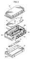
    1. An electric power distributor mountable on a motor vehicle for distributing electric power from a power source installed in the motor vehicle to a plurality of electric load units equipped in the vehicle, the power distributor comprising:
      a plurality of semiconductor operative elements which are incorporated in a power supply circuit from the power source to the electric load units;
      a control circuit board incorporated with a control circuit for controlling operation of the semiconductor operative elements, the control circuit board being arranged over the plurality of semiconductor operative elements, and having a heat transfer layer on a surface facing the plurality of semiconductor operative elements;
      a housing for accommodating the plurality of semiconductor operative elements and the control circuit board;
      a heat transfer member connected with the heat transfer layer of the control circuit board; and
      a heat releasing member provided on an outer surface of the housing and connected with the heat transfer member for releasing heat from an inside of the housing to an outside of the housing.
    2. The power distributor according to claim 1, wherein the plurality of semiconductor operative elements are disposed between the control circuit board and the heat releasing member.
    3. The power distributor according to claim 1 or 2, wherein the plurality of semiconductor operative elements are provided substantially on a plane, and the heat releasing member and the control circuit board are provided substantially in parallel to the plane.
    4. The power distributor according to any one of claims 1 to 3, wherein the heat transfer member includes a metallic bolt member that fixedly mounts the control circuit board on the housing, and is rendered in contact with the heat transfer layer and the heat releasing member.
    5. The power distributor according to claim 4, wherein the control circuit board is formed with a bolt insertion hole for passing the bolt member through the control circuit board, and the housing is formed with a hole for passing the bolt member through the housing.
    6. The power distributor according to claim 5, wherein the heat transfer layer of the control circuit board includes an area which covers an inner surface of the bolt insertion hole and comes into contact with a bottom surface of a head portion of the bolt member.
    EP02007062A 2001-03-30 2002-03-27 Electric power distributor for use in motor vehicle Expired - Fee Related EP1245455B1 (en)

    Applications Claiming Priority (2)

    Application Number Priority Date Filing Date Title
    JP2001101094 2001-03-30
    JP2001101094A JP4357762B2 (en) 2001-03-30 2001-03-30 Vehicle power distributor

    Publications (3)

    Publication Number Publication Date
    EP1245455A2 true EP1245455A2 (en) 2002-10-02
    EP1245455A3 EP1245455A3 (en) 2004-03-10
    EP1245455B1 EP1245455B1 (en) 2006-06-21

    Family

    ID=18954464

    Family Applications (1)

    Application Number Title Priority Date Filing Date
    EP02007062A Expired - Fee Related EP1245455B1 (en) 2001-03-30 2002-03-27 Electric power distributor for use in motor vehicle

    Country Status (4)

    Country Link
    US (1) US6522528B2 (en)
    EP (1) EP1245455B1 (en)
    JP (1) JP4357762B2 (en)
    DE (1) DE60212481T2 (en)

    Cited By (6)

    * Cited by examiner, † Cited by third party
    Publication number Priority date Publication date Assignee Title
    GB2425412A (en) * 2005-04-22 2006-10-25 Lear Corp Junction box not having fuses or relays
    EP1883285A3 (en) * 2006-07-27 2009-04-29 Deere & Company Cantilever mounted electronic module with rigid center backbone
    US7643297B2 (en) 2007-05-07 2010-01-05 Mitsubishi Electric Corporation Electronic control apparatus
    US8050006B2 (en) 2007-12-27 2011-11-01 Lear Corporation Gmbh Method and system of providing overload and short-circuit protection for switched mode power supply
    US20210291766A1 (en) * 2020-03-19 2021-09-23 Ellenberger & Poensgen Gmbh Power distributor of an electrical system of a motor vehicle
    DE112006002302B4 (en) 2005-09-02 2022-05-25 GM Global Technology Operations LLC (n. d. Ges. d. Staates Delaware) ELECTRICAL SYSTEM INCLUDING A POWER TRANSISTOR ARRANGEMENT, A BUSBAR AND A CIRCUIT BOARD ASSEMBLY

    Families Citing this family (44)

    * Cited by examiner, † Cited by third party
    Publication number Priority date Publication date Assignee Title
    DE60135405D1 (en) * 2000-03-21 2008-10-02 Autonetworks Technologies Ltd Power distributor for a motor vehicle and method of manufacture
    US7032695B2 (en) * 2002-01-16 2006-04-25 Rockwell Automation Technologies, Inc. Vehicle drive module having improved terminal design
    US7061775B2 (en) * 2002-01-16 2006-06-13 Rockwell Automation Technologies, Inc. Power converter having improved EMI shielding
    US7187568B2 (en) * 2002-01-16 2007-03-06 Rockwell Automation Technologies, Inc. Power converter having improved terminal structure
    US6972957B2 (en) * 2002-01-16 2005-12-06 Rockwell Automation Technologies, Inc. Modular power converter having fluid cooled support
    US6898072B2 (en) * 2002-01-16 2005-05-24 Rockwell Automation Technologies, Inc. Cooled electrical terminal assembly and device incorporating same
    US6965514B2 (en) * 2002-01-16 2005-11-15 Rockwell Automation Technologies, Inc. Fluid cooled vehicle drive module
    JP3910497B2 (en) * 2002-07-03 2007-04-25 株式会社オートネットワーク技術研究所 Power circuit waterproofing method and power module having power circuit
    US20040161960A1 (en) * 2002-11-21 2004-08-19 Autonetworks Technologies, Ltd. Vehicle-installed relay box
    US6717797B1 (en) * 2002-11-22 2004-04-06 Tyco Electronics Corporation Apparatus, methods and articles of manufacture for a module box with integrated components
    JP4173014B2 (en) 2003-01-17 2008-10-29 富士通株式会社 Heat sink and electronic device cooling apparatus and electronic device
    DE102004003048A1 (en) * 2003-01-22 2004-08-05 Marquardt Gmbh Electrical connecting element, especially for electrical tool switch, has pin protruding from fixing element on both sides to contact lead, contact surface, e.g. as in surface mount technology
    US7099155B2 (en) * 2003-02-14 2006-08-29 Autonetworks Technologies, Ltd. Distribution unit and electric connection box including the same
    US6743027B1 (en) * 2003-03-18 2004-06-01 Lear Corporation Remote zone connector and system
    US7120024B2 (en) * 2004-02-27 2006-10-10 Fujitsu Ten Limited Electronic control device
    JP2005312129A (en) * 2004-04-19 2005-11-04 Auto Network Gijutsu Kenkyusho:Kk Electric connection box
    WO2006011478A1 (en) * 2004-07-27 2006-02-02 Autonetworks Technologies, Ltd. Electric connection box
    DE102006028518A1 (en) * 2005-06-23 2007-02-01 AUTONETWORKS Technologies, LTD., Yokkaichi Electrical connector box
    DE102005050028A1 (en) * 2005-10-14 2007-04-19 Robert Bosch Gmbh Electric device, in particular for controlling a motor and / or regenerative electric machine
    US20070165376A1 (en) * 2006-01-17 2007-07-19 Norbert Bones Three phase inverter power stage and assembly
    JP4709032B2 (en) * 2006-02-22 2011-06-22 株式会社オートネットワーク技術研究所 Electrical junction box
    JP4736903B2 (en) * 2006-03-31 2011-07-27 株式会社ジェイテクト Electronic control unit
    JP4278680B2 (en) 2006-12-27 2009-06-17 三菱電機株式会社 Electronic control unit
    JP4408444B2 (en) * 2007-09-28 2010-02-03 株式会社日立製作所 Electronic control device using LC module structure
    JP5186877B2 (en) * 2007-10-15 2013-04-24 株式会社デンソー Semiconductor device
    JP2009119957A (en) * 2007-11-13 2009-06-04 Mitsubishi Electric Corp Electronic control device and its manufacturing method
    JP2009164536A (en) * 2008-01-10 2009-07-23 Denso Corp Driving device of electrical load
    JP4638923B2 (en) * 2008-03-31 2011-02-23 日立オートモティブシステムズ株式会社 Control device
    KR100999263B1 (en) * 2008-05-27 2010-12-07 기아자동차주식회사 Case structure of integrated package module for hybrid vehicle
    JP4684338B2 (en) * 2009-03-30 2011-05-18 三菱電機株式会社 Electronic control unit
    WO2012166379A1 (en) * 2011-05-31 2012-12-06 Eaton Corporation Plug-in composite power distribution assembly and system including same
    DE102011085650B4 (en) * 2011-11-03 2022-09-01 Robert Bosch Gmbh Attachment of a control unit for a transmission control module to a carrier plate
    DE102012021558A1 (en) * 2012-11-02 2014-05-08 Volkswagen Aktiengesellschaft Method for controlling and reading backup unit of motor vehicle, involves configuring control unit to control backup unit of vehicle according to change in state of securing elements so as to restore previous state of securing elements
    US9961786B2 (en) * 2013-11-19 2018-05-01 Continental Automotive Systems, Inc. Method and structure for limiting cover deflection in an ECU when exposed to high altitude environments
    KR101511596B1 (en) 2013-12-19 2015-04-14 현대오트론 주식회사 Heat Sink Structure of Controller for Vehicle Electronic Device and Motor Driven Power Steering Apparatus including Same
    US9293870B1 (en) * 2015-03-10 2016-03-22 Continental Automotive Systems, Inc. Electronic control module having a cover allowing for inspection of right angle press-fit pins
    US10231348B2 (en) 2015-05-28 2019-03-12 Yazaki Corporation Heat dissipation structure for connector module
    JP2016225066A (en) * 2015-05-28 2016-12-28 矢崎総業株式会社 Connector module
    JP6432792B2 (en) * 2015-09-29 2018-12-05 株式会社オートネットワーク技術研究所 Circuit structure and electrical junction box
    JP6404258B2 (en) * 2016-04-26 2018-10-10 矢崎総業株式会社 Electrical junction box and wire harness
    JP6884553B2 (en) * 2016-11-04 2021-06-09 エドワーズ株式会社 Assembling method of vacuum pump control device, vacuum pump, and vacuum pump control device
    JP6810893B2 (en) * 2017-06-14 2021-01-13 株式会社オートネットワーク技術研究所 Wiring unit
    JP6717266B2 (en) * 2017-06-28 2020-07-01 株式会社オートネットワーク技術研究所 Circuit device
    JP2022146388A (en) * 2021-03-22 2022-10-05 株式会社オートネットワーク技術研究所 circuit device

    Citations (3)

    * Cited by examiner, † Cited by third party
    Publication number Priority date Publication date Assignee Title
    US5602451A (en) * 1994-06-30 1997-02-11 Mitsubishi Denki Kabushiki Kaisha Electric power steering circuit device
    WO2000027685A1 (en) * 1998-11-11 2000-05-18 Trw Lucasvarity Electric Steering Ltd. Improvements relating to power steering
    DE19959023A1 (en) * 1999-12-08 2001-07-26 Bosch Gmbh Robert Housing for an electrical device

    Family Cites Families (4)

    * Cited by examiner, † Cited by third party
    Publication number Priority date Publication date Assignee Title
    US4498120A (en) * 1982-03-01 1985-02-05 Kaufman Lance R Electrical sub-assembly having a lead frame to be compressed between a circuit board and heat sink
    JPH10126963A (en) 1996-10-14 1998-05-15 Yazaki Corp Power supply distribution for vehicle
    JPH10150283A (en) 1996-11-19 1998-06-02 Nec Eng Ltd Heat radiation structure of printed-wiring board
    DE60135405D1 (en) * 2000-03-21 2008-10-02 Autonetworks Technologies Ltd Power distributor for a motor vehicle and method of manufacture

    Patent Citations (3)

    * Cited by examiner, † Cited by third party
    Publication number Priority date Publication date Assignee Title
    US5602451A (en) * 1994-06-30 1997-02-11 Mitsubishi Denki Kabushiki Kaisha Electric power steering circuit device
    WO2000027685A1 (en) * 1998-11-11 2000-05-18 Trw Lucasvarity Electric Steering Ltd. Improvements relating to power steering
    DE19959023A1 (en) * 1999-12-08 2001-07-26 Bosch Gmbh Robert Housing for an electrical device

    Cited By (9)

    * Cited by examiner, † Cited by third party
    Publication number Priority date Publication date Assignee Title
    GB2425412A (en) * 2005-04-22 2006-10-25 Lear Corp Junction box not having fuses or relays
    GB2425412B (en) * 2005-04-22 2007-03-07 Lear Corp Relayless and fuseless junction box
    US8570699B2 (en) 2005-04-22 2013-10-29 Lear Corporation Relayless and fuseless junction box
    DE112006002302B4 (en) 2005-09-02 2022-05-25 GM Global Technology Operations LLC (n. d. Ges. d. Staates Delaware) ELECTRICAL SYSTEM INCLUDING A POWER TRANSISTOR ARRANGEMENT, A BUSBAR AND A CIRCUIT BOARD ASSEMBLY
    EP1883285A3 (en) * 2006-07-27 2009-04-29 Deere & Company Cantilever mounted electronic module with rigid center backbone
    US7643297B2 (en) 2007-05-07 2010-01-05 Mitsubishi Electric Corporation Electronic control apparatus
    US8050006B2 (en) 2007-12-27 2011-11-01 Lear Corporation Gmbh Method and system of providing overload and short-circuit protection for switched mode power supply
    US20210291766A1 (en) * 2020-03-19 2021-09-23 Ellenberger & Poensgen Gmbh Power distributor of an electrical system of a motor vehicle
    US11653450B2 (en) * 2020-03-19 2023-05-16 Ellenberger & Poensgen Gmbh Power distributor of an electrical system of a motor vehicle

    Also Published As

    Publication number Publication date
    DE60212481T2 (en) 2007-06-14
    US6522528B2 (en) 2003-02-18
    US20020141143A1 (en) 2002-10-03
    JP2002293202A (en) 2002-10-09
    EP1245455A3 (en) 2004-03-10
    EP1245455B1 (en) 2006-06-21
    DE60212481D1 (en) 2006-08-03
    JP4357762B2 (en) 2009-11-04

    Similar Documents

    Publication Publication Date Title
    EP1245455B1 (en) Electric power distributor for use in motor vehicle
    US6785139B2 (en) Electric connection box
    JP3927017B2 (en) Circuit structure and manufacturing method thereof
    EP1150554B1 (en) Cooling structure for a vehicle control unit
    US6611066B2 (en) Power distributor for vehicle
    US6761567B2 (en) Electric power distribution unit for electric connection box and electric connection box
    US6797880B2 (en) Plastic frame for the mounting of an electronic heavy-current control unit
    US6472772B2 (en) Electric power distributor for use in motor vehicle
    US7137829B2 (en) Electric power distribution unit for electric connection box and electric connection box
    JPH1035375A (en) Connector and electrical connection box
    EP1178584B1 (en) Vehicle power distributor and method of producing the same
    JP4002074B2 (en) Automotive electrical unit
    WO2021111897A1 (en) Electrical connection box
    JP2003087938A (en) Electric junction box
    WO2020080248A1 (en) Circuit structure and electrical junction box
    JP2002325336A (en) Electrical connection box
    WO2020017470A1 (en) Substrate structure
    JP2022134365A (en) Energization control device
    AU2001273843B2 (en) Electronic control module for a vehicle
    JP2000308236A (en) Electrical connection box
    JP2004103816A (en) Electronic component mounting structure for large current control unit

    Legal Events

    Date Code Title Description
    PUAI Public reference made under article 153(3) epc to a published international application that has entered the european phase

    Free format text: ORIGINAL CODE: 0009012

    AK Designated contracting states

    Kind code of ref document: A2

    Designated state(s): AT BE CH CY DE DK ES FI FR GB GR IE IT LI LU MC NL PT SE TR

    AX Request for extension of the european patent

    Free format text: AL;LT;LV;MK;RO;SI

    PUAL Search report despatched

    Free format text: ORIGINAL CODE: 0009013

    AK Designated contracting states

    Kind code of ref document: A3

    Designated state(s): AT BE CH CY DE DK ES FI FR GB GR IE IT LI LU MC NL PT SE TR

    AX Request for extension of the european patent

    Extension state: AL LT LV MK RO SI

    RIC1 Information provided on ipc code assigned before grant

    Ipc: 7B 60R 16/02 A

    Ipc: 7H 05K 1/05 B

    17P Request for examination filed

    Effective date: 20040608

    AKX Designation fees paid

    Designated state(s): DE

    GRAP Despatch of communication of intention to grant a patent

    Free format text: ORIGINAL CODE: EPIDOSNIGR1

    GRAS Grant fee paid

    Free format text: ORIGINAL CODE: EPIDOSNIGR3

    GRAA (expected) grant

    Free format text: ORIGINAL CODE: 0009210

    AK Designated contracting states

    Kind code of ref document: B1

    Designated state(s): DE

    REF Corresponds to:

    Ref document number: 60212481

    Country of ref document: DE

    Date of ref document: 20060803

    Kind code of ref document: P

    PLBE No opposition filed within time limit

    Free format text: ORIGINAL CODE: 0009261

    STAA Information on the status of an ep patent application or granted ep patent

    Free format text: STATUS: NO OPPOSITION FILED WITHIN TIME LIMIT

    26N No opposition filed

    Effective date: 20070322

    PGFP Annual fee paid to national office [announced via postgrant information from national office to epo]

    Ref country code: DE

    Payment date: 20130320

    Year of fee payment: 12

    REG Reference to a national code

    Ref country code: DE

    Ref legal event code: R119

    Ref document number: 60212481

    Country of ref document: DE

    REG Reference to a national code

    Ref country code: DE

    Ref legal event code: R119

    Ref document number: 60212481

    Country of ref document: DE

    Effective date: 20141001

    PG25 Lapsed in a contracting state [announced via postgrant information from national office to epo]

    Ref country code: DE

    Free format text: LAPSE BECAUSE OF NON-PAYMENT OF DUE FEES

    Effective date: 20141001