EP1245263B1 - Fluid filtering member - Google Patents
Fluid filtering member Download PDFInfo
- Publication number
- EP1245263B1 EP1245263B1 EP02007063A EP02007063A EP1245263B1 EP 1245263 B1 EP1245263 B1 EP 1245263B1 EP 02007063 A EP02007063 A EP 02007063A EP 02007063 A EP02007063 A EP 02007063A EP 1245263 B1 EP1245263 B1 EP 1245263B1
- Authority
- EP
- European Patent Office
- Prior art keywords
- filter material
- layers
- filtering member
- rough
- fluid filtering
- Prior art date
- Legal status (The legal status is an assumption and is not a legal conclusion. Google has not performed a legal analysis and makes no representation as to the accuracy of the status listed.)
- Expired - Fee Related
Links
- 238000001914 filtration Methods 0.000 title claims description 53
- 239000012530 fluid Substances 0.000 title claims description 17
- 239000000463 material Substances 0.000 claims description 81
- 238000002844 melting Methods 0.000 claims description 9
- 230000008018 melting Effects 0.000 claims description 9
- 239000004745 nonwoven fabric Substances 0.000 claims description 6
- 239000000446 fuel Substances 0.000 description 35
- XEEYBQQBJWHFJM-UHFFFAOYSA-N Iron Chemical compound [Fe] XEEYBQQBJWHFJM-UHFFFAOYSA-N 0.000 description 30
- 238000004519 manufacturing process Methods 0.000 description 22
- 238000003466 welding Methods 0.000 description 21
- 229910052742 iron Inorganic materials 0.000 description 15
- 239000000835 fiber Substances 0.000 description 12
- 239000000853 adhesive Substances 0.000 description 10
- 230000001070 adhesive effect Effects 0.000 description 10
- -1 polypropylene Polymers 0.000 description 8
- 239000004743 Polypropylene Substances 0.000 description 6
- 229920000728 polyester Polymers 0.000 description 6
- 229920001155 polypropylene Polymers 0.000 description 6
- 238000000034 method Methods 0.000 description 5
- 229920000297 Rayon Polymers 0.000 description 4
- 229920006221 acetate fiber Polymers 0.000 description 4
- 239000011521 glass Substances 0.000 description 4
- 239000002964 rayon Substances 0.000 description 4
- 230000000694 effects Effects 0.000 description 3
- 238000005096 rolling process Methods 0.000 description 3
- 239000004698 Polyethylene Substances 0.000 description 2
- 239000004744 fabric Substances 0.000 description 2
- 235000000396 iron Nutrition 0.000 description 2
- 229920000573 polyethylene Polymers 0.000 description 2
- 239000011347 resin Substances 0.000 description 2
- 229920005989 resin Polymers 0.000 description 2
- 238000010276 construction Methods 0.000 description 1
- 238000005520 cutting process Methods 0.000 description 1
- 238000010438 heat treatment Methods 0.000 description 1
- 238000010348 incorporation Methods 0.000 description 1
- 239000007788 liquid Substances 0.000 description 1
- 238000012986 modification Methods 0.000 description 1
- 230000004048 modification Effects 0.000 description 1
- 239000002245 particle Substances 0.000 description 1
- 238000007789 sealing Methods 0.000 description 1
Images


Classifications
-
- B—PERFORMING OPERATIONS; TRANSPORTING
- B01—PHYSICAL OR CHEMICAL PROCESSES OR APPARATUS IN GENERAL
- B01D—SEPARATION
- B01D46/00—Filters or filtering processes specially modified for separating dispersed particles from gases or vapours
- B01D46/52—Particle separators, e.g. dust precipitators, using filters embodying folded corrugated or wound sheet material
- B01D46/521—Particle separators, e.g. dust precipitators, using filters embodying folded corrugated or wound sheet material using folded, pleated material
-
- B—PERFORMING OPERATIONS; TRANSPORTING
- B01—PHYSICAL OR CHEMICAL PROCESSES OR APPARATUS IN GENERAL
- B01D—SEPARATION
- B01D29/00—Filters with filtering elements stationary during filtration, e.g. pressure or suction filters, not covered by groups B01D24/00 - B01D27/00; Filtering elements therefor
- B01D29/01—Filters with filtering elements stationary during filtration, e.g. pressure or suction filters, not covered by groups B01D24/00 - B01D27/00; Filtering elements therefor with flat filtering elements
- B01D29/012—Making filtering elements
-
- B—PERFORMING OPERATIONS; TRANSPORTING
- B01—PHYSICAL OR CHEMICAL PROCESSES OR APPARATUS IN GENERAL
- B01D—SEPARATION
- B01D29/00—Filters with filtering elements stationary during filtration, e.g. pressure or suction filters, not covered by groups B01D24/00 - B01D27/00; Filtering elements therefor
- B01D29/01—Filters with filtering elements stationary during filtration, e.g. pressure or suction filters, not covered by groups B01D24/00 - B01D27/00; Filtering elements therefor with flat filtering elements
- B01D29/05—Filters with filtering elements stationary during filtration, e.g. pressure or suction filters, not covered by groups B01D24/00 - B01D27/00; Filtering elements therefor with flat filtering elements supported
- B01D29/07—Filters with filtering elements stationary during filtration, e.g. pressure or suction filters, not covered by groups B01D24/00 - B01D27/00; Filtering elements therefor with flat filtering elements supported with corrugated, folded or wound filtering sheets
- B01D29/072—Filters with filtering elements stationary during filtration, e.g. pressure or suction filters, not covered by groups B01D24/00 - B01D27/00; Filtering elements therefor with flat filtering elements supported with corrugated, folded or wound filtering sheets ring shaped
-
- B—PERFORMING OPERATIONS; TRANSPORTING
- B01—PHYSICAL OR CHEMICAL PROCESSES OR APPARATUS IN GENERAL
- B01D—SEPARATION
- B01D46/00—Filters or filtering processes specially modified for separating dispersed particles from gases or vapours
- B01D46/0001—Making filtering elements
-
- B—PERFORMING OPERATIONS; TRANSPORTING
- B01—PHYSICAL OR CHEMICAL PROCESSES OR APPARATUS IN GENERAL
- B01D—SEPARATION
- B01D46/00—Filters or filtering processes specially modified for separating dispersed particles from gases or vapours
- B01D46/10—Particle separators, e.g. dust precipitators, using filter plates, sheets or pads having plane surfaces
-
- B—PERFORMING OPERATIONS; TRANSPORTING
- B01—PHYSICAL OR CHEMICAL PROCESSES OR APPARATUS IN GENERAL
- B01D—SEPARATION
- B01D2275/00—Filter media structures for filters specially adapted for separating dispersed particles from gases or vapours
- B01D2275/10—Multiple layers
Definitions
- the invention relates to a fluid filtering member.
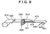
- a fuel filtering device 500 mounted on a vehicle is provided with a fuel filtering member 501 in a spiral structure disposed in a filter case 502.
- a manufacturing device illustrated in Fig. 8 is employed for manufacturing the fuel filtering member 501 and is supplied with a preprocessed filter material 510 as a rolled sheet at a left side of the manufacturing device (in the left in Fig. 8).
- the filter material 510 is primarily strained to a streaking means 520.
- the filter material 510 is applied with a pushing force of the streaking means 520 in a thickness direction of the filter material 510 at a central portion in a width direction thereof so as to be streaked at the central portion in the width direction thereof. Therefore, the filter material 510 can be easily folded along the streak.
- one side in the width direction of the filter material 510 is engageably meshed with a gear 530 from both sides in the thickness direction of the filter material 510 and is subject to a pushing force of the gear 530. Therefore, a corrugate (wave shape) 511 as a fuel passage is formed at the one side in the width direction of the filter material 510.
- the other side in the width direction of the filter material 510 is provided with a flat surface 512.
- a folded portion 513 is formed by folding the filter material 510 by a not-shown folding means along the streak at the central portion in the width direction of the filter material 510.
- the folded filter material 510 is then rolled by a core 540 in a spiral manner and is cut to a predetermined length so as to form the fuel filtering member 501. Further, an adhesive 551 (referring to Fig. 7) is applied by an adhesive applying means 550 to an inner side of the filter material 510 being rolled by the core 540 at a side having an opening portion 514. The opening portion 514 is arranged at an opposite side to the folded portion 513 in the width direction of the filter material 510. Therefore, relative surfaces of the filter material 510, i.e. the corrugate 511 and the flat surface 512 are adhered to each other by the adhesive 551 applied to the filter material 510.
- a fuel passage 515 is defined between the corrugate 511 and the flat surface 512 at the opening portion 514.
- the fluid introduced from the side of the opening portion 514 is filtered by the filter material 510 and is discharged from an opposite side of the filter material 510 in a width direction thereof.
- a filter material having the corrugate 511 and another filter material having the flat surface 512 are prepared.
- An edge portion at one side in a width direction of the filter material having the corrugate 511 is adhered with an edge portion at one side in a width direction of the other filter material having the flat surface 512 so as to form a bottom portion of a fluid passage.
- the bottom portion of the fluid passage corresponds to the folded portion 513 of the above described related art.
- the opening portion 514 is defined between an edge portion at an opposite side in the width direction of the filter material having the corrugate 511 and an edge portion at an opposite side in the width direction of the filter material having the flat surface 512.
- An inner side of the two filter materials is applied with the adhesive 551 and is rolled by the core 540 in the same manner as the above described related art. Therefore, relative surfaces of the two filter materials are adhered by the adhesive 551 so as to form the fuel filtering member 501.
- the above-described manufacturing process for manufacturing the fuel filtering member 510 causes the following drawbacks.
- Large-scale equipment may be required for processing the corrugate or for rolling the filter material and applying the adhesive 551 thereto. Further, the above complicated processes may lead to a high processing cost.
- the gear 530 is employed as a means for forming the corrugate 511 on the filter material 510.
- the filter material 510 may be torn due to the engagement of the gear 530. Therefore, the filtering performance may be deteriorated.
- EP 0 955 078 A1 discloses a fluid filtering member in accordance with the preamble of claim 1.
- the above described object is solved by a fluid filtering member according to claim 1.
- the fuel filtering member is provided with three layers, including a dense layer, with rough layers connected to both surfaces of the dense layer and serving as a passage.
- Large-scale equipment may not be required for processing the corrugate or for rolling the filter material, or for applying the adhesive thereto. Therefore, processing can be simplified.
- the filter material can be prevented from being torn due to forming a corrugate and connecting adjacent filter materials.
- a fuel passage can be assured by employing the filter material formed of the dense layer and the rough layers. Therefore, an additional passage is not required. Further, heat-welding of materials can be easily performed by using material with a low melting point to form the rough layers.
- Fig. 1 is a cross sectional view in a thickness direction of a filter material according to the invention
- a filtering member according to a first embodiment of the present invention is described with reference to Figs. 1, 2, and 3.
- the present invention is not intended to be limited to a fuel filtering member.
- a liquid filtering member employed as the fuel filtering member is described as a preferred embodiment of the invention.
- a filter material 10 is provided with a dense layer 16 at a central portion in a width direction of the filter material 10 and two rough layers 17 in which the dense layer 16 is sandwiched by and fixed to the rough layers 17.
- the filter material as a whole forms three layers.
- the rough layers 17 can effect a filtering performance whereby foreign particles over a predetermined size are filtered.
- the rough layers 17 are sufficiently rough, however, so as effect the flow of commonly used fuel. Further, the rough layers 17 should have a melting point low enough so as to be melted at a low heat.
- the dense layer 16 is required to have a more effective filtering performance than the rough layers 17 and should have a higher melting point than the melting point of the rough layers 17.
- a filter paper, or a non-woven fabric, for example, is selected as a material of the filter material 10.
- the non-woven fabric for the filter material 10 is made of a combination of a raw fiber and an adhering fiber.
- the raw fiber is made of a fiber, for example polyester, polypropylene, rayon, glass, and acetate fiber.
- the adhering fiber is made of a fabric, for example polyester, polypropylene, rayon, glass, and acetate fiber, of which surfaces are respectively coated with a resin having a low melting point, for example deformation polyester, deformation polyethylene, or deformation polypropylene.
- the fuel filtering member 10 is entirely made of the combination of the row fiber and the adhering fiber.
- the dense layer 16 made of the material with a higher density than the material of the rough layers 17 can be provided with a more effective filtering function than the rough layers 17.
- the filter material 10 is supplied for the manufacturing process with a rolled structure.
- a filtering member 120 is formed by primarily straining a sheet of the rolled filter material 10.
- the filter material 10 is applied with a pushing force of a streaking means 20 in a thickness direction of the filter material 10 at the central portion in a width direction thereof. Therefore, the filter material 10 is provided with a streak 11 at the central portion in the width direction so as to be easily folded in a longitudinal direction of the filter material 10.
- the filter material 10 is then folded by a not-shown folding means along the streak 11 so as to fold a one side 14 in the width direction of the filter member 10 on the other side 13 in the width direction thereof.
- the folded filter material 10 includes a folded portion 30, the one side 14 and the other side 13.
- the one side 14 and the other side 13 are elongated to both sides of the folded portion 30.
- the folded filter material 10 is rolled by a core 110 in a spiral manner as a cross sectional V-shaped member 100 having an opening portion 60 at an opposite the folded portion 30.
- the fuel filtering member 120 is formed by cutting the folded filter material 10 by a predetermined length.
- the V-shaped member 100 is rolled in the spiral manner, the one side 14 of the filter material 10 is arranged at an outer side of the spiral and the other side 13 is arranged at an inner side thereof. Therefore, the V-shaped member 100 forming the fuel filtering member 120 has both closed sides and an opening end so as to form a kind of sack.
- a cross sectional V-shaped member 101 illustrated at the left in Fig. 3 is at a stage immediately before being rolled by the core 110.
- the V-shaped member 100 illustrated at the right in Fig. 3 has been already rolled and is positioned at the most outer position of the spiral.
- An iron 70 as a heat welding means forms a heat welding portion 71 at an inner side of an edge portion of the iron 70.
- the heat welding portion 71 has actually a small size, for example approximately several millimeters.
- An outer side of the iron 70 is applied with an adiabatic process so as to form a non-heating portion 72.
- an inner surface 131 (a right edge of the V shape) of the V-shaped member 101 and an outer surface 140 (a left edge of the V shape) of the V-shaped member 100 are clipped by means of the heat welding portion 71 by inserting tip ends of the iron 70 into the opening portion 60 and an opening portion 61. Therefore, the inner surface 131 and the outer surface 140 are connected by the heat-welding.
- the core 110 has been continuously rotated so that the filtering member 120 can be rolled at any time.
- a clipping force of the heat welding portion 71 is set to be a force to allow a slipping of the heat-welded portion between the V-shaped bodies 100, 101.
- the iron 70 is moved in a radial direction in response to an increase of a radial length of the filter material 10 rolled by the core 11.
- the opening portions 60, 61 are clearly described in Fig. 3. However, the opening portions 60, 61 are little when the filter material 10 is actually rolled by the core 110. As described above, the rough layers 17 function as the fuel passage. After the filter material 10 is rolled by the core 110, the two relative rough layers 17 defining the opening portions 60, 61 become in contact with each other. As a result, the fuel passage is defined between the two rough layers 17 so as to allow sufficient flow of the fuel.
- the filter material employed according to the second embodiment is identical to the filter material illustrated in Fig. 1.
- the second embodiment is different from the first embodiment with respect to a manufacturing method of the fuel filtering member.
- the fuel filtering member according to the first embodiment is formed by folding the filter material along the streak at the central portion in the width direction thereof.
- the fuel filtering member according to the second embodiment is formed by employing two filter materials 300, 400 which has been separated beforehand.
- Each filter material 300, 400 according to the second embodiment is identical to the filter material 10 according to the first embodiment with respect to forming three layers including the dense layer and the rough layers sandwiching the dense layer therein, employing the filter paper or the non-woven fabric, for example, as the material thereof.
- the non-woven fabric for the filter material 10 is made of a combination of a raw fiber and an adhering fiber.
- the raw fiber is made of a fiber, for example polyester, polypropylene, rayon, glass, and acetate fiber.
- the adhering fiber is made of a fabric, for example polyester, polypropylene, rayon, glass, and acetate fiber, of which surfaces are respectively coated with a resin having a low melting point, for example deformation polyester, deformation polyethylene, or deformation polypropylene.
- a manufacturing device illustrated in Fig. 4 is employed for forming the fuel filtering member 120.
- the filter materials 300 and 400 as the rolled sheets are strained and are rolled in the spiral manner by the core 110.
- the rolled filter materials 300 and 400 are cut to a predetermined length so as to form the fuel filtering member 120.
- irons 75, 76 heat welding means
- edge portions are employed for connecting relative rough layers 17 by the heat-welding, respectively.
- Fig. 5 shows the condition in which two cross sectional V-shaped bodies 102, 103 being substantially identical to the V-shaped bodies 100, 101 shown in Fig. 3, for example, are formed by heat-welding the filter materials 300, 400.
- the iron 76 (the heat welding means) is employed for forming either the V-shaped member 102 or the V-shaped member 103. That is, the iron 76 is employed for heat-welding either a bottom portion 32 of the V-shaped body 102 or a bottom portion 33 of the V-shaped body 103. Therefore, the iron 76 is employed in a different way from the iron 75 for connecting the V-shaped bodies 102, 103.
- the two irons 75, 76 can be positioned as illustrated in Fig. 5.
- the heat-welding by the iron 76 is performed at an earlier stage than the welding by the iron 75.
- the heat Welding by the iron 75 is substantially same as the first embodiment. That is, the V-shaped member 103 is on a stage immediately before being rolled by the core 110. On the other hand, the V-shaped member 102 has been already rolled by the core 110 and is positioned at the most outer portion of the spiral. As illustrated in Fig.
- an inner surface 133 (a right edge of the V shape) of the V-shaped member 103 and an outer surface 142 (a left edge of the V shape) of the V-shaped member 102 are clipped by means of a heat welding portion by inserting tip ends of the iron 75 into the opening portions 62, 63 so as to heat-weld the clipped portion.
- the iron 76 is not required to be movable.
- the iron 76 is required to have a clipping force to allow a slipping of the welded surface of the V-shaped bodies 102, 103.
- the second embodiment can generate the same effect as the first embodiment of the invention. Further, the manufacturing cost for manufacturing the fuel filtering member 120 can be reduced by omitting the folding process.
- the filtering member is described as the fuel filtering member.
- the filtering member is not intended to be limited to the fuel filtering member. Rather any filtering member employed as a spiral type filter can be applicable.
- the known corrugate processing and rolling process of applying the adhesive are not required. Therefore, the manufacturing process can be simplified and the required time for manufacturing can be shortened. Therefore, the manufacturing cost can be reduced.
- durability and reliability of the fuel filtering member can be improved by preventing the filter material from being torn due to forming the corrugate thereon.
- the rolled filter material is provided with the dense layer and the rough layers so as to assure the fuel passage. Therefore, an additional passage is not required.
- the filter paper, or the non-woven fabric, for example is selected as the filter material. Therefore, the fuel passage can be easily assured by selecting the density of the rough layer and the dense layer. Further, the heat-welding can be performed easily by using material having a low melting point for the rough layers.
Landscapes
- Chemical & Material Sciences (AREA)
- Chemical Kinetics & Catalysis (AREA)
- Filtering Materials (AREA)
- Filtration Of Liquid (AREA)
- Lubrication Details And Ventilation Of Internal Combustion Engines (AREA)
- Separation Using Semi-Permeable Membranes (AREA)
- Laminated Bodies (AREA)
Applications Claiming Priority (2)
| Application Number | Priority Date | Filing Date | Title |
|---|---|---|---|
| JP2001094779A JP2002282626A (ja) | 2001-03-29 | 2001-03-29 | 液体用濾過体 |
| JP2001094779 | 2001-03-29 |
Publications (3)
| Publication Number | Publication Date |
|---|---|
| EP1245263A2 EP1245263A2 (en) | 2002-10-02 |
| EP1245263A3 EP1245263A3 (en) | 2003-07-23 |
| EP1245263B1 true EP1245263B1 (en) | 2006-06-28 |
Family
ID=18948927
Family Applications (1)
| Application Number | Title | Priority Date | Filing Date |
|---|---|---|---|
| EP02007063A Expired - Fee Related EP1245263B1 (en) | 2001-03-29 | 2002-03-27 | Fluid filtering member |
Country Status (4)
| Country | Link |
|---|---|
| US (1) | US20020139745A1 (ja) |
| EP (1) | EP1245263B1 (ja) |
| JP (1) | JP2002282626A (ja) |
| DE (1) | DE60212747T2 (ja) |
Families Citing this family (6)
| Publication number | Priority date | Publication date | Assignee | Title |
|---|---|---|---|---|
| JP2004239243A (ja) * | 2003-02-10 | 2004-08-26 | Toyota Motor Corp | 燃料供給装置 |
| US7704464B2 (en) * | 2004-09-17 | 2010-04-27 | 0783963 Bc Ltd. | Hydrocarbon processing devices and systems for engines and combustion equipment |
| JP2007113457A (ja) * | 2005-10-19 | 2007-05-10 | Tokyo Roki Co Ltd | 燃料フィルタ |
| US20080110469A1 (en) * | 2006-11-13 | 2008-05-15 | Stanley Weinberg | Strapless flexible tribo-charged respiratory facial mask and method |
| US20090277451A1 (en) * | 2006-11-13 | 2009-11-12 | Stanley Weinberg | Strapless cantilevered respiratory mask sealable to a user's face and method |
| JP2009106878A (ja) * | 2007-10-31 | 2009-05-21 | Denso Corp | 燃料フィルタ |
Family Cites Families (18)
| Publication number | Priority date | Publication date | Assignee | Title |
|---|---|---|---|---|
| US2397759A (en) * | 1942-04-17 | 1946-04-02 | Sigmund Miroslav | Filter |
| US2427862A (en) * | 1945-12-22 | 1947-09-23 | Int Harvester Co | Filter element |
| US3112184A (en) * | 1958-09-08 | 1963-11-26 | Corning Glass Works | Method of making ceramic articles |
| US3348695A (en) * | 1965-07-12 | 1967-10-24 | Rosaen Filter Co | Filter material |
| USB373916I5 (ja) * | 1970-08-08 | |||
| US4039457A (en) * | 1973-02-02 | 1977-08-02 | Robert Bosch G.M.B.H. | Coiled filter element for filtering of liquids |
| US3867294A (en) * | 1973-05-09 | 1975-02-18 | Pall Corp | Cylindrical filter elements with improved side seam seal |
| US4555342A (en) * | 1982-06-28 | 1985-11-26 | Grant Blake F | Ribbon filter apparatus |
| US4655447A (en) * | 1985-08-02 | 1987-04-07 | Dubrinsky Max M | Treadmill assembly |
| DE3613710C1 (de) * | 1986-04-23 | 1987-09-24 | Fahrleitungsbau Gmbh | Gehsicherung fuer eine Person in einem unterirdischen Kanal oder dergleichen,insbesondere in einem Kanalisationsrohr |
| GB2256601A (en) * | 1991-06-12 | 1992-12-16 | Domnick Hunter Ltd | Filter |
| GB2277458B (en) * | 1993-04-28 | 1996-08-14 | Pall Corp | Filters and filter manufacture |
| WO1996036415A1 (en) * | 1995-05-18 | 1996-11-21 | Parker-Hannifin Corporation | Compound layer resin bonded filter cartridge |
| US6099729A (en) * | 1996-03-01 | 2000-08-08 | Parker-Hannifin Corporation | Coreless non-metallic filter element |
| WO1999036129A1 (en) * | 1998-01-20 | 1999-07-22 | Precor Incorporated | Exercise treadmill |
| JP4231109B2 (ja) * | 1996-10-17 | 2009-02-25 | アレヴァ エンペー ゲゼルシャフト ミット ベシュレンクテル ハフツング | エーロゾルフィルタとその利用方法 |
| IT1303067B1 (it) * | 1998-05-06 | 2000-10-23 | Sogefi S P A | Filtro per fluidi con zone di filtrazione differenziate |
| US6500097B1 (en) * | 2000-06-19 | 2002-12-31 | Lawrence Hall | Rotary exercise device |
-
2001
- 2001-03-29 JP JP2001094779A patent/JP2002282626A/ja active Pending
-
2002
- 2002-03-25 US US10/103,715 patent/US20020139745A1/en not_active Abandoned
- 2002-03-27 EP EP02007063A patent/EP1245263B1/en not_active Expired - Fee Related
- 2002-03-27 DE DE60212747T patent/DE60212747T2/de not_active Expired - Fee Related
Also Published As
| Publication number | Publication date |
|---|---|
| EP1245263A3 (en) | 2003-07-23 |
| JP2002282626A (ja) | 2002-10-02 |
| EP1245263A2 (en) | 2002-10-02 |
| DE60212747T2 (de) | 2007-06-28 |
| US20020139745A1 (en) | 2002-10-03 |
| DE60212747D1 (de) | 2006-08-10 |
Similar Documents
| Publication | Publication Date | Title |
|---|---|---|
| US6193773B1 (en) | Dust filter bag | |
| US5804014A (en) | Process for providing a filter insert | |
| US5543007A (en) | Filter element manufacturing method | |
| US9486719B2 (en) | Filter element, device for folding a filter medium web and process for producing a zigzag-folded filter element | |
| US8366798B2 (en) | Filter and method of making | |
| US20040173303A1 (en) | Method for producing a connection interface in a filter element and device for producing the same | |
| CA2048086C (en) | A filter | |
| KR100413752B1 (ko) | 일회용 오물 닦기 시트의 제조 방법 | |
| JP3362453B2 (ja) | 濾過エレメント | |
| EP1306119B1 (en) | In-tank fuel filter | |
| JP5635600B2 (ja) | 多層媒体用の連結要素、フィルタ要素、および薄層媒体を連結する方法 | |
| EP1128892B2 (de) | Plattenfilterelement für ein luftfilter | |
| EP2320060A1 (en) | Fuel filter | |
| EP2547418B1 (de) | Verfahren zur herstellung eines zickzackförmig gefalteten filterelements | |
| US20050284807A1 (en) | Filter element and method for the production thereof | |
| JP2635231B2 (ja) | 円筒形フィルタ及びその製造方法 | |
| US8696857B2 (en) | Method for forming a filter mat | |
| EP0588922A1 (en) | FILTERS WITH DELTA-FOLDED FILTER MATERIAL. | |
| EP0450299A1 (de) | Filterelement aus einem zick-zack-förmig gefalteten ring- oder plattenförmig angeordneten Filterbahnmaterial | |
| EP1245263B1 (en) | Fluid filtering member | |
| US8221567B2 (en) | Filter media and system and method of manufacturing the same | |
| EP0691880B1 (en) | Filter device for the filtration of fluids | |
| WO2008124199A2 (en) | Closed-loop-bonded filter media and liner pleat block and method | |
| US6096211A (en) | Fluid filtering apparatus for vehicle, filter element and method for manufacturing same | |
| GB2274604A (en) | Filter element |
Legal Events
| Date | Code | Title | Description |
|---|---|---|---|
| PUAI | Public reference made under article 153(3) epc to a published international application that has entered the european phase |
Free format text: ORIGINAL CODE: 0009012 |
|
| AK | Designated contracting states |
Kind code of ref document: A2 Designated state(s): AT BE CH CY DE DK ES FI FR GB GR IE IT LI LU MC NL PT SE TR |
|
| AX | Request for extension of the european patent |
Free format text: AL;LT;LV;MK;RO;SI |
|
| 17P | Request for examination filed |
Effective date: 20030114 |
|
| PUAL | Search report despatched |
Free format text: ORIGINAL CODE: 0009013 |
|
| AK | Designated contracting states |
Designated state(s): AT BE CH CY DE DK ES FI FR GB GR IE IT LI LU MC NL PT SE TR |
|
| AX | Request for extension of the european patent |
Extension state: AL LT LV MK RO SI |
|
| RIC1 | Information provided on ipc code assigned before grant |
Ipc: 7B 01D 46/52 B Ipc: 7B 01D 46/10 B Ipc: 7B 01D 29/01 B Ipc: 7B 01D 46/12 A |
|
| AKX | Designation fees paid |
Designated state(s): DE FR GB |
|
| 17Q | First examination report despatched |
Effective date: 20040609 |
|
| GRAP | Despatch of communication of intention to grant a patent |
Free format text: ORIGINAL CODE: EPIDOSNIGR1 |
|
| GRAS | Grant fee paid |
Free format text: ORIGINAL CODE: EPIDOSNIGR3 |
|
| GRAA | (expected) grant |
Free format text: ORIGINAL CODE: 0009210 |
|
| RIN1 | Information on inventor provided before grant (corrected) |
Inventor name: KOGUCHI, YOSHIICHI,C/O KYOSAN DENKI CO., LTD. |
|
| RAP1 | Party data changed (applicant data changed or rights of an application transferred) |
Owner name: KYOSAN DENKI CO., LTD. |
|
| AK | Designated contracting states |
Kind code of ref document: B1 Designated state(s): DE FR GB |
|
| REG | Reference to a national code |
Ref country code: GB Ref legal event code: FG4D |
|
| REF | Corresponds to: |
Ref document number: 60212747 Country of ref document: DE Date of ref document: 20060810 Kind code of ref document: P |
|
| ET | Fr: translation filed | ||
| PLBE | No opposition filed within time limit |
Free format text: ORIGINAL CODE: 0009261 |
|
| STAA | Information on the status of an ep patent application or granted ep patent |
Free format text: STATUS: NO OPPOSITION FILED WITHIN TIME LIMIT |
|
| 26N | No opposition filed |
Effective date: 20070329 |
|
| GBPC | Gb: european patent ceased through non-payment of renewal fee |
Effective date: 20070327 |
|
| REG | Reference to a national code |
Ref country code: FR Ref legal event code: ST Effective date: 20071130 |
|
| PG25 | Lapsed in a contracting state [announced via postgrant information from national office to epo] |
Ref country code: DE Free format text: LAPSE BECAUSE OF NON-PAYMENT OF DUE FEES Effective date: 20071002 |
|
| PG25 | Lapsed in a contracting state [announced via postgrant information from national office to epo] |
Ref country code: GB Free format text: LAPSE BECAUSE OF NON-PAYMENT OF DUE FEES Effective date: 20070327 |
|
| PG25 | Lapsed in a contracting state [announced via postgrant information from national office to epo] |
Ref country code: FR Free format text: LAPSE BECAUSE OF NON-PAYMENT OF DUE FEES Effective date: 20070402 |