EP1244948B1 - Thermostatic mixing device with arrangement to increase mixing - Google Patents
Thermostatic mixing device with arrangement to increase mixing Download PDFInfo
- Publication number
- EP1244948B1 EP1244948B1 EP00947055A EP00947055A EP1244948B1 EP 1244948 B1 EP1244948 B1 EP 1244948B1 EP 00947055 A EP00947055 A EP 00947055A EP 00947055 A EP00947055 A EP 00947055A EP 1244948 B1 EP1244948 B1 EP 1244948B1
- Authority
- EP
- European Patent Office
- Prior art keywords
- partition
- inlet passage
- thermostatic
- mixing chamber
- water
- Prior art date
- Legal status (The legal status is an assumption and is not a legal conclusion. Google has not performed a legal analysis and makes no representation as to the accuracy of the status listed.)
- Expired - Lifetime
Links
- XLYOFNOQVPJJNP-UHFFFAOYSA-N water Substances O XLYOFNOQVPJJNP-UHFFFAOYSA-N 0.000 claims abstract description 91
- 238000005192 partition Methods 0.000 claims abstract description 38
- 230000002093 peripheral effect Effects 0.000 claims description 7
- 238000007599 discharging Methods 0.000 claims description 4
- 238000004891 communication Methods 0.000 claims description 2
- 238000010276 construction Methods 0.000 description 7
- 238000004519 manufacturing process Methods 0.000 description 5
- 239000012530 fluid Substances 0.000 description 2
- 239000000203 mixture Substances 0.000 description 2
- 230000001276 controlling effect Effects 0.000 description 1
- 230000003247 decreasing effect Effects 0.000 description 1
- 230000001419 dependent effect Effects 0.000 description 1
- 230000000694 effects Effects 0.000 description 1
- 230000004048 modification Effects 0.000 description 1
- 238000012986 modification Methods 0.000 description 1
- 230000001737 promoting effect Effects 0.000 description 1
- 230000001105 regulatory effect Effects 0.000 description 1
- 238000007789 sealing Methods 0.000 description 1
Images

Classifications
-
- G—PHYSICS
- G05—CONTROLLING; REGULATING
- G05D—SYSTEMS FOR CONTROLLING OR REGULATING NON-ELECTRIC VARIABLES
- G05D23/00—Control of temperature
- G05D23/01—Control of temperature without auxiliary power
- G05D23/13—Control of temperature without auxiliary power by varying the mixing ratio of two fluids having different temperatures
- G05D23/1306—Control of temperature without auxiliary power by varying the mixing ratio of two fluids having different temperatures for liquids
- G05D23/132—Control of temperature without auxiliary power by varying the mixing ratio of two fluids having different temperatures for liquids with temperature sensing element
- G05D23/134—Control of temperature without auxiliary power by varying the mixing ratio of two fluids having different temperatures for liquids with temperature sensing element measuring the temperature of mixed fluid
Definitions
- This invention relates to a thermostatic mixing valve according to the preamble portion of claim 1, and more particularly to a construction within a thermostatic valve that increases mixing of cold and hot water supplied to the mixing chamber.
- Hot water and cold water supplied to a thermostatic mixing valve must be efficiently mixed in order for a thermostatic mixing valve to optimally perform its thermostatic function.
- the water must be sufficiently mixed before it comes into contact with the thermostatic element which controls the operation of the thermostatic valve.
- the thermostatic element includes a wax filled case and a piston which is moved by thermal expansion of the contained wax. Consequently, in many better quality thermostatic mixing valves, structures are introduced to promote early and complete mixing of the cold water and hot water supplied to the mixing device before the mixed water comes into contact with the case.
- Document DE-C-44 23 240 discloses a disc mounted on the thermostatic element.
- the disc periphery is located close to the hot water intake apertures located in the perimeter wall of the mixing chamber.
- the cold water enters the mixing chamber via a narrow space between the periphery of the disc and the perimeter wall of the mixing chamber. In this way, the two currents of cold water and hot water meet at right angles to each other to provide a certain level of mixing.
- this known construction has some disadvantages. First of all, an additional element in the form of a disc is introduced which increases the cost of manufacture and complicates assembly of the thermostatic mixing device.
- the disc needs to be positioned to form a narrow annular space within the mixing chamber adjacent the perimeter wall of the mixing chamber thereby calling for the necessity of precise manufacturing tolerances, especially with regards to the centering of the disc.
- the necessity for the space to be narrow in order to be effective undesirably reduces in the maximum flow rate provided by the mixing device.
- Document US-A-5 356 074 forming the preamble portion of claim 1 discloses a fluid mixing device which can adjust for temperature fluctuations of fluids.
- a thermal expansion element drives a reciprocating disk member with a portion which extends into and preferably through a common inlet for introducing hot and cold water into a cavity. This feature provides advantages in mixing the flow of the hot and cold water prior to contact with the thermal expansion element. Its design also reduces inertial forces to move the disk member as only a single seal is required.
- thermostatic mixing valve construction capable of effectively promoting early mixing of the cold water and the hot water supplied to a mixing device by a particular arrangement of existing elements without the addition of an added element.
- a construction that does not require overly precise manufacturing tolerances or does not appreciably increases the cost of production of a thermostatic mixing device. Another need is to reduce the phenomenon of dynamic dragging to the point where it becomes negligible in such a thermostatic valve and where the construction does not impose restrictive limits on the maximum flow rate admitted by the mixing valve.
- a thermostatic mixing valve which includes a housing with an inlet passage for hot water, an inlet passage for cold water, a mixing chamber in communication with the inlet passages, and an outlet for discharging mixed water from the mixing chamber, as well as a thermostatically controlled slide valve slidably mounted in the mixing chamber, for controlling the extent of opening and closing of the inlet passages, wherein a partition is located in the mixing chamber within the slide valve between the inlet passages, the partition being affixedly connected to the slide valve, wherein a spring is located in the housing and connected to the slide valve to bias the slide valve in a direction corresponding to an opening of the inlet passage for hot water and to a closing of the inlet passage for cold water, wherein a thermostatic element operating by thermal expansion is operably interposed between the partition and the housing to assist the slide valve to move in a direction corresponding to a closing of the inlet passage for hot water and to an opening of the inlet passage for cold water when the thermostatic element undergoes thermal expansion, where
- the slide valve is annular in shape about a central axis, with the inlet passage for hot water and the inlet passage for cold water being circumferentially arcuate about the central axis, wherein the partition has a plurality of crossing passages circumferentially spaced in proximity to the periphery of the partition, and wherein the inclined surface is annular in shape.
- the inclined surface is substantially rectilinear in section and forms a frusto-conical surface.
- the inclined surface is curvilinear in section and forms part of a toroidal surface.
- the housing includes a body member which houses an inlet port operably connected to the inlet passage for hot water and an inlet port operably connected to the inlet passage for cold water, a first insert member and a second insert member which are arranged in the body member, and a perimeter wall defining the mixing chamber, wherein the inlet passage for cold water is located between the perimeter wall and the first insert member, wherein the inlet passage for hot water is located between the perimeter wall and the second insert member, and wherein the inclined surface is formed on the second insert member.
- the slide valve is slidably movable in relation to the perimeter wall.
- perimeter wall and the partition may be formed in a separate member mounted in the body member, wherein the separate member, and the first and second insert members are connected together to form a cartridge assembly which houses the thermostatic element and the spring.
- an inner facing peripheral surface of the second insert member is interposed between the inclined surface and the outlet for discharging mixed water from the mixing chamber, and is inclined in a direction away from the central axis as its distance from the partition increases.
- the cold water which enters the mixing valve and passes through the slidable valve is admitted to the mixing chamber via the peripheral passages of the partition, preferably in the form of several substantially parallel jets which are close to the perimeter wall of the mixing chamber.
- Hot water which enters the mixing valve and comes through the slide valve is admitted to the mixing chamber in contact with the inclined surface and consequently flows in a direction which is towards the interior and towards the partition.
- the flow of hot water encounters the flow of cold water presenting an axial component of opposed velocities so that a high turbulence is generated which causes very effective mixing of the hot and cold flows before they come into contact with the thermostatic element.
- the inner facing peripheral surface of the second insert member which may also be inclined as described, causes a cavitation which, in its turn, then increases the turbulence, which makes mixing more effective.
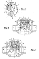
- FIG. 1 a fragmentary view of a thermostatic mixing valve is shown incorporating one embodiment of the invention.
- the operating handle and safety components and components in the lower part to adapt the thermostatic mixing valve to a faucet tap are not shown and form no part of the invention.
- the valve includes a body 1 with an inlet port 2 for intake of hot water, an inlet port 3 for intake of cold water, and an outlet or discharge port 4 for delivery of mixed water at a regulated temperature.
- Connecting conduits 5 and 6 run from respective ports 2 and 3 to carry the hot water and water to a mixing chamber 7.
- the mixing chamber 7 is defined by a perimeter member wall 8 that can be annular in shape.
- the wall member 8 slideably seats a valve 9 that carries a partition 10.
- the thermostatic valve has a first stationary insert member 12 and a second stationary insert member 13.
- the insert members 12 and 13 have generally annular perimeters.
- the stationary insert members 12 and 13 and the perimeter wall member 8 of the mixing chamber are statically secured together in body 1.
- One or more of the stationary insert members 12 and 13 can, if desired, be constructed integrally as one piece with the perimeter wall member 8 of the mixing chamber.
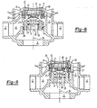
- Figure 8 illustrates where insert 13 is formed integrally with wall member 8.
- one of the insert members may be integrally formed with body 1.
- Figure 9 illustrates an embodiment where insert 13 is formed integrally with body 1.
- the perimeter member wall 8 of the mixing chamber and the two stationary inserts 12 and 13 may be attached to each other firmly, so that they can be installed in or removed from body 1 as a cartridge unit as illustrated in Figure 6.
- the outer shell of the cartridge may be formed by the wall 8, as in the embodiment shown.
- the inserts 12 and 13 may also be mounted directly in body I where in this case the peripheral wall member 8 of the mixing chamber may be integrally formed with the body 1 itself as illustrated in Figure 7.
- the body 1, installed insert members 12 and 13, and wall member 8 can be referred together as the housing
- Passages 16 are located between the first stationary component 12 and the perimeter wall member 8.
- the passages 16 allow the cold water to flow from connecting conduit 5 towards the interior of the mixing chamber 7.
- Passages 17 are located between the second stationary component 13 and the perimeter wall 8.
- the passages 17 allow the hot water to flow from connecting conduit 6 towards the interior of the mixing chamber 7.
- Passages 16 and 17 can be arcuate in shape circumferentially extending about the central axis 26. In one embodiment, passages 16 and 17 can be annular in shape completely surrounding central axis 26.
- adjustable gaps 16a and 17a for the flow of water from passages 16 for the cold water and from passages 17 for the hot water are controlled in a manner already well-known by the sliding movement of the slide valve 9 axially between inserts 12 and 13 in response to various already well-known operating criteria for the thermostatic mixing valve.
- a thermostatic element 18 of the type which operates by thermal expansion is mounted to partition 10 of the valve 9. Its moving element or piston 27 acts against the first stationary component 12 by means of safety elements which can also be of any kind and are already well-known and not shown for simplicity of the drawing.
- the thermostatic element 18 extends into the mixing chamber 7 and registers the temperature of the mixed water therein and expands or contracts correspondingly.
- the thermostatic element 18 expands due to an increase in the temperature of the mixed water which is in contact with it.
- the thermostatic element 18 causes the valve 9 secured with partition 10 to move in the direction which will reduce the clearance gap 17a for intake of hot water and increase the clearance of gap 16a for intake of cold water so as to hinder an increase in the temperature of the mixed water and consequently stabilize the temperature.
- the spring 19 acts both on the partition of the valve and on any other part secured to the valve, for example, the thermostatic element 18 itself.
- Crossing passages 11 are peripherally located in partition 10 of valve 9. Cold water from intake passages 16 must run through crossing passages 11 to reach the mixing chamber 7. The cold water therefore enters the mixing chamber in the form of many substantially parallel jets close to the perimeter wall member 8 in an axially directed velocity away from partition 10.
- the stationary insert member 13 which defines the intake passages 17 for hot water has at least one internal surface 14 which is inclined towards the central axis 26 of the interior of the mixing chamber 7 and towards the partition 10.
- the flow of hot water which enter the mixing chamber 7 is directed by this inclined surface 14 and therefore possesses a component of velocity directed radially towards the interior center axis 26 and a component of velocity directed axially towards the partition 10.
- the part of the inclined surface 14 of the second stationary insert member 13 may be, in section, substantially rectilinear, as shown in Figures 1, 2, and 4 such that the inclined surface forms part of a substantially frusto-conical surface.
- the inclined surface 14 of the second stationary component 13 maybe, in section, curvilinear, as shown in Figures 3 and 5, so that the inclined surface forms part of a substantially toridal surface.
- the surface 14 may also in fact have various other shapes provided that it includes an inclination towards the central axis 26 of the mixing chamber 7 and towards the partition 10.
- Figures 4 and 5 show a structure for further intensifying the turbulence in the mixing area and thus the efficiency of mixing of hot water and cold water which is obtained.
- An internal peripheral wall 15 of the second stationary insert member 13 has an inclination in a direction which will present at every point an increase in the distance from the axis 26 to the device as the distance from the partition 10 increases. This arrangement causes a cavitation in the flow of mixed water which, after entering the mixing chamber 7, is directed towards the discharge outlet 4 with a consequent increase in the turbulence and the efficiency of the mixing.
- the inclined surface 15 can also be substantially rectilinear in section, as shown in Figure 4, or may be curvilinear or of another shape than that shown as long as the cross sectional area of the cavity increases as distance from 10 increases.
Landscapes
- Physics & Mathematics (AREA)
- General Physics & Mathematics (AREA)
- Engineering & Computer Science (AREA)
- Automation & Control Theory (AREA)
- Multiple-Way Valves (AREA)
- Temperature-Responsive Valves (AREA)
- Apparatuses For Bulk Treatment Of Fruits And Vegetables And Apparatuses For Preparing Feeds (AREA)
- Mixers With Rotating Receptacles And Mixers With Vibration Mechanisms (AREA)
- Processing And Handling Of Plastics And Other Materials For Molding In General (AREA)
Applications Claiming Priority (3)
| Application Number | Priority Date | Filing Date | Title |
|---|---|---|---|
| ITTO990581 | 1999-07-06 | ||
| IT1999TO000581A IT1308789B1 (it) | 1999-07-06 | 1999-07-06 | Dispositivo miscelatore termostatico con disposizione per incrementarela miscelazione. |
| PCT/US2000/018466 WO2001002923A1 (en) | 1999-07-06 | 2000-07-06 | Thermostatic mixing device with arrangement to increase mixing |
Publications (3)
| Publication Number | Publication Date |
|---|---|
| EP1244948A1 EP1244948A1 (en) | 2002-10-02 |
| EP1244948A4 EP1244948A4 (en) | 2003-04-02 |
| EP1244948B1 true EP1244948B1 (en) | 2005-11-02 |
Family
ID=11417941
Family Applications (1)
| Application Number | Title | Priority Date | Filing Date |
|---|---|---|---|
| EP00947055A Expired - Lifetime EP1244948B1 (en) | 1999-07-06 | 2000-07-06 | Thermostatic mixing device with arrangement to increase mixing |
Country Status (12)
| Country | Link |
|---|---|
| EP (1) | EP1244948B1 (it) |
| CN (1) | CN1229704C (it) |
| AT (1) | ATE308776T1 (it) |
| AU (1) | AU6072300A (it) |
| CA (1) | CA2377400C (it) |
| DE (1) | DE60023745T2 (it) |
| DK (1) | DK1244948T3 (it) |
| ES (1) | ES2250162T3 (it) |
| IT (1) | IT1308789B1 (it) |
| MX (1) | MXPA02000081A (it) |
| TW (1) | TW466390B (it) |
| WO (1) | WO2001002923A1 (it) |
Cited By (1)
| Publication number | Priority date | Publication date | Assignee | Title |
|---|---|---|---|---|
| US8544760B2 (en) | 2001-08-24 | 2013-10-01 | Magarl, Llc | Mixing valve |
Families Citing this family (9)
| Publication number | Priority date | Publication date | Assignee | Title |
|---|---|---|---|---|
| GB2392223B (en) * | 2002-06-26 | 2006-05-31 | Kohler Mira Ltd | Improvements in or relating to thermostatic mixing valves |
| GB2392225B (en) * | 2002-06-26 | 2006-09-20 | Kohler Mira Ltd | Improvements in or relating to thermostatic mixing valves |
| CN100520135C (zh) * | 2003-09-25 | 2009-07-29 | 绿色工业有限公司 | 用于混合冷热液体的单杆阀的温度限制设备 |
| GB0427420D0 (en) | 2004-12-15 | 2005-01-19 | Kohler Mira Ltd | Improvements in or relating to thermostatic mixing valves |
| CN100516605C (zh) * | 2007-06-04 | 2009-07-22 | 潘兆铿 | 一种混合调节恒温水阀 |
| CA3116048C (en) | 2011-10-22 | 2023-01-03 | Magarl, Llc | Methods and apparatus for creating turbulence in a thermostatic mixing valve |
| FR3003046B1 (fr) * | 2013-03-07 | 2015-04-03 | Vernet | Cartouche thermostatique de regulation de fluide chaud et froid a melanger |
| FR3071299B1 (fr) | 2017-09-21 | 2019-11-15 | Novares France | Vanne thermostatique pour vehicule automobile |
| FR3116878B1 (fr) * | 2020-11-27 | 2022-12-02 | Vernet | Dispositif pour un système de robinetterie |
Family Cites Families (9)
| Publication number | Priority date | Publication date | Assignee | Title |
|---|---|---|---|---|
| GB1095924A (en) * | 1965-08-24 | 1967-12-20 | Richard Harding | Improvements in or relating to thermally controlled mixing valves |
| IT949211B (it) * | 1972-02-29 | 1973-06-11 | Knapp Alfons | Miscelatore termostatico per impianti idraulici |
| IT999835B (it) * | 1973-11-28 | 1976-03-10 | Knapp Alfons | Dispositivo miscelatore termostati co perfezionato per impianti idrau lici |
| FR2602502B1 (fr) * | 1986-08-11 | 1989-07-28 | Trubert Ets Rene | Perfectionnements aux dispositifs melangeurs thermostatiques, en particulier pour la distribution d'eau |
| US5135163A (en) * | 1991-04-11 | 1992-08-04 | Nakwon Cho | Three-way temperature regulator valve containing separate valve assemblies |
| TW226429B (it) * | 1992-07-20 | 1994-07-11 | Toto Ltd | |
| US5356074A (en) * | 1993-11-05 | 1994-10-18 | Jacob Delafon | Thermostatic mixing device |
| US5379936A (en) * | 1993-11-19 | 1995-01-10 | Lawler Manufacturing Co., Inc. | Flow control valve assembly |
| IT1295061B1 (it) * | 1997-09-24 | 1999-04-27 | Macrifin Spa | Valvola miscelatrice termostatica |
-
1999
- 1999-07-06 IT IT1999TO000581A patent/IT1308789B1/it active
-
2000
- 2000-07-06 CN CN00809900.6A patent/CN1229704C/zh not_active Expired - Fee Related
- 2000-07-06 AT AT00947055T patent/ATE308776T1/de not_active IP Right Cessation
- 2000-07-06 DK DK00947055T patent/DK1244948T3/da active
- 2000-07-06 MX MXPA02000081A patent/MXPA02000081A/es active IP Right Grant
- 2000-07-06 DE DE60023745T patent/DE60023745T2/de not_active Expired - Lifetime
- 2000-07-06 WO PCT/US2000/018466 patent/WO2001002923A1/en not_active Ceased
- 2000-07-06 EP EP00947055A patent/EP1244948B1/en not_active Expired - Lifetime
- 2000-07-06 ES ES00947055T patent/ES2250162T3/es not_active Expired - Lifetime
- 2000-07-06 AU AU60723/00A patent/AU6072300A/en not_active Abandoned
- 2000-07-06 CA CA002377400A patent/CA2377400C/en not_active Expired - Fee Related
- 2000-09-26 TW TW089119873A patent/TW466390B/zh not_active IP Right Cessation
Cited By (2)
| Publication number | Priority date | Publication date | Assignee | Title |
|---|---|---|---|---|
| US8544760B2 (en) | 2001-08-24 | 2013-10-01 | Magarl, Llc | Mixing valve |
| US10216203B2 (en) | 2001-08-24 | 2019-02-26 | Magarl, Llc | Mixing valve |
Also Published As
| Publication number | Publication date |
|---|---|
| TW466390B (en) | 2001-12-01 |
| DE60023745D1 (de) | 2005-12-08 |
| CN1367888A (zh) | 2002-09-04 |
| AU6072300A (en) | 2001-01-22 |
| ATE308776T1 (de) | 2005-11-15 |
| ES2250162T3 (es) | 2006-04-16 |
| EP1244948A1 (en) | 2002-10-02 |
| DK1244948T3 (da) | 2006-03-20 |
| ITTO990581A1 (it) | 2001-01-06 |
| DE60023745T2 (de) | 2006-08-03 |
| MXPA02000081A (es) | 2003-05-23 |
| WO2001002923A1 (en) | 2001-01-11 |
| EP1244948A4 (en) | 2003-04-02 |
| CA2377400C (en) | 2004-09-21 |
| CN1229704C (zh) | 2005-11-30 |
| IT1308789B1 (it) | 2002-01-10 |
| CA2377400A1 (en) | 2001-01-11 |
Similar Documents
| Publication | Publication Date | Title |
|---|---|---|
| EP1244948B1 (en) | Thermostatic mixing device with arrangement to increase mixing | |
| US6471132B1 (en) | Thermostatic mixing device with arrangement to increase mixing | |
| US10678277B2 (en) | Mixing valve | |
| US7845574B2 (en) | Cartridge for a mixer faucet, faucet comprising a cartridge of this type, and thermostatic assembly to be fitted together with this cartridge | |
| CN101523322B (zh) | 具有同心的温度和流量控制装置的恒温阀芯及设有这种阀芯的混合龙头 | |
| FI102633B (fi) | Kovaa materiaalia olevilla levyillä varustettu patruuna yksikahvaista säätöhanaa varten | |
| CN100533323C (zh) | 冷热流体混合用的温度调节芯组件与装配所述芯组件的冷热调控旋塞 | |
| CA2135359A1 (en) | Flow control valve assembly | |
| KR20010098456A (ko) | 오일 냉각 및 온도조절장치 | |
| JPH0340269B2 (it) | ||
| JP2702648B2 (ja) | 改良流量制御装置 | |
| JPH10184325A (ja) | 面積差を有するピストンを備えたエンジンバルブアクチュエータ | |
| US5054517A (en) | One-way restrictor | |
| CN111664269B (zh) | 恒温阀芯和恒温水龙头 | |
| US20040016816A1 (en) | Thermostatic valve for sanitary fixtures | |
| US5701985A (en) | Fluid friction clutch | |
| US3217697A (en) | Thermostatically controlled valve | |
| KR100320083B1 (ko) | 개선된자동재순환밸브 | |
| US5134975A (en) | Thermostatically controlled hydraulic fan clutch | |
| US2829834A (en) | Poppet type thermostat valve | |
| EP3708885B1 (en) | Improved dispensing cartridge for dispensing water in a water system | |
| CN210106669U (zh) | 恒温阀芯和恒温水龙头 | |
| CN109313457B (zh) | 混合单元和包括这种混合单元的混合龙头 | |
| EP0829041B1 (en) | Thermostatically controlled mixing valve | |
| RU2042074C1 (ru) | Смесительный кран |
Legal Events
| Date | Code | Title | Description |
|---|---|---|---|
| PUAI | Public reference made under article 153(3) epc to a published international application that has entered the european phase |
Free format text: ORIGINAL CODE: 0009012 |
|
| 17P | Request for examination filed |
Effective date: 20020103 |
|
| AK | Designated contracting states |
Kind code of ref document: A1 Designated state(s): AT BE CH CY DE DK ES FI FR GB GR IE IT LI LU MC NL PT SE |
|
| AX | Request for extension of the european patent |
Free format text: AL;LT;LV;MK;RO;SI |
|
| A4 | Supplementary search report drawn up and despatched |
Effective date: 20030218 |
|
| 17Q | First examination report despatched |
Effective date: 20030616 |
|
| GRAP | Despatch of communication of intention to grant a patent |
Free format text: ORIGINAL CODE: EPIDOSNIGR1 |
|
| GRAS | Grant fee paid |
Free format text: ORIGINAL CODE: EPIDOSNIGR3 |
|
| GRAA | (expected) grant |
Free format text: ORIGINAL CODE: 0009210 |
|
| AK | Designated contracting states |
Kind code of ref document: B1 Designated state(s): AT BE CH CY DE DK ES FI FR GB GR IE IT LI LU MC NL PT SE |
|
| PG25 | Lapsed in a contracting state [announced via postgrant information from national office to epo] |
Ref country code: BE Free format text: LAPSE BECAUSE OF FAILURE TO SUBMIT A TRANSLATION OF THE DESCRIPTION OR TO PAY THE FEE WITHIN THE PRESCRIBED TIME-LIMIT Effective date: 20051102 Ref country code: CH Free format text: LAPSE BECAUSE OF FAILURE TO SUBMIT A TRANSLATION OF THE DESCRIPTION OR TO PAY THE FEE WITHIN THE PRESCRIBED TIME-LIMIT Effective date: 20051102 Ref country code: NL Free format text: LAPSE BECAUSE OF FAILURE TO SUBMIT A TRANSLATION OF THE DESCRIPTION OR TO PAY THE FEE WITHIN THE PRESCRIBED TIME-LIMIT Effective date: 20051102 Ref country code: FI Free format text: LAPSE BECAUSE OF FAILURE TO SUBMIT A TRANSLATION OF THE DESCRIPTION OR TO PAY THE FEE WITHIN THE PRESCRIBED TIME-LIMIT Effective date: 20051102 Ref country code: LI Free format text: LAPSE BECAUSE OF FAILURE TO SUBMIT A TRANSLATION OF THE DESCRIPTION OR TO PAY THE FEE WITHIN THE PRESCRIBED TIME-LIMIT Effective date: 20051102 Ref country code: AT Free format text: LAPSE BECAUSE OF FAILURE TO SUBMIT A TRANSLATION OF THE DESCRIPTION OR TO PAY THE FEE WITHIN THE PRESCRIBED TIME-LIMIT Effective date: 20051102 |
|
| REG | Reference to a national code |
Ref country code: GB Ref legal event code: FG4D |
|
| REG | Reference to a national code |
Ref country code: CH Ref legal event code: EP |
|
| REF | Corresponds to: |
Ref document number: 60023745 Country of ref document: DE Date of ref document: 20051208 Kind code of ref document: P |
|
| PG25 | Lapsed in a contracting state [announced via postgrant information from national office to epo] |
Ref country code: GR Free format text: LAPSE BECAUSE OF FAILURE TO SUBMIT A TRANSLATION OF THE DESCRIPTION OR TO PAY THE FEE WITHIN THE PRESCRIBED TIME-LIMIT Effective date: 20060202 Ref country code: SE Free format text: LAPSE BECAUSE OF FAILURE TO SUBMIT A TRANSLATION OF THE DESCRIPTION OR TO PAY THE FEE WITHIN THE PRESCRIBED TIME-LIMIT Effective date: 20060202 |
|
| REG | Reference to a national code |
Ref country code: DK Ref legal event code: T3 |
|
| PG25 | Lapsed in a contracting state [announced via postgrant information from national office to epo] |
Ref country code: PT Free format text: LAPSE BECAUSE OF FAILURE TO SUBMIT A TRANSLATION OF THE DESCRIPTION OR TO PAY THE FEE WITHIN THE PRESCRIBED TIME-LIMIT Effective date: 20060403 |
|
| REG | Reference to a national code |
Ref country code: ES Ref legal event code: FG2A Ref document number: 2250162 Country of ref document: ES Kind code of ref document: T3 |
|
| NLV1 | Nl: lapsed or annulled due to failure to fulfill the requirements of art. 29p and 29m of the patents act | ||
| REG | Reference to a national code |
Ref country code: CH Ref legal event code: PL |
|
| PGFP | Annual fee paid to national office [announced via postgrant information from national office to epo] |
Ref country code: DK Payment date: 20060615 Year of fee payment: 7 |
|
| PG25 | Lapsed in a contracting state [announced via postgrant information from national office to epo] |
Ref country code: IE Free format text: LAPSE BECAUSE OF NON-PAYMENT OF DUE FEES Effective date: 20060706 |
|
| PG25 | Lapsed in a contracting state [announced via postgrant information from national office to epo] |
Ref country code: MC Free format text: LAPSE BECAUSE OF NON-PAYMENT OF DUE FEES Effective date: 20060731 |
|
| PLBI | Opposition filed |
Free format text: ORIGINAL CODE: 0009260 |
|
| PLAX | Notice of opposition and request to file observation + time limit sent |
Free format text: ORIGINAL CODE: EPIDOSNOBS2 |
|
| 26 | Opposition filed |
Opponent name: GROHE AG Effective date: 20060802 |
|
| EN | Fr: translation not filed | ||
| PG25 | Lapsed in a contracting state [announced via postgrant information from national office to epo] |
Ref country code: FR Free format text: LAPSE BECAUSE OF FAILURE TO SUBMIT A TRANSLATION OF THE DESCRIPTION OR TO PAY THE FEE WITHIN THE PRESCRIBED TIME-LIMIT Effective date: 20061222 |
|
| PLAF | Information modified related to communication of a notice of opposition and request to file observations + time limit |
Free format text: ORIGINAL CODE: EPIDOSCOBS2 |
|
| PLBB | Reply of patent proprietor to notice(s) of opposition received |
Free format text: ORIGINAL CODE: EPIDOSNOBS3 |
|
| REG | Reference to a national code |
Ref country code: IE Ref legal event code: MM4A |
|
| REG | Reference to a national code |
Ref country code: DK Ref legal event code: EBP |
|
| PLCK | Communication despatched that opposition was rejected |
Free format text: ORIGINAL CODE: EPIDOSNREJ1 |
|
| PG25 | Lapsed in a contracting state [announced via postgrant information from national office to epo] |
Ref country code: LU Free format text: LAPSE BECAUSE OF NON-PAYMENT OF DUE FEES Effective date: 20060706 Ref country code: DK Free format text: LAPSE BECAUSE OF NON-PAYMENT OF DUE FEES Effective date: 20070731 |
|
| PLBN | Opposition rejected |
Free format text: ORIGINAL CODE: 0009273 |
|
| STAA | Information on the status of an ep patent application or granted ep patent |
Free format text: STATUS: OPPOSITION REJECTED |
|
| 27O | Opposition rejected |
Effective date: 20080304 |
|
| PG25 | Lapsed in a contracting state [announced via postgrant information from national office to epo] |
Ref country code: CY Free format text: LAPSE BECAUSE OF FAILURE TO SUBMIT A TRANSLATION OF THE DESCRIPTION OR TO PAY THE FEE WITHIN THE PRESCRIBED TIME-LIMIT Effective date: 20051102 Ref country code: FR Free format text: LAPSE BECAUSE OF FAILURE TO SUBMIT A TRANSLATION OF THE DESCRIPTION OR TO PAY THE FEE WITHIN THE PRESCRIBED TIME-LIMIT Effective date: 20051102 |
|
| PGFP | Annual fee paid to national office [announced via postgrant information from national office to epo] |
Ref country code: ES Payment date: 20100714 Year of fee payment: 11 |
|
| PGFP | Annual fee paid to national office [announced via postgrant information from national office to epo] |
Ref country code: GB Payment date: 20100616 Year of fee payment: 11 Ref country code: IT Payment date: 20100722 Year of fee payment: 11 Ref country code: DE Payment date: 20100730 Year of fee payment: 11 |
|
| GBPC | Gb: european patent ceased through non-payment of renewal fee |
Effective date: 20110706 |
|
| PG25 | Lapsed in a contracting state [announced via postgrant information from national office to epo] |
Ref country code: DE Free format text: LAPSE BECAUSE OF NON-PAYMENT OF DUE FEES Effective date: 20120201 |
|
| REG | Reference to a national code |
Ref country code: DE Ref legal event code: R119 Ref document number: 60023745 Country of ref document: DE Effective date: 20120201 |
|
| PG25 | Lapsed in a contracting state [announced via postgrant information from national office to epo] |
Ref country code: IT Free format text: LAPSE BECAUSE OF NON-PAYMENT OF DUE FEES Effective date: 20110706 |
|
| PG25 | Lapsed in a contracting state [announced via postgrant information from national office to epo] |
Ref country code: GB Free format text: LAPSE BECAUSE OF NON-PAYMENT OF DUE FEES Effective date: 20110706 |
|
| REG | Reference to a national code |
Ref country code: ES Ref legal event code: FD2A Effective date: 20130826 |
|
| PG25 | Lapsed in a contracting state [announced via postgrant information from national office to epo] |
Ref country code: ES Free format text: LAPSE BECAUSE OF NON-PAYMENT OF DUE FEES Effective date: 20110707 |