EP1244868B1 - Fluidisches schaltelement - Google Patents
Fluidisches schaltelement Download PDFInfo
- Publication number
- EP1244868B1 EP1244868B1 EP00993784A EP00993784A EP1244868B1 EP 1244868 B1 EP1244868 B1 EP 1244868B1 EP 00993784 A EP00993784 A EP 00993784A EP 00993784 A EP00993784 A EP 00993784A EP 1244868 B1 EP1244868 B1 EP 1244868B1
- Authority
- EP
- European Patent Office
- Prior art keywords
- switching element
- element according
- fluidic switching
- displacement body
- fluidic
- Prior art date
- Legal status (The legal status is an assumption and is not a legal conclusion. Google has not performed a legal analysis and makes no representation as to the accuracy of the status listed.)
- Expired - Lifetime
Links
Images

Classifications
-
- F—MECHANICAL ENGINEERING; LIGHTING; HEATING; WEAPONS; BLASTING
- F01—MACHINES OR ENGINES IN GENERAL; ENGINE PLANTS IN GENERAL; STEAM ENGINES
- F01N—GAS-FLOW SILENCERS OR EXHAUST APPARATUS FOR MACHINES OR ENGINES IN GENERAL; GAS-FLOW SILENCERS OR EXHAUST APPARATUS FOR INTERNAL-COMBUSTION ENGINES
- F01N13/00—Exhaust or silencing apparatus characterised by constructional features
- F01N13/08—Other arrangements or adaptations of exhaust conduits
- F01N13/087—Other arrangements or adaptations of exhaust conduits having valves upstream of silencing apparatus for by-passing at least part of exhaust directly to atmosphere
-
- F—MECHANICAL ENGINEERING; LIGHTING; HEATING; WEAPONS; BLASTING
- F15—FLUID-PRESSURE ACTUATORS; HYDRAULICS OR PNEUMATICS IN GENERAL
- F15C—FLUID-CIRCUIT ELEMENTS PREDOMINANTLY USED FOR COMPUTING OR CONTROL PURPOSES
- F15C1/00—Circuit elements having no moving parts
- F15C1/08—Boundary-layer devices, e.g. wall-attachment amplifiers coanda effect
-
- F—MECHANICAL ENGINEERING; LIGHTING; HEATING; WEAPONS; BLASTING
- F01—MACHINES OR ENGINES IN GENERAL; ENGINE PLANTS IN GENERAL; STEAM ENGINES
- F01N—GAS-FLOW SILENCERS OR EXHAUST APPARATUS FOR MACHINES OR ENGINES IN GENERAL; GAS-FLOW SILENCERS OR EXHAUST APPARATUS FOR INTERNAL-COMBUSTION ENGINES
- F01N2410/00—By-passing, at least partially, exhaust from inlet to outlet of apparatus, to atmosphere or to other device
Definitions
- the invention relates to a fluidic switching element according to the preamble of claim 1.
- a major problem of such fluidic switching elements is the stability of the respective switching state.
- To maintain stable switching states is regular requires a circulation flow, which in the known technical solutions through a concave baffle, DE 197 29 563, or a recess in the wedge between the two outputs, A.W. Right, p. 92, generated becomes.
- This recess or concave annular surface is opposite the narrowest flow cross section arranged. in the narrowest flow cross-section occur but the largest Flow velocities.
- These high flow rates lead in conjunction with the described Devices and their arrangement to large flow losses in the control room. They cause large back pressures in the Exhaust system. High back pressures are not desirable because they have a performance-reducing effect. Besides, these are Solutions not very space saving.
- the task is based, in particular for exhaust systems of Motor vehicles suitable fluidic switching element to develop, the only comparatively low flow losses produced, with a precise switching point bistable switching states allows a low mechanical Manufacturing costs caused and acceptable geometric Dimensions compared to the overall system permits.
- the fluidic switching element optionally both as an externally controlled device and as an autonomous, self-acting switching element can be executed.
- the fluidic switching element thus comprises an inflow channel, a Coanda tulip, at least two outlet channels and a displacement body.
- the displacer is in the area of the Coanda tulip arranged.
- the displacer has a substantially plane inflow surface, to which in the flow direction a jacket connects; the transition from the inflow surface the jacket is defined by a tear-off.
- the inventively provided on the displacement body tear-off favors in conjunction with the other features the switching element according to the invention the reproducibility of the switching point, i. she significantly supports that the switching element as precise as possible at a certain, predetermined switching point of a first switching state switched to a second switching state. This Regardless of whether the switching element as a passive Switching element or as active, externally controlled Switching element (s.u.) Is executed.
- the inflow channel can be designed as a simple cylindrical tube to which the Coanda tulip immediately adjoins. However, it is particularly preferred as cylindrical Pipe with an additional conical extension followed by a preferably cylindrical channel section educated.
- the Coanda tulip closes at this Embodiment of the invention advantageously to those cylindrical channel section on.
- the jacket of the displacer is preferably in essentially cylindrical. At specific Switching tasks, however, the jacket can also special forms have, for example, by being conical or barrel-like is trained.
- the displacer is preferred dimensioned and arranged so that the inflow surface inside the Coanda Tulip or in an upstream arranged for this cylindrical channel section is.
- the jacket is preferably in the extension area the Coanda tulip; he extends in this case completely or partially within the Coanda tulip.
- the Outlet passages are preferably arranged concentrically and provided with catching spaces in their flow cross-section larger than the actual outlet channels are formed.
- the outer outlet channel closes expediently immediately to the Coanda tulip.
- the displacement body is or at least partially formed as a hollow body.
- a level Leading surface which with a cylindrical pipe section is connected as a coat.
- Shift task is not even a downstream Completion required.
- the handling of the solution according to the invention can be carried out in two ways: Either the switching element works out of itself, passively, autonomously, or the switching process is initiated arbitrarily from the outside by an active, manual and / or control technology intervention.
- the autonomous shift task is advantageous.
- the location depends on the concrete process parameters and the flow guidance in the System off.
- the by usually two axial position positions of the flat inflow surface inside the Coanda tulip and / or the inflow pipe is limited and by the additional described above Measures can be postponed.
- the limits show up by unstable flow conditions, which are by a mutual turning of the flow in the represent one or the other switching direction. Outside These limits are not switched.
- the undivided exhaust gas mass flow flows through the inflow channel.
- the fluid flows through the inflow pipe to the displacer, is through the Displacer deflected and dissolves the invention provided tear-off edge, i. depending on constructive Execution of the outer edge of the inflow surface, the boundary layer fence or the edge of the inflow surface defined and reproducible from the displacer and forms a Randwirbel, who after a short run again at the Coat applies.
- the flow is detached and forms a large peripheral vortex, which is the second outflow channel, in concentric design the radially outside lying, closes.
- the fluid flows through the first Outflow channel, the central tube.
- the vortex increases Circumference of the displacer. From a transfer point lays the flow is no longer connected to the displacer, the vortex area covers the central tube and closes it Formal and the current attaches to the Coanda tulip.
- the fluid only flows through the second outer outflow channel.
- the switching point can be through the above described Additional measures as desired to smaller or larger Mass flow values are shifted. So can by the Removal of fluid from a higher pressure level, for example from an upstream channel section, and Introduction into the displacer followed by discharge arranged on the circumference of the displacer Openings in the vortex area adjacent to the displacement body, the switching point shifted to smaller mass flows become. In a similar way, by aspiration of Fluid from the vortex area of the switching point to higher Mass flows are shifted.
- the shift of the switching points can be different Measures to influence the spinal areas on Circumference of the displacer or the Coanda tulip to reach. These measures have been described above.
- a first switching state that is the displacer associated valve open.
- the flow will be at the deflected essentially flat inflow surface radially outward and forms a detachment vortex behind the outer tear-off edge. This vortex is prevented from coming back to be applied to the lateral surface of the displacer.
- The takes place in that through the open valve and Finally, flow over the openings in the jacket fluid can.
- the exhaust flow goes to the Coanda tulip, forms a ring flow and is so over the outer outlet channel derived.
- the one associated with the Coanda tulip Control line is closed.
- the advantage of the solution according to the invention is that No moving parts are arranged in the exhaust gas flow, the to Noise or jamming due to manufacturing inaccuracies and pollution as well as lead to leaks can.
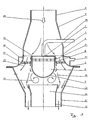
- FIGS. 1 and 2 show the fluidic switching element, consisting of an inflow 1 with conical extension 2 and cylindrical channel section 3, on which the Coanda tulip 5 and an outer outlet channel 11 with trap 13 connect.
- the inner outlet channel 12 with trap 14th is located downstream of the displacer 6.
- the displacement body 6 consists of a flat inflow surface 7 with outer tear-off edge 15, a cylindrical Sheath 8 and a trailer 9.
- the displacement body 6 is formed as a hollow body, the provided on the circumference of the lateral surface 8 with openings 21 is on the other hand connected to a control line 20 is.
- the exhaust gas mass flow 24 enters the fluidic switching element via the inflow line 1 a.
- the displacer 6 forces a ring flow 19, which at the outer tear-off edge 15 replaces.
- the ring flow 19 settles not by the cylindrical shell 8 of the displacer 6 on. It creates vortex area 18, which is the inner outlet channel 12 closes fluidically.
- the Ring flow 19 lays in the outer area to the Coanda tulip 5 and passes through the catching space 13 in the outer Outlet channel 11.
- the ring flow 19 settles after initial formation a separation vortex 16 immediately behind the tear-off 15 again to the cylindrical surface 8 of the displacement 6 on.
- the rotating vortex area 17 and the vortex area 18 adopt a stabilizing for the respective flow direction Function.
- control lines 20, 23 are either one or both control lines 20, 23 with the environment connected.
- the advantage of this solution is that cooler ambient air is sucked in and the outer Switching elements not the high exhaust gas temperatures of the main flow subject and no additional control medium needed becomes.
Landscapes
- Engineering & Computer Science (AREA)
- General Engineering & Computer Science (AREA)
- Mechanical Engineering (AREA)
- Chemical & Material Sciences (AREA)
- Combustion & Propulsion (AREA)
- Theoretical Computer Science (AREA)
- Physics & Mathematics (AREA)
- Fluid Mechanics (AREA)
- Multiple-Way Valves (AREA)
- Exhaust Silencers (AREA)
Description
- Zu große Spalte verursachen durch die radiale Bewegung
zwischen Welle und Lager Klappergeräusche.
Große Spalte setzen auch die Lebensdauer der Bauelemente herab. - Undichtigkeiten infolge großer Lagerspalte oder zwischen Verschlußorgan und Gehäuse erzeugen Pfeifgeräusche.
- Zu kleine Spalte im Lager führen infolge Verschmutzung oder unterschiedlicher Wärmeausdehnung von Welle und Lager zu Verklemmungen, die die Öffnungs- und Schließbewegungen des Verschlußorgans behindern.
- Die Anströmfläche kann mit geringer Krümmung konkav oder konvex geformt sein.
- Der Durchmesser der Anströmfläche kann wahlweise größer, kleiner oder gleich dem äußeren Umfang des Mantels gewählt werden.
- Der äußere Umfang der Anströmfläche kann eine Fase und/oder eine Kante oder einen Grenzschichtzaun aufweisen, scharfkantig oder abgerundet sein. Die Anordnung von Unterbrechungen, Zacken oder beliebige Unregelmäßigkeiten sind möglich.
- Der Mantel kann als Zylinder, Kegel, faßartig oder wellig ausgebildet sein.
- In Anströmfläche und/oder Mantel können Öffnungen vorgesehen sein, die den Innenraum des Verdrängerkörpers mit der Hauptströmung verbinden.
- Ggfs. vorgesehene Öffnungen im Verdrängerkörper und/oder an der Coanda-Tulpe können über Steuer- bzw. Verbindungsleitungen mit einem weiteren fluidhaltigen Druckniveau verbunden sein. Das zusätzliche Druckniveau kann insbesondere ein stromaufwärts oder stromabwärts vom Verdrängungskörper liegender Abschnitt der Abgasleitung selbst sein, oder ein Über- oder Unterdruckbehälter.
- Je nach Schaltaufgabe können die Verbindungsleitungen Strömungsführungen für Zusatzfluid zum gewünschten Zuführort oder Steuerleitungen sein, die insbesondere mit einem Ventil oder einem sonstigen Stellorgan versehen sein können.
- Der stromabwärts gerichtete Abschluß des Verdrängerkörpers kann entfallen (s.o.), oder als im wesentlichen ebene Scheibe, als Halbkugel oder als sonstiges geeignetes Strömungsprofil ausgebildet sein.
- Bei bestimmten geometrischen Anforderungen an den Einbauraum, kann das System aus Coanda-Tulpe, Verdrängerkörper Zuströmkanal und Auslaßkanälen von der koaxialen, axialsymmetrischen Form abweichen. In diesem Sinne kommt beispielsweise zur besonders flachen Ausführung des Schaltelements eine zweidimensionale Gestaltung mit einer ebenen Umströmung des Verdrängungskörpers in Betracht.
Entweder arbeitet das Schaltelement aus sich selbst heraus, passiv, autonom, oder der Schaltvorgang wird von außen durch einen aktiven, manuellen und/oder steuerungstechnischen Eingriff beliebig eingeleitet.
- Fig. 1
- ein fluidisches Schaltelement im ersten Schaltzustand und
- Fig. 2
- das fluidische Schaltelement gemäß Fig. 1 im zweiten Schaltzustand.
Claims (20)
- Fluidisches Schaltelement bestehend aus einem Zuströmkanal (1), einer Coanda-Tulpe (5), mindestens zwei Auslaßkanälen (11, 12), und einem im Bereich der Coanda-Tulpe (5) angeordneten Verdrängerkörper (6),
dadurch gekennzeichnet, daß der Verdrängerkörper (6) eine im wesentlichen ebene Anströmfläche (7) aufweist, an die sich in Strömungsrichtung ein Mantel (8) anschließt, wobei der Übergang von der Anströmfläche (7) zum Mantel (8) durch eine Abreißkante (15) definiert ist. - Fluidisches Schaltelement nach Anspruch 1,
dadurch gekennzeichnet, daß die Coanda-Tulpe (5) in der Schnittansicht als Bogenkontur, vorzugsweise als Viertelkreisbogen ausgeführt ist. - Fluidisches Schaltelement nach Anspruch 1 oder Anspruch 2,
dadurch gekennzeichnet, daß ein innerer Auslaßkanal (12) in einem äußeren Auslaßkanal (11) angeordnet ist, wobei jedem der beiden Auslaßkanäle (11, 12) ein Fangraum (13, 14) zugeordnet ist. - Fluidisches Schaltelement nach Anspruch 3,
dadurch gekennzeichnet, daß der Verdrängerkörper (6) räumlich umströmt ist und daß die Auslaßkanäle (11, 12) konzentrisch angeordnet und mit jeweils einem konischen oder zylindrischen Fangraum (13, 14) versehen sind. - Fluidisches Schaltelement nach Anspruch 3 oder Anspruch 4,
dadurch gekennzeichnet, daß der äußere Fangraum (13) stromabwärts am äußeren Umfang an die Coanda-Tulpe (5) anschließt. - Fluidisches Schaltelement nach einem der Ansprüche 3 bis 5,
dadurch gekennzeichnet, daß der innere Auslaßkanal (12) mit einem Abstand stromabwärts hinter dem Verdrängerkörper (6) angeordnet ist. - Fluidisches Schaltelement nach einem der Ansprüche 1 bis 6,
dadurch gekennzeichnet, daß zwischen Einlaßkanal (1) und Coanda-Tulpe (5) eine konische Erweiterung (2) und ein zylindrischer Kanalabschnitt (3) angeordnet sind. - Fluidisches Schaltelement nach einem der Ansprüche 1 bis 7,
dadurch gekennzeichnet, daß der Verdrängerkörper (6) an dem stromabwärtigen Ende einen kugelförmigen oder ebenen Nachlauf (9) aufweist. - Fluidisches Schaltelement nach einem der Ansprüche 1 bis 8,
dadurch gekennzeichnet, daß der Mantel (8) des Verdrängerkörpers (6) im wesentlichen zylindrisch ausgeführt und im Erweiterungsabschnitt der Coanda-Tulpe (5) angeordnet ist. - Fluidisches Schaltelement nach einem der Ansprüche 1 bis 9,
dadurch gekennzeichnet, daß die Coanda-Tulpe (5) mit Öffnungen (22), einer Ringleitung (10) und einer Verbindungsleitung (23) und/oder daß der Verdrängerkörper (6) mit Öffnungen (21) und einer Verbindungsleitung (20) versehen ist. - Fluidisches Schaltelement nach einem der Ansprüche 1 bis 10,
dadurch gekennzeichnet, daß der Verdrängerkörper (6) als Hohlkörper ausgebildet ist. - Fluidisches Schaltelement nach Anspruch 10 oder Anspruch 11,
dadurch gekennzeichnet, daß im Bereich eines zylindrisch ausgeführten Mantels (8) des Verdrängerkörpers Öffnungen (21) angeordnet sind. - Fluidisches Schaltelement nach Anspruch 10,
dadurch gekennzeichnet, daß die Coanda-Tulpe (5) über die als Steuerleitung ausgeführte Verbindungsleitung (23) und/oder der Verdrängerkörper (6) über die als Steuerleitung ausgeführte Verbindungsleitung (20) mit einem Druckpotential in Verbindung steht. - Fluidisches Schaltelement nach einem der Ansprüche 1 bis 13,
dadurch gekennzeichnet, daß die im wesentlichen ebene Anströmfläche (7) innerhalb der Coanda-Tulpe (5) angeordnet ist. - Fluidisches Schaltelement nach Anspruch 1,
dadurch gekennzeichnet, daß der Mantel (8) des Verdrängerkörpers (6) kegel- oder faßförmig ausgebildet ist. - Fluidisches Schaltelement nach einem der Ansprüche 1 bis 15,
dadurch gekennzeichnet, daß die Abreißkante (15) scharfkantig, gebrochen, abgerundet, mit Unterbrechungen ausgebildet oder mit einem Grenzschichtzaun oder unregelmäßigen Erhebungen und/oder Vertiefungen versehen ist. - Fluidisches Schaltelement nach einem der Ansprüche 1 bis 16,
dadurch gekennzeichnet, daß in der Anströmfläche (7) und/oder dem Mantel (8) des Verdrängungskörpers (6) Öffnungen angeordnet sind, die den Innenraum des Verdrängerkörpers mit der Hauptströmung verbinden. - Fluidisches Schaltelement nach Anspruch 13,
dadurch gekennzeichnet, daß das Druckpotential entweder ein stromauf- oder stromabwärtiger Abschnitt der Kanalführung selbst oder ein Über- oder Unterdruckbehälter ist. - Fluidisches Schaltelement nach Anspruch 13 oder Anspruch 18,
dadurch gekennzeichnet, daß die Steuerleitungen (20, 23) mit einem Ventil oder einem sonstigen Stellorgan versehen sind. - Fluidisches Schaltelement nach einem der Ansprüche 1 bis 19,
dadurch gekennzeichnet, daß Coanda-Tulpe (5), Verdrängerkörper (6), Zuströmkanal (1) und Auslaßkanäle (11, 12) nicht auf einer Achse liegen.
Applications Claiming Priority (3)
| Application Number | Priority Date | Filing Date | Title |
|---|---|---|---|
| DE2000100463 DE10000463A1 (de) | 2000-01-07 | 2000-01-07 | Fluidisches Schaltelement als Stoffstrom-Stellglied |
| DE10000463 | 2000-01-07 | ||
| PCT/EP2000/013255 WO2001051776A2 (de) | 2000-01-07 | 2000-12-23 | Fluidisches schaltelement |
Publications (2)
| Publication Number | Publication Date |
|---|---|
| EP1244868A2 EP1244868A2 (de) | 2002-10-02 |
| EP1244868B1 true EP1244868B1 (de) | 2005-11-09 |
Family
ID=7626948
Family Applications (1)
| Application Number | Title | Priority Date | Filing Date |
|---|---|---|---|
| EP00993784A Expired - Lifetime EP1244868B1 (de) | 2000-01-07 | 2000-12-23 | Fluidisches schaltelement |
Country Status (3)
| Country | Link |
|---|---|
| EP (1) | EP1244868B1 (de) |
| DE (2) | DE10000463A1 (de) |
| WO (1) | WO2001051776A2 (de) |
Families Citing this family (1)
| Publication number | Priority date | Publication date | Assignee | Title |
|---|---|---|---|---|
| WO2016150771A1 (en) | 2015-03-20 | 2016-09-29 | Novozymes A/S | Droplet-based selection by injection |
Family Cites Families (18)
| Publication number | Priority date | Publication date | Assignee | Title |
|---|---|---|---|---|
| DD153419A1 (de) * | 1980-10-06 | 1982-01-06 | Klaus Thomas | Monostabiles wandstrahlelement |
| US5311329A (en) | 1991-08-28 | 1994-05-10 | Silicon Graphics, Inc. | Digital filtering for lenticular printing |
| US5466298A (en) | 1993-10-01 | 1995-11-14 | James River Paper Company, Inc. | Web cleaning method |
| US5801343A (en) | 1993-11-09 | 1998-09-01 | Futaba Industrial Co., Ltd. | Muffler for internal combustion engine |
| US5435489A (en) | 1994-01-13 | 1995-07-25 | Bell Helicopter Textron Inc. | Engine exhaust gas deflection system |
| US5614699A (en) | 1994-05-09 | 1997-03-25 | Nissan Motor Co., Ltd. | Automobile exhaust noise suppressor |
| FR2724217B1 (fr) | 1994-09-07 | 1996-10-25 | Air Liquide | Dispositif d'etalement d'une flamme par effet coanda et four comportant ce dispositif |
| DE69531286T2 (de) | 1995-02-24 | 2004-01-29 | Calsonic Kansei Corp | Schalldämpferkontrollgerät zur Verwendung in einem steuerbaren Abgassystem einer Brennkraftmaschine |
| US5758823A (en) | 1995-06-12 | 1998-06-02 | Georgia Tech Research Corporation | Synthetic jet actuator and applications thereof |
| DE19540716C1 (de) | 1995-11-02 | 1997-04-17 | Gillet Heinrich Gmbh | Schalldämpfer mit variabler Dämpfungscharakteristik |
| DE19709432A1 (de) * | 1996-03-13 | 1997-10-30 | Volkswagen Ag | Vorrichtung zur Behandlung von Abgasen aus Brennkraftmaschinen |
| DE19729666C2 (de) | 1996-07-20 | 2002-01-17 | Gillet Heinrich Gmbh | Schalldämpfer mit variabler Dämpfungscharakteristik |
| DE19637078A1 (de) | 1996-09-12 | 1998-03-19 | Pierburg Ag | Elektromagnetisches Steuerventil für Abgasrückführung |
| DE19715939C1 (de) | 1997-04-17 | 1998-12-03 | Daimler Benz Ag | Abgasanlage für eine Brennkraftmaschine |
| DE19817340A1 (de) | 1997-05-02 | 1998-11-05 | Volkswagen Ag | Verfahren zur Erwärmung der Kühlflüssigkeit bei einem Kraftfahrzeug und Abgasanlage |
| DE19729563A1 (de) * | 1997-07-10 | 1999-01-14 | Volkswagen Ag | Fluidisches Verteilerventil |
| JP3017964B2 (ja) | 1997-09-12 | 2000-03-13 | 株式会社三五 | 消音器 |
| DE19817391A1 (de) | 1998-04-20 | 1999-10-21 | Daimler Chrysler Ag | Zündkerze für eine Brennkraftmaschine bzw. Sensorelement für Entflammungs- und Verbrennungsvorgang |
-
2000
- 2000-01-07 DE DE2000100463 patent/DE10000463A1/de not_active Withdrawn
- 2000-12-23 DE DE50011590T patent/DE50011590D1/de not_active Expired - Fee Related
- 2000-12-23 EP EP00993784A patent/EP1244868B1/de not_active Expired - Lifetime
- 2000-12-23 WO PCT/EP2000/013255 patent/WO2001051776A2/de not_active Ceased
Also Published As
| Publication number | Publication date |
|---|---|
| DE50011590D1 (de) | 2005-12-15 |
| DE10000463A1 (de) | 2001-07-26 |
| EP1244868A2 (de) | 2002-10-02 |
| WO2001051776A2 (de) | 2001-07-19 |
| WO2001051776A3 (de) | 2001-12-20 |
Similar Documents
| Publication | Publication Date | Title |
|---|---|---|
| WO1996021815A1 (de) | Absperr- oder drosselventil mit drehbarer ventilklappe | |
| EP1614945A1 (de) | Rückschlagventil | |
| WO2013079692A1 (de) | Kugelventil mit externer dichtungsanordnung, insbesondere für den einsatz in kraftfahrzeugkältemittelkreisläufen | |
| DE102005042679A1 (de) | Bypassventil für Verbrennungskraftmaschinen | |
| DE102008050252B4 (de) | Ventilvorrichtung für Brennkraftmaschinen, insbesondere Sekundärluftventil | |
| EP1747369B1 (de) | Regelbare zweiwegeventilvorrichtung | |
| EP2623764B1 (de) | Abgaswegeventil | |
| EP2942500A1 (de) | Abgaswärmetauscher mit bypassrohr | |
| EP2436960B1 (de) | Dichtbuchsenanordnung und hydraulisches Gerät | |
| DE202019101676U1 (de) | Ventil für eine Abgasleitung | |
| EP3189289A1 (de) | Elektromagnetisch betätigbares expansionsventil | |
| DE2448383C2 (de) | Temperaturgesteuertes Ventil | |
| DE3831687A1 (de) | Radialturbine mit im stroemungsquerschnitt veraenderbarem spiralgehaeuse | |
| EP1789712B1 (de) | Axial- und radialspiel sowie winkelausgleich tolerierende rohrverbindung | |
| EP3705696B1 (de) | Klappenvorrichtung für eine verbrennungskraftmaschine | |
| EP2194300B1 (de) | Rückschlagventil für eine hydraulische Servolenkung | |
| DE202018105534U1 (de) | Ventil | |
| DE102020100952B4 (de) | Ventilvorrichtung für eine Verbrennungskraftmaschine | |
| EP1244867B1 (de) | Strömungsschalter | |
| EP1072784B1 (de) | Steuerventil zur Abgasrückführung | |
| EP1244868A2 (de) | Fluidisches schaltelement | |
| DE102004049253B4 (de) | Thermostatventil | |
| DE102016104183A1 (de) | Dichtungsanordnung für ein Drehschieberventil | |
| EP3405655B1 (de) | Turbolader mit schieber zur flutenverbindung | |
| DE102015111252B4 (de) | Ventil für einen Abgasstrang einer Brennkraftmaschine |
Legal Events
| Date | Code | Title | Description |
|---|---|---|---|
| PUAI | Public reference made under article 153(3) epc to a published international application that has entered the european phase |
Free format text: ORIGINAL CODE: 0009012 |
|
| 17P | Request for examination filed |
Effective date: 20020625 |
|
| AK | Designated contracting states |
Kind code of ref document: A2 Designated state(s): AT BE CH CY DE DK ES FI FR GB GR IE IT LI LU MC NL PT SE TR |
|
| RBV | Designated contracting states (corrected) |
Designated state(s): AT BE CH DE FR IT LI |
|
| GRAP | Despatch of communication of intention to grant a patent |
Free format text: ORIGINAL CODE: EPIDOSNIGR1 |
|
| GRAJ | Information related to disapproval of communication of intention to grant by the applicant or resumption of examination proceedings by the epo deleted |
Free format text: ORIGINAL CODE: EPIDOSDIGR1 |
|
| GRAP | Despatch of communication of intention to grant a patent |
Free format text: ORIGINAL CODE: EPIDOSNIGR1 |
|
| RBV | Designated contracting states (corrected) |
Designated state(s): DE FR IT |
|
| GRAS | Grant fee paid |
Free format text: ORIGINAL CODE: EPIDOSNIGR3 |
|
| GRAA | (expected) grant |
Free format text: ORIGINAL CODE: 0009210 |
|
| RIN1 | Information on inventor provided before grant (corrected) |
Inventor name: REGENOLD, KLAUS Inventor name: ELFINGER, GERHARD, DR. Inventor name: HAHNL, WOLFGANG, DR. Inventor name: BIRKE, MAREK Inventor name: KLEMENT, JUERGEN Inventor name: OLESEN, MARK, DR. Inventor name: MAYR, ANDREAS |
|
| RAP1 | Party data changed (applicant data changed or rights of an application transferred) |
Owner name: ARVINMERITOR EMISSIONS TECHNOLOGIES GMBH |
|
| AK | Designated contracting states |
Kind code of ref document: B1 Designated state(s): DE FR IT |
|
| PG25 | Lapsed in a contracting state [announced via postgrant information from national office to epo] |
Ref country code: IT Free format text: LAPSE BECAUSE OF FAILURE TO SUBMIT A TRANSLATION OF THE DESCRIPTION OR TO PAY THE FEE WITHIN THE PRESCRIBED TIME-LIMIT;WARNING: LAPSES OF ITALIAN PATENTS WITH EFFECTIVE DATE BEFORE 2007 MAY HAVE OCCURRED AT ANY TIME BEFORE 2007. THE CORRECT EFFECTIVE DATE MAY BE DIFFERENT FROM THE ONE RECORDED. Effective date: 20051109 |
|
| REF | Corresponds to: |
Ref document number: 50011590 Country of ref document: DE Date of ref document: 20051215 Kind code of ref document: P |
|
| PLBE | No opposition filed within time limit |
Free format text: ORIGINAL CODE: 0009261 |
|
| STAA | Information on the status of an ep patent application or granted ep patent |
Free format text: STATUS: NO OPPOSITION FILED WITHIN TIME LIMIT |
|
| 26N | No opposition filed |
Effective date: 20060810 |
|
| EN | Fr: translation not filed | ||
| PG25 | Lapsed in a contracting state [announced via postgrant information from national office to epo] |
Ref country code: FR Free format text: LAPSE BECAUSE OF FAILURE TO SUBMIT A TRANSLATION OF THE DESCRIPTION OR TO PAY THE FEE WITHIN THE PRESCRIBED TIME-LIMIT Effective date: 20061229 |
|
| PG25 | Lapsed in a contracting state [announced via postgrant information from national office to epo] |
Ref country code: FR Free format text: LAPSE BECAUSE OF FAILURE TO SUBMIT A TRANSLATION OF THE DESCRIPTION OR TO PAY THE FEE WITHIN THE PRESCRIBED TIME-LIMIT Effective date: 20051231 |
|
| PGFP | Annual fee paid to national office [announced via postgrant information from national office to epo] |
Ref country code: DE Payment date: 20080630 Year of fee payment: 8 |
|
| PG25 | Lapsed in a contracting state [announced via postgrant information from national office to epo] |
Ref country code: FR Free format text: LAPSE BECAUSE OF FAILURE TO SUBMIT A TRANSLATION OF THE DESCRIPTION OR TO PAY THE FEE WITHIN THE PRESCRIBED TIME-LIMIT Effective date: 20051109 |
|
| PG25 | Lapsed in a contracting state [announced via postgrant information from national office to epo] |
Ref country code: DE Free format text: LAPSE BECAUSE OF NON-PAYMENT OF DUE FEES Effective date: 20090701 |