EP1243769A1 - R gulateur de rapport air-carburant de moteurs thermiques - Google Patents
R gulateur de rapport air-carburant de moteurs thermiques Download PDFInfo
- Publication number
- EP1243769A1 EP1243769A1 EP00987695A EP00987695A EP1243769A1 EP 1243769 A1 EP1243769 A1 EP 1243769A1 EP 00987695 A EP00987695 A EP 00987695A EP 00987695 A EP00987695 A EP 00987695A EP 1243769 A1 EP1243769 A1 EP 1243769A1
- Authority
- EP
- European Patent Office
- Prior art keywords
- fuel ratio
- value
- air
- catalytic converter
- exhaust gas
- Prior art date
- Legal status (The legal status is an assumption and is not a legal conclusion. Google has not performed a legal analysis and makes no representation as to the accuracy of the status listed.)
- Granted
Links
Images


Classifications
-
- F—MECHANICAL ENGINEERING; LIGHTING; HEATING; WEAPONS; BLASTING
- F02—COMBUSTION ENGINES; HOT-GAS OR COMBUSTION-PRODUCT ENGINE PLANTS
- F02D—CONTROLLING COMBUSTION ENGINES
- F02D41/00—Electrical control of supply of combustible mixture or its constituents
- F02D41/02—Circuit arrangements for generating control signals
- F02D41/14—Introducing closed-loop corrections
- F02D41/1438—Introducing closed-loop corrections using means for determining characteristics of the combustion gases; Sensors therefor
- F02D41/1439—Introducing closed-loop corrections using means for determining characteristics of the combustion gases; Sensors therefor characterised by the position of the sensor
- F02D41/1441—Plural sensors
-
- F—MECHANICAL ENGINEERING; LIGHTING; HEATING; WEAPONS; BLASTING
- F02—COMBUSTION ENGINES; HOT-GAS OR COMBUSTION-PRODUCT ENGINE PLANTS
- F02D—CONTROLLING COMBUSTION ENGINES
- F02D41/00—Electrical control of supply of combustible mixture or its constituents
- F02D41/02—Circuit arrangements for generating control signals
- F02D41/14—Introducing closed-loop corrections
-
- F—MECHANICAL ENGINEERING; LIGHTING; HEATING; WEAPONS; BLASTING
- F01—MACHINES OR ENGINES IN GENERAL; ENGINE PLANTS IN GENERAL; STEAM ENGINES
- F01N—GAS-FLOW SILENCERS OR EXHAUST APPARATUS FOR MACHINES OR ENGINES IN GENERAL; GAS-FLOW SILENCERS OR EXHAUST APPARATUS FOR INTERNAL COMBUSTION ENGINES
- F01N11/00—Monitoring or diagnostic devices for exhaust-gas treatment apparatus, e.g. for catalytic activity
- F01N11/007—Monitoring or diagnostic devices for exhaust-gas treatment apparatus, e.g. for catalytic activity the diagnostic devices measuring oxygen or air concentration downstream of the exhaust apparatus
-
- F—MECHANICAL ENGINEERING; LIGHTING; HEATING; WEAPONS; BLASTING
- F02—COMBUSTION ENGINES; HOT-GAS OR COMBUSTION-PRODUCT ENGINE PLANTS
- F02D—CONTROLLING COMBUSTION ENGINES
- F02D41/00—Electrical control of supply of combustible mixture or its constituents
- F02D41/02—Circuit arrangements for generating control signals
- F02D41/021—Introducing corrections for particular conditions exterior to the engine
- F02D41/0235—Introducing corrections for particular conditions exterior to the engine in relation with the state of the exhaust gas treating apparatus
-
- F—MECHANICAL ENGINEERING; LIGHTING; HEATING; WEAPONS; BLASTING
- F02—COMBUSTION ENGINES; HOT-GAS OR COMBUSTION-PRODUCT ENGINE PLANTS
- F02D—CONTROLLING COMBUSTION ENGINES
- F02D41/00—Electrical control of supply of combustible mixture or its constituents
- F02D41/02—Circuit arrangements for generating control signals
- F02D41/14—Introducing closed-loop corrections
- F02D41/1401—Introducing closed-loop corrections characterised by the control or regulation method
- F02D41/1403—Sliding mode control
-
- F—MECHANICAL ENGINEERING; LIGHTING; HEATING; WEAPONS; BLASTING
- F01—MACHINES OR ENGINES IN GENERAL; ENGINE PLANTS IN GENERAL; STEAM ENGINES
- F01N—GAS-FLOW SILENCERS OR EXHAUST APPARATUS FOR MACHINES OR ENGINES IN GENERAL; GAS-FLOW SILENCERS OR EXHAUST APPARATUS FOR INTERNAL COMBUSTION ENGINES
- F01N2550/00—Monitoring or diagnosing the deterioration of exhaust systems
- F01N2550/02—Catalytic activity of catalytic converters
-
- F—MECHANICAL ENGINEERING; LIGHTING; HEATING; WEAPONS; BLASTING
- F02—COMBUSTION ENGINES; HOT-GAS OR COMBUSTION-PRODUCT ENGINE PLANTS
- F02D—CONTROLLING COMBUSTION ENGINES
- F02D41/00—Electrical control of supply of combustible mixture or its constituents
- F02D41/02—Circuit arrangements for generating control signals
- F02D41/14—Introducing closed-loop corrections
- F02D41/1401—Introducing closed-loop corrections characterised by the control or regulation method
- F02D2041/1409—Introducing closed-loop corrections characterised by the control or regulation method using at least a proportional, integral or derivative controller
-
- F—MECHANICAL ENGINEERING; LIGHTING; HEATING; WEAPONS; BLASTING
- F02—COMBUSTION ENGINES; HOT-GAS OR COMBUSTION-PRODUCT ENGINE PLANTS
- F02D—CONTROLLING COMBUSTION ENGINES
- F02D41/00—Electrical control of supply of combustible mixture or its constituents
- F02D41/02—Circuit arrangements for generating control signals
- F02D41/14—Introducing closed-loop corrections
- F02D41/1401—Introducing closed-loop corrections characterised by the control or regulation method
- F02D2041/1413—Controller structures or design
- F02D2041/1415—Controller structures or design using a state feedback or a state space representation
- F02D2041/1416—Observer
-
- F—MECHANICAL ENGINEERING; LIGHTING; HEATING; WEAPONS; BLASTING
- F02—COMBUSTION ENGINES; HOT-GAS OR COMBUSTION-PRODUCT ENGINE PLANTS
- F02D—CONTROLLING COMBUSTION ENGINES
- F02D41/00—Electrical control of supply of combustible mixture or its constituents
- F02D41/02—Circuit arrangements for generating control signals
- F02D41/14—Introducing closed-loop corrections
- F02D41/1401—Introducing closed-loop corrections characterised by the control or regulation method
- F02D2041/1413—Controller structures or design
- F02D2041/1418—Several control loops, either as alternatives or simultaneous
-
- F—MECHANICAL ENGINEERING; LIGHTING; HEATING; WEAPONS; BLASTING
- F02—COMBUSTION ENGINES; HOT-GAS OR COMBUSTION-PRODUCT ENGINE PLANTS
- F02D—CONTROLLING COMBUSTION ENGINES
- F02D41/00—Electrical control of supply of combustible mixture or its constituents
- F02D41/02—Circuit arrangements for generating control signals
- F02D41/14—Introducing closed-loop corrections
- F02D41/1401—Introducing closed-loop corrections characterised by the control or regulation method
- F02D2041/1413—Controller structures or design
- F02D2041/142—Controller structures or design using different types of control law in combination, e.g. adaptive combined with PID and sliding mode
-
- F—MECHANICAL ENGINEERING; LIGHTING; HEATING; WEAPONS; BLASTING
- F02—COMBUSTION ENGINES; HOT-GAS OR COMBUSTION-PRODUCT ENGINE PLANTS
- F02D—CONTROLLING COMBUSTION ENGINES
- F02D41/00—Electrical control of supply of combustible mixture or its constituents
- F02D41/02—Circuit arrangements for generating control signals
- F02D41/14—Introducing closed-loop corrections
- F02D41/1401—Introducing closed-loop corrections characterised by the control or regulation method
- F02D2041/1413—Controller structures or design
- F02D2041/1431—Controller structures or design the system including an input-output delay
-
- F—MECHANICAL ENGINEERING; LIGHTING; HEATING; WEAPONS; BLASTING
- F02—COMBUSTION ENGINES; HOT-GAS OR COMBUSTION-PRODUCT ENGINE PLANTS
- F02D—CONTROLLING COMBUSTION ENGINES
- F02D41/00—Electrical control of supply of combustible mixture or its constituents
- F02D41/02—Circuit arrangements for generating control signals
- F02D41/14—Introducing closed-loop corrections
- F02D41/1401—Introducing closed-loop corrections characterised by the control or regulation method
- F02D2041/1413—Controller structures or design
- F02D2041/1432—Controller structures or design the system including a filter, e.g. a low pass or high pass filter
-
- F—MECHANICAL ENGINEERING; LIGHTING; HEATING; WEAPONS; BLASTING
- F02—COMBUSTION ENGINES; HOT-GAS OR COMBUSTION-PRODUCT ENGINE PLANTS
- F02D—CONTROLLING COMBUSTION ENGINES
- F02D41/00—Electrical control of supply of combustible mixture or its constituents
- F02D41/02—Circuit arrangements for generating control signals
- F02D41/14—Introducing closed-loop corrections
- F02D41/1401—Introducing closed-loop corrections characterised by the control or regulation method
- F02D2041/1433—Introducing closed-loop corrections characterised by the control or regulation method using a model or simulation of the system
-
- F—MECHANICAL ENGINEERING; LIGHTING; HEATING; WEAPONS; BLASTING
- F02—COMBUSTION ENGINES; HOT-GAS OR COMBUSTION-PRODUCT ENGINE PLANTS
- F02D—CONTROLLING COMBUSTION ENGINES
- F02D41/00—Electrical control of supply of combustible mixture or its constituents
- F02D41/02—Circuit arrangements for generating control signals
- F02D41/14—Introducing closed-loop corrections
- F02D41/1401—Introducing closed-loop corrections characterised by the control or regulation method
- F02D41/1402—Adaptive control
-
- F—MECHANICAL ENGINEERING; LIGHTING; HEATING; WEAPONS; BLASTING
- F02—COMBUSTION ENGINES; HOT-GAS OR COMBUSTION-PRODUCT ENGINE PLANTS
- F02D—CONTROLLING COMBUSTION ENGINES
- F02D41/00—Electrical control of supply of combustible mixture or its constituents
- F02D41/02—Circuit arrangements for generating control signals
- F02D41/14—Introducing closed-loop corrections
- F02D41/1438—Introducing closed-loop corrections using means for determining characteristics of the combustion gases; Sensors therefor
- F02D41/1444—Introducing closed-loop corrections using means for determining characteristics of the combustion gases; Sensors therefor characterised by the characteristics of the combustion gases
- F02D41/1454—Introducing closed-loop corrections using means for determining characteristics of the combustion gases; Sensors therefor characterised by the characteristics of the combustion gases the characteristics being an oxygen content or concentration or the air-fuel ratio
- F02D41/1456—Introducing closed-loop corrections using means for determining characteristics of the combustion gases; Sensors therefor characterised by the characteristics of the combustion gases the characteristics being an oxygen content or concentration or the air-fuel ratio with sensor output signal being linear or quasi-linear with the concentration of oxygen
-
- Y—GENERAL TAGGING OF NEW TECHNOLOGICAL DEVELOPMENTS; GENERAL TAGGING OF CROSS-SECTIONAL TECHNOLOGIES SPANNING OVER SEVERAL SECTIONS OF THE IPC; TECHNICAL SUBJECTS COVERED BY FORMER USPC CROSS-REFERENCE ART COLLECTIONS [XRACs] AND DIGESTS
- Y02—TECHNOLOGIES OR APPLICATIONS FOR MITIGATION OR ADAPTATION AGAINST CLIMATE CHANGE
- Y02T—CLIMATE CHANGE MITIGATION TECHNOLOGIES RELATED TO TRANSPORTATION
- Y02T10/00—Road transport of goods or passengers
- Y02T10/10—Internal combustion engine [ICE] based vehicles
- Y02T10/40—Engine management systems
Definitions
- the present invention relates to an apparatus for controlling the air-fuel ratio of an internal combustion engine, and more particularly to an air-fuel ratio control apparatus which is capable of evaluating the deteriorated state of a catalytic converter for purifying exhaust gases.
- the disclosed techniques are based on the fact that when the air-fuel ratio of an air-fuel mixture to be combusted by an internal combustion engine is changed from a leaner value to a richer value or from a richer value to a leaner value, the outputs from oxygen concentration sensors that are positioned respectively upstream and downstream of a catalytic converter combined with the internal combustion engine are inverted. More specifically, under certain operating conditions of the internal combustion engine, i.e., when the power output of the internal combustion engine is increased or the fuel supplied to the internal combustion engine is cut off as disclosed in Japanese patent publication No. 2,526,640 or when certain conditions are satisfied, e.g., the load and rotational speed of the internal combustion engine are in predetermined ranges as disclosed in Japanese laid-open patent publication No.
- the air-fuel ratio is positively changed from a leaner value to a richer value or from a richer value to a leaner value.
- the time consumed after the output of the upstream oxygen concentration sensor is inverted until the output of the downstream oxvgen concentration sensor is inverted, and the period at which output of the downstream oxygen concentration sensor is inverted are measured, and the deteriorated state of the catalytic converter is evaluated based on the measured values.
- the air-fuel ratio is feedback-controlled depending on the inversion of the outputs from the oxygen concentration sensors in order to keep the air-fuel ratio of the internal combustion engine in the vicinity of a stoichiometric air-fuel ratio, for thereby allowing the catalytic converter to keep an appropriate purifying capability.
- an exhaust gas sensor for detecting the concentration of a certain component, e.g., oxygen, of exhaust gases is positioned downstream of the catalytic converter, and the air-fuel ratio of an air-fuel mixture to be combusted by an internal combustion engine is manipulated in order to converge the output of the exhaust gas sensor to a predetermined target value.
- a certain component e.g., oxygen
- a target value (target air-fuel ratio) for the air-fuel ratio of the exhaust gases that enter the catalytic converter, or specifically the air-fuel ratio recognized from the oxygen concentration of the exhaust gases is successively calculated according to a sliding mode control process.
- the air-fuel ratio of the air-fuel mixture to be combusted by an internal combustion engine is then manipulated depending on the target air-fuel ratio to achieve the appropriate purifying capability of the catalytic converter.
- the above proposed technique is capable of stably keeping the appropriate purifying capability of the catalytic converter by controlling the air-fuel ratio as described above, it is desirable to be able to evaluate the deteriorated state of the catalytic converter while performing the above air-fuel control process.
- an apparatus for controlling the air-fuel ratio of an internal combustion engine comprising an exhaust gas sensor disposed downstream of a catalytic converter which is disposed in an exhaust passage of an internal combustion engine, for detecting the concentration of a particular component of a exhaust gas emitted from the internal combustion engine and having passed through the catalytic converter, air-fuel ratio manipulated variable generating means for sequentially generating a manipulated variable to determine the air-fuel ratio of the exhaust gas entering the catalytic converter to converge an output of the exhaust gas sensor to a predetermined target value, air-fuel ratio manipulating means for manipulating the air-fuel ratio of an air-fuel mixture to be combusted in the internal combustion engine depending on the manipulated variable, and deteriorated state evaluating means for sequentially determining the value of a deterioration evaluating linear function from time-series data of the output of the exhaust gas sensor, the deterioration evaluating linear function having variable components represented by the time-series data of the output of the output of the
- the inventors of the present invention have found that while a manipulated variable for the air-fuel ratio (e.g., a target value for the air-fuel ratio) of the exhaust gas entering the catalytic converter to converge the output of the exhaust gas sensor downstream of the catalytic converter to a given target value is being sequentially generated and the air-fuel ratio of the air-fuel mixture is being manipulated depending on the manipulated variable, when an appropriate linear function whose variable components are represented by time-series data of the output of the exhaust gas sensor, i.e., a linear function expressed as a linear coupling of the time-series data of the output of the exhaust gas sensor, is determined from the time-series data of the output of the exhaust gas sensor, the value of the linear function has a tendency to exhibit a characteristic correlation between itself and the degree to which the deterioration of the catalytic converter progresses.
- a manipulated variable for the air-fuel ratio e.g., a target value for the air-fuel ratio
- the value of the linear function tends to be accumulated in the vicinity of a certain value.
- the value of the linear function tends to go away from the certain value. Stated otherwise, as the deterioration of the catalytic converter progresses, the degree to which the value of the linear function varies becomes larger.
- the deteriorated state evaluating means employs the above linear function as the deterioration evaluating linear function, and sequentially determines the value of the deterioration evaluating linear function from the time-series data of the output of the exhaust gas sensor.
- the deteriorated state evaluating means determines the deteriorated state of the catalytic converter based on the value of the deterioration evaluating linear function.
- the value of the deterioration evaluating linear function as a basis for evaluating the deteriorated state of the catalytic converter is determined from time-series data of the output of the exhaust gas sensor while the air-fuel ratio manipulating means is manipulating the air-fuel ratio of the air-fuel mixture depending on the manipulated variable that is generated by the air-fuel ratio manipulated variable generating means in order to converge the output of the exhaust gas sensor to the target value. Therefore, the value of the deterioration evaluating linear function is obtained while the air-fuel ratio is being manipulated to maintain a desired purifying capability of the catalytic converter.
- the deteriorated state of the catalytic converter can be evaluated while maintaining the desired purifying capability of the catalytic converter, by evaluating the deteriorated state of the catalytic converter based on the value of the deterioration evaluating linear function.
- the above tendency of the value of the deterioration evaluating linear function depending on the degree to which the deterioration of the catalytic converter progresses is likely to be clear when the manipulated variable is generated by the air-fuel ratio manipulated variable generating means according to a sliding mode control process as one feedback control process.
- the air-fuel ratio manipulated variable generating means comprises means for generating the manipulated variable according to the sliding mode control process
- the deterioration evaluating linear function which is highly correlated to the deteriorated state of the catalytic converter is closely related to a switching function used in the sliding mode control process. Therefore, a linear function determined depending on the switching function is preferably used as the deterioration evaluating linear function.
- the sliding mode control process used by the air-fuel ratio manipulated variable generating means employs a linear function whose variable components are represented by time-series data of the difference between the output of the exhaust gas sensor and the target value, for example, as the switching function. If this switching function is used in the sliding mode control process, then the deterioration evaluating linear function preferably comprises a linear function which has coefficients of variable components that are identical to coefficients of the variable components of the switching function.
- the linear function may be the switching function itself for the sliding mode control process.
- the correlation between the value of the deterioration evaluating linear function and the deteriorated state of the catalytic converter is manifested, allowing the deteriorated state of the catalytic converter to be evaluated appropriately based on the value of the deterioration evaluating linear function.
- the deteriorated state evaluating means preferably comprises means for determining data representing the degree to which time-series data of the value of the deterioration evaluating linear function vary, as a deterioration evaluating parameter from the time-series data of the value of the deterioration evaluating linear function, and evaluating the deteriorated state of the catalytic converter based on the value of the determined deterioration evaluating parameter.
- the value of the deterioration evaluating linear function is liable to change away from a certain value, resulting in a large variation of the value of the deterioration evaluating linear function.
- the data representing the degree to which the time-series data of the value of the deterioration evaluating linear function vary is used as the deterioration evaluating parameter, and the deterioration evaluating parameter is determined from the time-series data of the value of the deterioration evaluating linear function.
- the correlation between its value and the deteriorated state of the catalytic converter is made clear, making it possible to evaluate the deteriorated state of the catalytic converter more appropriately based on the value of the deterioration evaluating parameter.
- the deterioration evaluating parameter may comprise the square or absolute value of the difference between the value of the deterioration evaluating linear function and a predetermined value.
- the deterioration evaluating parameter is determined by effecting a low-pass filtering process on the square or absolute value of the difference between each of the time-series data of the value of the deterioration evaluating linear function and a predetermined value as a central value of the value of the deterioration evaluating linear function.
- the value of the deterioration evaluating parameter is adequate as a value representing the degree to which the value of the deterioration evaluating linear function varies.
- the value of the deterioration evaluating parameter increases monotonously, clearly indicating a correlation between itself and the deteriorated state of the catalytic converter. Therefore, it is possible to evaluate the deteriorated state of the catalytic converter with high reliability based on the value of the deterioration evaluating parameter.
- the low-pass filtering process preferably comprises a filtering process according to a sequential statistic algorithm.
- the deterioration evaluating parameter can be stored in a reduced memory capacity without the need for a memory for storing many data of the difference and its square or absolute value.
- the sequential statistic algorithm may preferably comprise a method of least squares, a method of weighted least squares, a degressive gain method, a fixed gain method, etc.
- the deterioration evaluating parameter increases monotonously as the deterioration of the catalytic converter progresses. Therefore, the deteriorated state evaluating means may comprise means for comparing the deterioration evaluating parameter with a predetermined threshold to determine whether the catalytic converter is deteriorated to an extent corresponding to the threshold or not.
- the deteriorated state evaluating means may comprise means for determining whether the deteriorated state of the catalytic converter is to be evaluated or not depending on a change in the rate of flow of the exhaust gas entering the catalytic converter.
- the deteriorated state evaluating means may comprise means for failing to evaluate the deteriorated state of the catalytic converter if the rate of flow of the exhaust gas entering the catalytic converter is maintained at a substantially constant level, and evaluating the deteriorated state of the catalytic converter if the rate of flow of the exhaust gas entering the catalytic converter is not maintained at the substantially constant level.
- the evaluation of the deteriorated state of the catalytic converter is made highly reliable.
- the deteriorated state evaluating means may comprise means for failing to determine the deterioration evaluating parameter if the rate of flow of the exhaust gas entering the catalytic converter is maintained at a substantially constant level, and determining the deterioration evaluating parameter if the rate of flow of the exhaust gas entering the catalytic converter is not maintained at the substantially constant level.
- the air-fuel ratio manipulated variable generating means may comprise estimating means for sequentially determining data representing an estimated value of the output of the exhaust gas sensor after a dead time of a system ranging from a position upstream of the catalytic converter to the exhaust gas sensor, and means for generating the manipulated variable using the data determined by the estimating means.
- the air-fuel ratio manipulated variable generating means may comprise estimating means for sequentially determining data representing an estimated value of the output of the exhaust gas sensor after a total data time which is the sum of a dead time of a system ranging from a position upstream of the catalytic converter to the exhaust gas sensor and a dead time of a system comprising the air-fuel ratio manipulating system and the internal combustion engine, and means for generating the manipulated variable using the data determined by the estimating means.
- the system ranging from the position upstream of the catalytic converter to the exhaust gas sensor i.e., a system for generating the output of the exhaust gas sensor from the air-fuel ratio of the exhaust gas determined by the manipulated variable (hereinafter referred to as "object exhaust system”), generally has a relatively long dead time due to the catalytic converter included in the object exhaust system.
- the system comprising the air-fuel ratio manipulating system and the internal combustion engine i.e., a system for generating the air-fuel ratio of the exhaust gas entering the catalytic converter from the manipulated variable (hereinafter referred to as "air-fuel ratio manipulating system”
- air-fuel ratio manipulating system also has a relatively long dead time. These dead times should preferably be compensated for as they may possibly adversely affect the process of converting the output of the exhaust gas sensor to the target value.
- the estimating means determines data representing the estimated value of the output of the exhaust gas sensor after the dead time of the object exhaust system, or data representing the estimated value of the output of the exhaust gas sensor after the total data time which is the sum of the above dead time and the dead time of the air-fuel ratio manipulating system, and the manipulated variable is generated using the data determined by the estimating means.
- the process of converting the output of the exhaust gas sensor to the target value can well be performed.
- the deteriorated state of the catalytic converter can be evaluated while well maintaining the desired purifying capability or performance of the catalytic converter.
- the air-fuel ratio manipulated variable generating means comprises means for generating the manipulated variable to converge the estimated value of the output of the exhaust gas sensor represented by the data determined by the estimating means to the target value, according to the sliding mode control process.
- the process of converting the output of the exhaust gas sensor to the target value is thus performed highly stably, and hence the desired purifying capability of the catalytic converter can be maintained stably.
- the data representing the estimated value of the output of the exhaust gas sensor can be generated using the output of the exhaust gas sensor and the manipulated variable generated in the past by the air-fuel ratio manipulated variable generating means or the detected value of the air-fuel ratio of the exhaust gas upstream of the catalytic converter which depends on the manipulated variable.
- the sliding mode control process comprises an adaptive sliding mode control process.
- the adaptive sliding mode control process is a combination of an ordinary sliding mode control process and a control law referred to as an adaptive law (adaptive algorithm).
- an adaptive law adaptive algorithm
- the manipulated variable is generated according to the adaptive sliding mode control process, the reliability of the manipulated variable is increased, allowing the output of the exhaust gas sensor to be converged to the target value with a quick response.
- the effect of a simple disturbance other than the deteriorated state of the catalytic converter on the value of the deterioration evaluating linear function determined depending on the switching function for the sliding mode control process is suppressed. Consequently, the reliability of the evaluation of the deteriorated state of the catalytic converter based on the deterioration evaluating parameter which represents the degree to which the value of the deterioration evaluating linear function varies is increased.
- the manipulated variable generated by the air-fuel ratio manipulated variable generating means comprises a target air-fuel ratio for the exhaust gas entering the catalytic converter, and the apparatus further comprises an air-fuel ratio sensor disposed upstream of the catalytic converter for detecting the air-fuel ratio of the exhaust gas entering the catalytic converter, the air-fuel ratio manipulating means comprising means for manipulating the air-fuel ratio of the air-fuel mixture according to a feedback control process to converge the output of the air-fuel ratio sensor to the target air-fuel ratio.
- the output of the air-fuel ratio sensor which detects the air-fuel ratio of the exhaust gas entering the catalytic converter, i.e., the detected value of the air-fuel ratio, is feedback-controlled at the target air-fuel ratio. Therefore, the output of the exhaust gas sensor can well be converged to the target value, and hence the desired purifying capability of the catalytic converter can well be maintained.
- the manipulated variable may comprise a corrective quantity for the amount of fuel supplied to the internal combustion engine, for example, other than the target air-fuel ratio.
- the air-fuel ratio of the air-fuel mixture may be manipulated depending on the manipulated variable according to a feed-forward control process based on the manipulated variable.
- the exhaust gas sensor should preferably be an oxygen concentration sensor, i.e., an O 2 sensor, and a target value therefor should preferably be a constant value.
- FIG. 1 is a block diagram of an overall system arrangement of an apparatus for controlling the air-fuel ratio of an internal combustion engine according to a first embodiment of the present invention
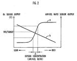
- FIG. 2 is a diagram showing output characteristics of an O 2 sensor and an air-fuel ratio sensor used in the apparatus shown in FIG. 1
- FIG. 3 is a block diagram showing a basic arrangement of an exhaust-side main processor of the apparatus shown in FIG. 1
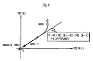
- FIG. 4 is a diagram illustrative of a sliding mode control process employed by the apparatus shown in FIG. 1
- FIG. 5 is a diagram illustrative of a process of evaluating the deteriorated state of a catalytic converter employed by the apparatus shown in FIG. 1;
- FIG. 1 is a block diagram of an overall system arrangement of an apparatus for controlling the air-fuel ratio of an internal combustion engine according to a first embodiment of the present invention
- FIG. 2 is a diagram showing output characteristics of an O 2 sensor and an air-fuel ratio sensor used in the apparatus shown in FIG. 1
- FIG. 3 is
- FIG. 6 is a diagram illustrative of the process of evaluating the deteriorated state of the catalytic converter employed by the apparatus shown in FIG. 1;
- FIG. 7 is a diagram illustrative of the process of evaluating the deteriorated state of the catalytic converter employed by the apparatus shown in FIG. 1;
- FIG. 8 is a diagram illustrative of the process of evaluating the deteriorated state of the catalytic converter employed by the apparatus shown in FIG. 1;
- FIG. 9 is a block diagram of an adaptive controller employed in the apparatus shown in FIG. 1;
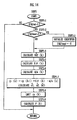
- FIG. 10 is a flowchart of a processing sequence of an engine-side control unit of the apparatus shown in FIG. 1;
- FIG. 11 is a flowchart of a subroutine of the processing sequence shown in FIG. 10;
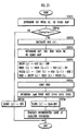
- FIG. 12 is a flowchart of a processing sequence of an exhaust-side control unit of the apparatus shown in FIG. 1;
- FIG. 13 is a flowchart of a subroutine of the processing sequence shown in FIG. 12;
- FIG. 14 is a flowchart of a subroutine of the processing sequence shown in FIG. 12;
- FIG. 15 is a flowchart of a subroutine of the processing sequence shown in FIG. 12;
- FIG. 16 is a flowchart of a subroutine of the processing sequence shown in FIG. 12;
- FIG. 17 is a flowchart of a subroutine of the processing sequence shown in FIG. 16;
- FIG. 16 is a flowchart of a subroutine of the processing sequence shown in FIG. 12;
- FIG. 17 is a flowchart of a subroutine of the processing sequence shown in FIG. 16;
- FIG. 16 is a
- FIG. 18 is a flowchart of a subroutine of the processing sequence shown in FIG. 16;
- FIG. 19 is a flowchart of a subroutine of the processing sequence shown in FIG. 16;
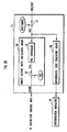
- FIG. 20 is a block diagram of an engine-side control unit of an apparatus for controlling the air-fuel ratio of an internal combustion engine according to a second embodiment of the present invention;
- FIG. 21 is a flowchart of a processing sequence of the exhaust-side control unit of the apparatus shown in FIG. 20; and
- FIG. 22 is a diagram showing a data table employed in the processing sequence shown in FIG. 21.
- FIG. 1 shows in block form the apparatus according to the embodiment.
- an internal combustion engine 1 such as a four-cylinder internal combustion engine is mounted as a propulsion source on an automobile or a hybrid vehicle, for example.
- an exhaust gas is generated and emitted from each cylinder into a common discharge pipe 2 positioned near the internal combustion engine 1, from which the exhaust gas is discharged into the atmosphere.
- Two three-way catalytic converters 3, 4 are mounted in the common exhaust pipe 2 at successively downstream locations thereon.
- the upstream catalytic converter 3 is evaluated for its deteriorated state according to the present invention.
- the downstream catalytic converter 4 may be dispensed with.
- the apparatus serves to control the air-fuel ratio of the exhaust gas entering the catalytic converter 3, or specifically the air-fuel ratio recognized from the oxygen concentration in the exhaust gas entering the catalytic converter 3 (hereinafter referred to as the "air-fuel ratio of the internal combustion engine") in order to achieve an optimum purifying capability of the catalytic converter 3. While controlling the air-fuel ratio, the apparatus also evaluates the deteriorated state of the catalytic converter 3.
- the apparatus has an air-fuel ratio sensor 5 mounted on the exhaust pipe 2 upstream of the catalytic converter 3, or more precisely at a position where exhaust gases from the cylinders of the internal combustion engine 1 are put together, an O 2 sensor (oxygen concentration sensor) 6 mounted as an exhaust gas sensor on the exhaust pipe 2 downstream of the catalytic converter 3 and upstream of the catalytic converter 4, and a control unit 7 for carrying out a control process (described later on) and evaluating the deteriorated state of the catalytic converter 3 based on detected outputs from the sensors 5, 6.
- an air-fuel ratio sensor 5 mounted on the exhaust pipe 2 upstream of the catalytic converter 3, or more precisely at a position where exhaust gases from the cylinders of the internal combustion engine 1 are put together
- an O 2 sensor (oxygen concentration sensor) 6 mounted as an exhaust gas sensor on the exhaust pipe 2 downstream of the catalytic converter 3 and upstream of the catalytic converter 4
- a control unit 7 for carrying out a control process (described later on) and evaluating the deteriorated
- the control unit 7 is supplied with detected outputs from the sensors 5, 6 and also detected outputs from various other sensors for detecting operating conditions of the internal combustion engine 1, including a engine speed sensor, an intake pressure sensor, a coolant temperature sensor, etc.
- the O 2 sensor 6 comprises an ordinary O 2 sensor for generating an output VO2/OUT having a level depending on the oxygen concentration in the exhaust gas that has passed through the catalytic converter 3, i.e., an output VO2/OUT representing a detected value of the oxygen concentration of the exhaust gas.
- the oxygen concentration in the exhaust gas is commensurate with the air-fuel ratio of an air-fuel mixture which, when combusted, produces the exhaust gas.
- the output VO2/OUT from the O 2 sensor 6 will change with high sensitivity in proportion to the oxygen concentration in the exhaust gas, with the air-fuel ratio corresponding to the oxygen concentration in the exhaust gas being in a range ⁇ close to a stoichiometric air-fuel ratio, as indicated by the solid-line curve a in FIG. 2.
- the output VO2/OUT from the O 2 sensor 6 is saturated and is of a substantially constant level.
- the air-fuel ratio sensor 5 generates an output KACT representing a detected value of the air-fuel ratio of the internal combustion engine 1 which is recognized from the concentration of oxygen in the exhaust gas that enters the catalytic converter 3.
- the air-fuel ratio sensor 5 comprises a wide-range air-fuel ration sensor disclosed in detail in Japanese laid-open patent publication No. 4-369471, which corresponds to U.S. patent No. 5,391,282. As indicated by the solid-line curve b in FIG. 2, the air-fuel ratio sensor 5 generates an output whose level is proportional to the concentration of oxygen in the exhaust gas in a wider range than the O 2 sensor 6. Stated otherwise, the air-fuel ratio sensor 5 (hereinafter referred to as "LAF sensor 5”) generates an output whose level corresponding to the concentration of oxygen in the exhaust gas in a wide range of air-fuel ratios.
- the control unit 7 comprises a control unit 7a (hereinafter referred to as an “exhaust-side control unit 7a”) for performing a process of calculating a target air-fuel ratio KCMD as a manipulated variable for determining the air-fuel ratio of the internal combustion engine 1 and carrying out a process of evaluating the deteriorated state of the catalytic converter 3, and a control unit 7b (hereinafter referred to as an “engine-side control unit 7b”) for carryout out a process of controlling the air-fuel ratio of an air-fuel ratio to be combusted in the internal combustion engine 1 based on the target air-fuel ratio KCMD by adjusting the fuel injection quantity (fuel supply quantity) of the internal combustion engine 1 depending on the target air-fuel ratio KCMD.
- a control unit 7a for performing a process of calculating a target air-fuel ratio KCMD as a manipulated variable for determining the air-fuel ratio of the internal combustion engine 1 and carrying out a process of evaluating the deteriorated state of the cat
- the control units 7a, 7b comprise a microcomputer, and perform their respective control processes in given control cycles.
- each of the control cycles in which the exhaust-side control unit 7a performs its processes of generating the target air-fuel ratio KCMD and evaluating the deteriorated state of the catalytic converter 3 has a predetermined period (e.g., ranging from 30 to 100 ms) in view of the dead time (described later on) present in the catalytic converter 3, calculating loads, etc.
- the process of adjusting the fuel injection quantity which is carried out by the engine-side control unit 7b, needs to be in synchronism with the rotational speed of the internal combustion engine 1, or more specifically combustion cycles of the internal combustion engine 1. Therefore, each of the control cycles in which the engine-side control unit 7b performs its process has a period in synchronism with the crankshaft angle period (so-called TDC) of the internal combustion engine 1.
- the constant period of the control cycles of the exhaust-side control unit 7a is longer than the crankshaft angle period (so-called TDC) of the internal combustion engine 1.
- the engine-side control unit 7b will further be described below with reference to FIG. 1.
- the engine-side control unit 7b has, as its main functions, a basic fuel injection quantity calculator 8 for determining a basic fuel injection quantity Tim to be injected into the internal combustion engine 1, a first correction coefficient calculator 9 for determining a first correction coefficient KTOTAL to correct the basic fuel injection quantity Tim, and a second correction coefficient calculator 10 for determining a second correction coefficient KCMDM to correct the basic fuel injection quantity Tim.
- the basic fuel injection quantity calculator 8 determines a reference fuel injection quantity (fuel supply quantity) from the rotational speed NE and intake pressure PB of the internal combustion engine 1 using a predetermined map, and corrects the determined reference fuel injection quantity depending on the effective opening area of a throttle valve (not shown) of the internal combustion engine 1, thereby calculating a basic fuel injection quantity Tim.
- the first correction coefficient KTOTAL determined by the first correction coefficient calculator 9 serves to correct the basic fuel injection quantity Tim in view of an exhaust gas recirculation ratio of the internal combustion engine 1, i.e., the proportion of an exhaust gas contained in an air-fuel mixture introduced into the internal combustion engine 1, an amount of purged fuel supplied to the internal combustion engine 1 when a canister (not shown) is purged, a coolant temperature, an intake temperature, etc.
- the second correction coefficient KCMDM determined by the second correction coefficient calculator 10 serves to correct the basic fuel injection quantity Tim in view of the charging efficiency of an air-fuel mixture due to the cooling effect of fuel flowing into the internal combustion engine 1 depending on a target air-fuel ratio KCMD determined by the exhaust-side control unit 7a, as described later on.
- the engine-side control unit 7b corrects the basic fuel injection quantity Tim with the first correction coefficient KTOTAL and the second correction coefficient KCMDM by multiplying the basic fuel injection quantity Tim by the first correction coefficient KTOTAL and the second correction coefficient KCMDM, thus producing a demand fuel injection quantity Tcyl for the internal combustion engine 1.
- the engine-side control unit 7b also has, in addition to the above functions, a feedback controller 14 for feedback-controlling the air-fuel ratio of the air-fuel mixture to be combusted in the internal combustion engine 1 by adjusting a fuel injection quantity of the internal combustion engine 1 so as to converge the output KACT of the LAF sensor 5 (the detected air-fuel ratio of the internal combustion engine 1) toward the target air-fuel ratio KCMD which is calculated by the exhaust-side control unit 7a.
- the feedback controller 14 comprises a general feedback controller 15 for feedback-controlling a total fuel injection quantity for all the cylinders of the internal combustion engine 1 and a local feedback controller 16 for feedback-controlling a fuel injection quantity for each of the cylinders of the internal combustion engine 1.
- the general feedback controller 15 sequentially determines a feedback correction coefficient KFB to correct the demand fuel injection quantity Tcyl (by multiplying the demand fuel injection quantity Tcyl) so as to converge the output KACT from the LAF sensor 5 toward the target air-fuel ratio KCMD.
- the general feedback controller 15 comprises a PID controller 17 for generating a feedback manipulated variable KLAF as the feedback correction coefficient KFB depending on the difference between the output KACT from the LAF sensor 5 and the target air-fuel ratio KCMD according to a known PID control process, and an adaptive controller 18 (indicated by "STR" in FIG. 1) for adaptively determining a feedback manipulated variable KSTR for determining the feedback correction coefficient KFB in view of changes in operating conditions of the internal combustion engine 1 or characteristic changes thereof from the output KACT from the LAF sensor 5 and the target air-fuel ratio KCMD.
- STR adaptive controller 18
- the feedback manipulated variable KLAF generated by the PID controller 17 is of "1" and can be used directly as the feedback correction coefficient KFB when the output KACT (the detected air-fuel ratio) from the LAF sensor 5 is equal to the target air-fuel ratio KCMD.
- the feedback manipulated variable KSTR generated by the adaptive controller 18 becomes the target air-fuel ratio KCMD when the output KACT from the LAF sensor 5 is equal to the target air-fuel ratio KCMD.
- the feedback manipulated variable KLAF generated by the PID controller 17 and the feedback manipulated variable kstr which is produced by dividing the feedback manipulated variable KSTR from the adaptive controller 18 by the target air-fuel ratio KCMD are selected one at a time by a switcher 20.
- a selected one of the feedback manipulated variable KLAF and the feedback manipulated variable KSTR is used as the feedback correction coefficient KFB.
- the demand fuel injection quantity Tcyl is corrected by being multiplied by the feedback correction coefficient KFB. Details of the general feedback controller 15 (particularly, the adaptive controller 18) will be described later on.
- the observer 21 estimates a real air-fuel ratio #nA/F of each of the cylinders as follows:
- a system from the internal combustion engine 1 to the LAF sensor 5 (where the exhaust gases from the cylinders are combined) is considered to be a system for generating an air-fuel ratio detected by the LAF sensor 5 from a real air-fuel ratio #nA/F of each of the cylinders, and is modeled in view of a detection response delay (e.g., a time lag of first order) of the LAF sensor 5 and a chronological contribution of the air-fuel ratio of each of the cylinders to the air-fuel ratio detected by the LAF sensor 5.
- a detection response delay e.g., a time lag of first order
- Each of the PID controllers 22 of the local feedback controller 16 divides the output signal KACT from the LAF sensor 5 by an average value of the feedback correction coefficients #nKLAF determined by the respective PID controllers 22 in a preceding control cycle to produce a quotient value, and uses the quotient value as a target air-fuel ratio for the corresponding cylinder.
- Each of the PID controllers 22 determines a feedback correction coefficient #nKLAF in a present control cycle so as to eliminate any difference between the target air-fuel ratio and the corresponding real air-fuel ratio #nA/F determined by the observer 21.
- the output fuel injection quantity #nTout thus determined for each of the cylinders is corrected for accumulated fuel particles on intake pipe walls of the internal combustion engine 1 by a fuel accumulation corrector 23 in the engine-side control unit 7b.
- the corrected output fuel injection quantity #nTout is applied to each of fuel injectors (not shown) of the internal combustion engine 1, which injects fuel into each of the cylinders with the corrected output fuel injection quantity #nTout.
- a sensor output selector 24 shown in FIG. 1 serves to select the output KACT from the LAF sensor 5, which is suitable for the estimation of a real air-fuel ratio #nA/F of each cylinder with the observer 21, depending on the operating conditions of the internal combustion engine 1. Details of the sensor output selector 24 are disclosed in detail in Japanese laid-open patent publication No. 7-259588 and U.S. patent No. 5,540,209, and will not be described in detail below.
- the catalytic converter 3 achieves an optimum purifying capability irrespective of its deteriorated state at the air-fuel ratio of the internal combustion engine 1 which causes the output VO2/OUT from the O 2 sensor 6 to settle on a certain constant value VO2/TARGET (see FIG. 2).
- the constant value VO2/TARGET is used as the target value VO2/TARGET for the output VO2/OUT from the O 2 sensor 6.
- the reference value FLAF/BASE with respect to the output KACT from the LAF sensor 5 is set to a "stoichiometric air-fuel ratio".
- the differences kact, VO2 determined respectively by the subtractors 11, 12 are referred to as a differential output kact of the LAF sensor 5 and a differential output VO2 of the O 2 sensor 6, respectively.
- the exhaust-side control unit 7a also has an exhaust-side main processor 13 which is supplied with the data of the differential outputs kact, VO2 as the data of the output from the LAF sensor 5 and the output of the O 2 sensor 6.
- the exhaust-side main processor 13 comprises, as its functions, a target air-fuel ratio calculating means 13a as an air-fuel ratio manipulated variable determining means for sequentially determining a target air-fuel ratio KCMD for the internal combustion engine 1 based on the data of the differential outputs kact, VO2, and a deteriorated state evaluating means 13b for evaluating the deteriorated state of the catalytic converter 3 based on the data of the differential output VO2 of the O 2 sensor 6.
- a target air-fuel ratio calculating means 13a as an air-fuel ratio manipulated variable determining means for sequentially determining a target air-fuel ratio KCMD for the internal combustion engine 1 based on the data of the differential outputs kact, VO2, and a deteriorated state evaluating means 13b for evaluating the deteriorated state of the catalytic converter 3 based on the data of the differential output VO2 of the O 2 sensor 6.
- the target air-fuel ratio calculating means 13a serves to control an object exhaust system (denoted by E in FIG. 1) including the catalytic converter 3, which ranges from the LAF sensor 5 to the O 2 , sensor 6 along the exhaust pipe 2.
- the target air-fuel ratio calculating means 13a sequentially determines the target air-fuel ratio KCMD for the internal combustion engine 1 so as to converge the output VO2/OUT of the O 2 sensor 6 to the target value VO2/TARGET therefor according to a sliding mode control process, or specifically an adaptive sliding mode control process, in view of a dead time present in the object exhaust system E to be controlled, a dead time present in the internal combustion engine 1 and the engine-side control unit 7b, and behavioral changes of the object exhaust system E.
- the deteriorated state evaluating means 13b serves to evaluate the deteriorated state of the catalytic converter 3 based on the value of a deterioration evaluating linear function, described later on, which is determined from time-series data of the differential output VO2 of the O 2 sensor 6, and control the operation of a deterioration indicator 29 connected to the air-fuel ratio control apparatus depending on the evaluation of the deteriorated state of the catalytic converter 3.
- the deterioration indicator 29 may comprise a lamp, a buzzer, or a display unit for displaying characters, a graphic image, etc. to indicate the deteriorated state of the catalytic converter 3.
- the target air-fuel ratio calculating means 13a and the deteriorated state evaluating means 13b will further be described below.
- the object exhaust system E is regarded as a system for generating the output VO2/OUT of the O 2 sensor 6 (the detected value of the oxygen concentration of the exhaust gas having passed through the catalytic converter 3) from the output KACT of the LAF sensor 5 (the detected value of the air-fuel ratio of the internal combustion engine 1) via a dead time element and a response delay element, and the behavior of the system is modeled as a discrete time system.
- the system comprising the internal combustion engine 1 and the engine-side control unit 7b is regarded as a system (hereinafter referred to as "air-fuel ratio manipulating system") for generating the output KACT of the LAF sensor 5 from the target air-fuel ratio KCMD via a dead time element, and the behavior of this system is modeled as a discrete time system.
- air-fuel ratio manipulating system for generating the output KACT of the LAF sensor 5 from the target air-fuel ratio KCMD via a dead time element, and the behavior of this system is modeled as a discrete time system.
- the object exhaust system E is regarded as a system for generating the differential output VO2 from the O 2 sensor 6 from the differential output kact from the LAF sensor 5 via a dead time element and a response delay element, and expresses the behavior of the object exhaust system E with the model of a discrete time system (more specifically, an autoregressive model having a dead time in the differential output kact as an input to the exhaust system
- "k” represents the ordinal number of a discrete-time control cycle of the exhaust-side control unit 7a
- "d1" the dead time (more specifically, the dead time required until the air-fuel ratio detected at each point of time by the LAF sensor 5 is reflected in the output VO2/OUT of the O 2 sensor 6) of the object exhaust system E as represented by the number of control cycles.
- the first and second terms of the right side of the equation (1) correspond to a response delay element of the object exhaust system E, the first term being a primary autoregressive term and the second term being a secondary autoregressive term.
- "a1", "a2" represent respective gain coefficients of the primary autoregressive term and the secondary autoregressive term. Stated otherwise, these gain coefficients a1, a2 are relative to the differential output VO2 of the O 2 sensor 6 as an output of the control system E.
- the third term of the right side of the equation (1) represents the differential output kact of the LAF sensor 5 as an input to the object exhaust system E, including the dead time d1 of the object exhaust system E.
- "b1" represents a gain coefficient relative to the input to the object exhaust system E, i.e., the differential output kact of the LAF sensor 5.
- the equation (2) expresses the air-fuel ratio manipulating system as the model of a discrete time system, regarding the air-fuel ratio manipulating system as a system for generating the differential output kact from the LAF sensor 5 from the target differential air-fuel ratio kcmd via a dead time element, i.e., a system in which the differential output kact in each control cycle is equal to the target differential air-fuel ratio kcmd prior to the dead time.
- "d2" represents the dead time of the air-fuel ratio manipulating system (more specifically, the time required until the target air-fuel ratio KCMD at each point of time is reflected in the output signal KACT of the LAF sensor 5) in terms of the number of control cycles of the exhaust-side control unit 7a.
- the dead time of the air-fuel ratio manipulating system varies with the rotational speed NE of the internal combustion engine 1, and is longer as the rotational speed NE of the internal combustion engine 1 is lower.
- the air-fuel ratio manipulating system actually includes a dead time element and a response delay element of the internal combustion engine 1. Since a response delay of the output KACT of the LAF sensor 5 with respect to the target air-fuel ratio KCMD is basically compensated for by the feedback controller 14 (particularly the adaptive controller 18) of the engine-side control unit 7b, there will arise no problem if a response delay element of the internal combustion engine 1 is not taken into account in the air-fuel ratio manipulating system as viewed from the exhaust-side control unit 7a.
- the target air-fuel ratio calculating means 13a of the exhaust-side main processor 13 carries out the process for calculating the target air-fuel ratio KCMD based on the exhaust system model and the air-fuel ratio manipulating system model expressed respectively by the equations (1), (2) in constant control cycles of the exhaust-side control unit 7a.
- the target air-fuel ratio calculating means 13a has its functions as shown in FIG. 3.
- the algorithm of a processing operation to be carried out by the identifier 25, the estimator 26, and the sliding mode controller 27 is constructed as follows:
- the identifier 25 serves to identify the gain coefficients a1, a2, b1 sequentially on a real-time basis for the purpose of minimizing a modeling error of the actual object exhaust system E of the exhaust system model expressed by the equation (1).
- the identifier 25 carries out its identifying process as follows:
- the equation (3) corresponds to the equation (1) which is shifted into the past by one control cycle with the gain coefficients a1, a2, b1 being replaced with the respective identified gain coefficients a1(k-1) hat, a2(k-1) hat, b1(k-1) hat.
- the identifier 25 further determines new identified gain coefficients a1(k) hat, a2(k) hat, b1(k) hat, stated otherwise, a new vector ⁇ (k) having these identified gain coefficients as elements (hereinafter the new vector ⁇ (k) will be referred to as "identified gain coefficient vector ⁇ "), in order to minimize the identified error id/e, according to the equation (8) given below.
- the identifier 25 varies the identified gain coefficients a1 hat (k-1), a2 hat (k-1), b1 hat (k-1) determined in the preceding control cycle by a quantity proportional to the identified error id/e(k) for thereby determining the new identified gain coefficients a1(k) hat, a2(k) hat, b1(k) hat.
- K ⁇ a cubic vector determined by the following equation (9), i.e., a gain coefficient vector for determining a change depending on the identified error id/e of the identified gain coefficients a1 hat, a2 hat, b1 hat):
- K ⁇ (k) P(k-1) ⁇ (k) 1+ ⁇ T (k) ⁇ P(k-1) ⁇ (k) where P represents a cubic square matrix determined by a recursive formula expressed by the following equation (10): where I represents a unit matrix.
- ⁇ 1 , ⁇ 2 are established to satisfy the conditions 0 ⁇ ⁇ 1 ⁇ 1 and 0 ⁇ ⁇ 2 ⁇ 2, and an initial value P(0) of P represents a diagonal matrix whose diagonal components are positive numbers.
- any one of various specific algorithms including a fixed gain method, a degressive gain method, a method of weighted least squares, a method of least squares, a fixed tracing method, etc. may be employed.
- the identifier 25 sequentially determines in each control cycle the identified gain coefficients a1 hat, a2 hat, b1 hat of the exhaust system model in order to minimize the identified error id/e according to the above algorithm (calculating operation). Through this operation, it is possible to sequentially obtain the identified gain coefficients a1 hat, a2 hat, b1 hat which match the actual object exhaust system E.
- the algorithm described above is the basic algorithm that is carried cut by the identifier 25.
- the algorithm for the estimator 26 to determine the estimated differential output VO2 bar is constructed as follows:
- the equation (11) expresses the behavior of a system which is a combination of the object exhaust system E and the air-fuel manipulating system as the model of a discrete time system, regarding such a system as a system for generating the differential output VO2 from the O 2 sensor 6 from the target differential air-fuel ratio kcmd via dead time elements of the object exhaust system E and the air-fuel manipulating system and a response delay element of the object exhaust system E.
- the time-series data kcmd(k-d2), kcmd(k-d2-1), ⁇ , kcmd(k-d) from the present prior to the dead time d2 of the air-fuel manipulating system can be replaced respectively with data kact(k), kact(k-1), ⁇ , kact(k-d+d2) obtained prior to the present time of the differential output kact of the LAF sensor 5.
- equation (13) is obtained:
- the values of the dead times d1, d2 required in the equation (13) comprise the preset values as described above.
- the estimated differential output VO2(k+d) bar may be determined according to the equation (12) without using the data of the differential output kact of the LAF sensor 5.
- the dead time d2 of the air-fuel ratio manipulating system can be set to "1"
- the estimated differential output VO2(k+d) bar can be determined according to the following equation (14) which does not include the data of the target differential air-fuel ratio kcmd:
- the sliding mode controller 27 will be described in detail below.
- the sliding mode controller 27 determines an input quantity to be given to the object exhaust system E (which is specifically a target value for the difference between the output KACT of the LAF sensor 5 (the detected value of the air-fuel ratio) and the reference value FLAF/BASE, which target value is equal to the target differential air-fuel ratio kcmd) (the input quantity will be referred to as "SLD manipulating input Usl") in order to cause the output VO2/OUT of the O 2 sensor 6 to settle on the target value VO2/TARGET, i.e., to converge the differential output VO2 of the O 2 sensor 6 to "0" according to an adaptive sliding mode control process which incorporates an adaptive control law for minimizing the effect of a disturbance, in a normal sliding mode control process, and determines the target air-fuel ratio KCMD from the determined SLD manipulating input Usl.
- An algorithm for carrying out the adaptive sliding mode control process is constructed as follows:
- a switching function required for the algorithm of the adaptive sliding mode control process carried out by the sliding mode controller 27 and a hyperplane defined by the switching function (also referred to as a slip plane) will first be described below.
- a vector X defined above with respect to the equation (15) as a vector whose elements are represented by the differential outputs VO2(k), VO2(k-1) will hereinafter be referred to as a state quantity X.
- the time-series data of the estimated differential output VO2 bar determined by the estimator 26 is used as the variable components of the switching function for the sliding mode control process, as described later on.
- Usl Ueq + Urch + Uadp
- the equivalent control input Ueq, the reaching control law input Urch, and the adaptive control law input Uadp are determined on the basis of the model of the discrete time system expressed by the equation (11), i.e., the model in which the differential output kact(k-d1) of the LAF sensor 5 in the equation (11) is replaced with the target differential air-fuel ratio kcmd(k-d) using the total dead time 3, as follows:
- the equation (18) is a basic formula for determining the equivalent control law input Ueq(k) in each control cycle.
- the reaching control law input Urch is determined in proportion to the value ⁇ (k+d) of the switching function ⁇ after the total dead time d, in view of the effect of the total dead time d.
- chattering an oscillating fashion
- the coefficient F relative to the reaching control law input Urch be established to further satisfy the condition of the following equation (21): 0 ⁇ F ⁇ 1
- the adaptive control law input Uadp is basically determined according to the following equation (22) ( ⁇ T in the equation (22) represents the period of the control cycles of the exhaust-side control unit 7a):
- the adaptive control law input Uadp is determined in proportion to an integrated value (which corresponds to an integral of the values of the switching function ⁇ ) over control cycles of the product of values of the switching function ⁇ and the period ⁇ T of the exhaust-side control unit 7a until after the total dead time d, in view of the effect of the total dead time d.
- the sliding mode controller 27 determines the sum (Ueq + Urch + Uadp) of the equivalent control input Ueq, the reaching control law input Urch, and the adaptive control law Uadp determined according to the respective equations (18), (19), (22) as the SLD manipulating input Usl to be applied to the object exhaust system E.
- the differential outputs VO2(K+d), VO2(k+d-1) of the O 2 sensor 6 and the value ⁇ (k+d) of the switching function ⁇ , etc. used in the equations (18), (19), (22) cannot directly be obtained as they are values in the future.
- the sliding mode controller 27 actually uses the estimated differential outputs VO2(k+d) bar, VO2(k+d-1) bar determined by the estimator 26, instead of the differential outputs VO2(k+d), VO2(k+d-1) from the O 2 sensor 6 for determining the equivalent control input Ueq according to the equation (18), and calculates the equivalent control input Ueq in each control cycle according to the following equation (24):
- Ueq(k) -1 s1b1 ⁇ [s1 ⁇ (a1-1)+s2] ⁇ VO2 (k+d) + (s1 ⁇ a2-s2) ⁇ VO2 (k+d-1) ⁇
- the sliding mode controller 27 calculates the reaching control law input Urch in each control cycle according to the following equation (26), using the switching function ⁇ bar represented by the equation (25), rather than the value of the switching function ⁇ for determining the reaching control law input Urch according to the equation (19):
- Urch(k) -1 s1 ⁇ b1 ⁇ F ⁇ ⁇ (k+d)
- the sliding mode controller 27 calculates the adaptive control law input Uadp in each control cycle according to the following equation (27), using the value of the switching function ⁇ bar represented by the equation (25), rather than the value of the switching function ⁇ for determining the adaptive control law input Uadp according to the equation (22):
- the latest identified gain coefficients a1(k) hat, a2(k) hat, b1(k) hat which have been determined by the identifier 25 are basically used as the gain coefficients a1 a2, b1 that are required to calculate the equivalent control input Ueq, the reaching control law input Urch, and the adaptive control law input Uadp according to the equations (24), (26), (27).
- the sliding mode controller 27 determines the sum of the equivalent control input Ueq, the reaching control law input Urch, and the adaptive control law input Uadp determined according to the equations (24), (26), (27), as the SLD manipulating input Usl to be applied to the object exhaust system E (see the equation (17)).
- the conditions for establishing the coefficients s1, s2, F, G used in the equations (24), (26), (27) are as described above.
- the SLD manipulating input Usl is determined to converge the estimated differential output VO2 bar from the O 2 sensor 6 toward "0", and as a result, to convert the output VO2/OUT from the O 2 sensor 6 toward the target value VO2/TARGET.
- the sliding mode controller 27 eventually sequentially determines the target air-fuel ratio KCMD in each control cycle.
- the SLD manipulating input Usl determined as described above signifies a target value for the difference between the air-fuel ratio of the exhaust gas detected by the LAF sensor 5 and the reference value FLAF/BASE, i.e., the target differential air-fuel ratio kcmd. Consequently, the sliding mode controller 27 eventually determines the target air-fuel ratio KCMD by adding the reference value FLAF/BASE to the determined SLD manipulating input Usl in each control cycle according to the following equation (28):
- the above process is a basic algorithm for determining the target air-fuel ratio KCMD with the sliding mode controller 27 according to the present embodiment.
- the stability of the adaptive sliding mode control process carried out by the sliding mode controller 27 is checked for limiting the value of the SLD manipulating input Usl. Details of such a checking process will be described later on.
- FIGS. 5 through 7 show sampled data, represented by stippled dots, of the set of the time-series data VO2(k), VO2(k-1) of the differential output VO2 of the O 2 sensor 6, i.e., the state quantity X, which are obtained in respective control cycles of the exhaust-side control unit 7a when the fuel injection quantity of the internal combustion engine 1 is adjusted depending on the target air-fuel ratio KCMD, with respect to a brand-new catalytic converter 3, a catalytic converter 3 that has been deteriorated to a relatively small degree, and a catalytic converter 3 that has been deteriorated to a relatively large degree.
- the state quantities X tend to be distributed more widely as the catalytic converter 3 is deteriorated to a larger degree, i.e., as the deterioration of the catalytic converter 3 progresses more greatly.
- the switching function ⁇ bar determined by the equation (25) where the estimated differential output VO2 bar determined by the estimator 26 is used as a variable component, i.e., the switching function used actually as the switching function for the sliding mode control process.
- the switching function ⁇ bar employs the estimated value of the differential output VO2 of the O 2 sensor 6
- the switching function according to the equation (15) employs the actual differential output VO2 of the O 2 sensor 6. Therefore, the latter appears to better reflect the actual deteriorated state of the catalytic converter 3.
- the deteriorated state of the catalytic converter 3 is evaluated based on the value of the switching function ⁇ according to the equation (15).
- the actual switching function for the sliding mode control process is the switching function ⁇ bar defined according to the equation (25) where the estimated differential output VO2 bar determined by the estimator 26 is used as a variable component.
- the switching function ⁇ according to the equation (15) is not the switching function for the sliding mode control process according to the present embodiment.
- the switching function ⁇ according to the equation (15) will hereinafter be referred to as "deterioration evaluating linear function ⁇ ".
- An algorithm for evaluating the deteriorated state of the catalytic converter 3 based on the deterioration evaluating linear function ⁇ with the deteriorated state evaluating means 13b is constructed as follows:
- the deteriorated state evaluating means 13b sequentially determines the square ⁇ 2 of the value of the deterioration evaluating linear function ⁇ in each control cycle.
- the deteriorated state evaluating means 13b effects a low-pass filtering process on the square ⁇ 2 to determine a central value of the square ⁇ 2 (hereinafter represented by LS ⁇ 2 ) as a deterioration evaluating parameter.
- LS ⁇ 2 (k) LS ⁇ 2 (k-1) + BP(k-1) 1+ BP(k - 1) ⁇ ( ⁇ 2 (k)-LS ⁇ 2 (k-1))
- the deterioration evaluating parameter LS ⁇ 2 is determined while being sequentially updated, in each control cycle of the exhaust-side control unit 7a, from a previous value LS ⁇ 2 (k-1) of the deterioration evaluating parameter LS ⁇ 2 , a present value ⁇ 2 (k) of the square ⁇ 2 , and a gain parameter BP updated in each control cycle by a recursive formula expressed by the following equation (30):
- ⁇ 1, ⁇ 2 are set to values that satisfy the conditions: 0 ⁇ ⁇ 1 ⁇ 1 and 0 ⁇ ⁇ 2 ⁇ 2.
- various specific algorithms including a fixed gain method, a degression method, a method of weighted least squares, a method of least squares, a fixed tracing method, etc. are constructed.
- FIG. 8 shows the relationship between the deterioration evaluating parameter LS ⁇ 2 determined as described above and the rate of flow of the exhaust gas through the catalytic converter 3 (hereinafter referred to as "exhaust gas volume") at the respective deteriorated states of the catalytic converters 3 shown in FIGS. 5 through 7.
- the deterioration evaluating parameter LS ⁇ 2 remains substantially constant irrespective of the exhaust gas volume at each of the deteriorated states of the catalytic converters 3, and increases its value as the deterioration of the catalytic converters 3 progresses. Therefore, the deterioration evaluating parameter LS ⁇ 2 represents the degree to which the catalytic converter 3 is deteriorated.
- the deteriorated state of the catalytic converter 3 is evaluated to judge whether the catalytic converter 3 is in a state where it has been deteriorated to the extent that it needs to be replaced immediately or soon (such a deteriorated state will hereinafter be referred to as "deterioration-in-progress state", or not (a state of the catalytic converter 3 which is not in the deterioration-in-progress state will hereinafter be referred to as "non-deteriorated state").
- the deterioration-in-progress state is indicated by the deterioration indicator 29.
- a threshold CATAGELMT is preset with respect to the deterioration evaluating parameter LS ⁇ 2 . If the deterioration evaluating parameter LS ⁇ 2 is equal to or greater than the threshold CATAGELMT, then the catalytic converter 3 is judged as being in the deterioration-in-progress state. If the deterioration evaluating parameter LS ⁇ 2 is smaller than the threshold CATAGELMT, then the catalytic converter 3 is judged as being in the non-deteriorated state.
- the algorithm described above is a basic algorithm for evaluating the deteriorated state of the catalytic converter 3 with the deteriorated state evaluating means 13b.
- the deteriorated state evaluating means 13b also performs an additional process of recognizing how the exhaust gas volume changes upon evaluating the deteriorated state of the catalytic converter 3. Such an additional process of recognizing how the exhaust gas volume changes will be described later on.
- the general feedback controller 15 of the engine-side control unit 7b particularly, the adaptive controller 18, will further be described below.
- the general feedback controller 15 effects a feedback control process to converge the output KACT (the detected value of the air-fuel ratio) from the LAF sensor 5 toward the target air-fuel ratio KCMD as described above. If such a feedback control process were carried out under the known PID control only, it would be difficult keep stable controllability against dynamic behavioral changes including changes in the operating conditions of the internal combustion engine 1, characteristic changes due to aging of the internal combustion engine 1, etc.
- the adaptive controller 18 is a recursive-type controller which makes it possible to carry out a feedback control process while compensating for dynamic behavioral changes of the internal combustion engine 1.
- the adaptive controller 18 comprises a parameter adjuster 30 for establishing a plurality of adaptive parameters using the parameter adjusting law proposed by I. D. Landau, et al., and a manipulated variable calculator 31 for calculating the feedback manipulated variable KSTR using the established adaptive parameters.
- the parameter adjuster 30 will be described below. According to the parameter adjusting law proposed by I. D. Landau, et al., when polynomials of the denominator and the numerator of a transfer function B(Z -1 )/A(Z -1 ) of a discrete-system object to be controlled are generally expressed respectively by equations (31), (32), given below, an adaptive parameter ⁇ hat (j) (j indicates the ordinal number of a control cycle) established by the parameter adjuster 30 is represented by a vector (transposed vector) according to the equation (33) given below. An input ⁇ (j) to the parameter adjuster 30 is expressed by the equation (34) given below.
- ys generally represent an input (manipulated variable) to the object to be controlled and an output (controlled variable) from the object to be controlled.
- the input is the feedback manipulated variable KSTR and the output from the object (the internal combustion engine 1) is the output KACT (detected air-fuel ratio) from the LAF sensor 5, and the input ⁇ (j) to the parameter adjuster 30 is expressed by the lower expression of the equation (34) (see FIG. 9).
- A(Z -1 ) 1 + a1Z -1 + ⁇ + anZ -n
- B(Z -1 ) b0 + b1Z -1 + ⁇ + bmZ -m
- the parameter adjuster 30 establishes coefficients of the scalar quantity element and the control elements, described above, and supplies them as the adaptive parameter ⁇ hat expressed by the equation (33) to the manipulated variable calculator 31.
- the parameter adjuster 30 calculates the adaptive parameter ⁇ hat so that the output KACT from the LAF sensor 5 will agree with the target air-fuel ratio KCMD, using time-series data of the feedback manipulated variable KSTR from the present to the past and the output KACT from the LAF sensor 5.
- D(Z -1 ) D(Z -1 ) ⁇ KACT(j)- ⁇ T (j-1) ⁇ (j-dp) 1+ ⁇ T (j-dp) ⁇ (j-1) ⁇ (j-dp)
- D(Z -1 ) represents an asymptotically stable polynomial for adjusting the convergence.
- D(Z -1 ) 1.
- the manipulated variable calculator 31 shown in FIG. 9 represents a block diagram of the calculations according to the equation (41).
- the feedback manipulated variable KSTR determined according to the equation (41) becomes the target air-fuel ratio KCMD insofar as the output KACT of the LAF sensor 5 agrees with the target air-fuel ratio KCMD. Therefore, the feedback manipulated variable KSTR is divided by the target air-fuel ratio KCMD by the divider 19 for thereby determining the feedback manipulated variable kstr that can be used as the feedback correction coefficient KFB.
- the adaptive controller 18 thus constructed is a recursive-type controller taking into account dynamic behavioral changes of the engine 1 which is an object to be controlled. Stated otherwise, the adaptive controller 18 is a controller described in a recursive form to compensate for dynamic behavioral changes of the engine 1, and more particularly a controller having a recursive-type adaptive parameter adjusting mechanism.
- a recursive-type controller of this type may be constructed using an optimum regulator. In such a case, however, it generally has no parameter adjusting mechanism.
- the adaptive controller 18 constructed as described above is suitable for compensating for dynamic behavioral changes of the internal combustion engine 1.
- the PID controller 17, which is provided together with the adaptive controller 18 in the general feedback controller 15, calculates a proportional term (P term), an integral term (I term), and a derivative term (D term) from the difference between the output KACT of the LAF sensor 5 and the target air-fuel ratio KCMD, and calculates the total of those terms as the feedback manipulated variable KLAF, as is the case with the general PID control process.
- the feedback manipulated variable KLAF is set to "1" when the output KACT of the LAF sensor 5 agrees with the target air-fuel ratio KCMD by setting an initial value of the integral term (I term) to "1", so that the feedback manipulated variable KLAF can be used as the feedback correction coefficient KFB for directly correcting the fuel injection quantity.
- the gains of the proportional term, the integral term, and the derivative term are determined from the rotational speed and intake pressure of the internal combustion engine 1 using a predetermined map.
- the switcher 20 of the general feedback controller 15 outputs the feedback manipulated variable KLAF determined by the PID controller 17 as the feedback correction coefficient KFB for correcting the fuel injection quantity if the combustion in the internal combustion engine 1 tends to be unstable as when the temperature of the coolant of the internal combustion engine 1 is low, the internal combustion engine 1 rotates at high speeds, or the intake pressure is low, or if the output KACT of the LAF sensor 5 is not reliable due to a response delay of the LAF sensor 5 as when the target air-fuel ratio KCMD changes largely or immediately after the air-fuel ratio feedback control process has started, or if the internal combustion engine 1 operates highly stably as when it is idling and hence no high-gain control process by the adaptive controller 18 is required.
- the switcher 20 outputs the feedback manipulated variable kstr which is produced by dividing the feedback manipulated variable KSTR determined by the adaptive controller 18 by the target air-fuel ration KCMD, as the feedback correction coefficient KFB for correcting the fuel injection quantity.
- the adaptive controller 18 effects a high-gain control process and functions to converge the output KACT of the LAF sensor 5 quickly toward the target air-fuel ratio KCMD, and if the feedback manipulated variable KSTR determined by the adaptive controller 18 is used when the combustion in the internal combustion engine 1 is unstable or the output KACT of the LAF sensor 5 is not reliable, then the air-fuel ratio control process tends to be unstable.
- the engine-side control unit 7b reads outputs from various sensors including the LAF sensor 5 and the O 2 sensor 6 in STEPa. At this time, the output KACT of the LAF sensor 5 and the output VO2/OUT of the O 2 sensor 6, including data obtained in the past, are stored in a time-series fashion in a memory (not shown).
- the basic fuel injection quantity calculator 8 corrects a fuel injection quantity corresponding to the rotational speed NE and intake pressure PB of the internal combustion engine 1 depending on the effective opening area of the throttle valve, thereby calculating a basic fuel injection quantity Tim in STEPb.
- the first correction coefficient calculator 9 calculates a first correction coefficient KTOTAL depending on the coolant temperature and the amount by which the canister is purged in STEPc.
- the engine-side control unit 7b decides whether the operation mode of the internal combustion engine 1 is an operation mode (hereinafter referred to as "normal operation mode") in which the fuel injection quantity is adjusted using the target air-fuel ratio KCMD generated by the target air-fuel ratio calculating means 13a, and sets a value of a flag f/prism/on in STEPd.
- normal operation mode an operation mode
- the value of the flag f/prism/on is "1" it means that the operation mode of the internal combustion engine 1 is the normal operation mode
- the value of the flag f/prism/on is "0"
- the deciding subroutine of STEPd is shown in detail in FIG. 11.
- the engine-side control unit 7b decides whether the O 2 sensor 6 and the LAF sensor 5 are activated or not respectively in STEPd-1, STEPd-2. If neither one of the O 2 sensor 6 and the LAF sensor 5 is activated, since detected data from the O 2 sensor 6 and the LAF sensor 5 for use by the exhaust-side main processor 13 are not accurate enough, the operation mode of the internal combustion engine 1 is not the normal operation mode, and the value of the flag f/prism/on is set to "0" in STEPd-10.
- the engine-side control unit 7b decides whether the internal combustion engine 1 is operating with a lean air-fuel mixture or not in STEPd-3.
- the engine-side control unit 7b decides whether the ignition timing of the internal combustion engine 1 is retarded for early activation of the catalytic converter 3 immediately after the start of the internal combustion engine 1 or not in STEPd-4.
- the engine-side control unit 7b decides whether the throttle valve of the internal combustion engine 1 is substantially fully open or not in STEPd-5.
- the engine-side control unit 7b decides whether the supply of fuel to the internal combustion engine 1 is being stopped or not in STEPd-6.
- the operation mode of the internal combustion engine 1 is not the normal operation mode, and the value of the flag f/prism/on is set to "0" in STEPd-10.
- the engine-side control unit 7b decides whether the rotational speed NE and the intake pressure PB of the internal combustion engine 1 fall within respective given ranges or not respectively in STEPd-7, STEPd-8. If either one of the rotational speed NE and the intake pressure PB does not fall within its given range, then since it is not preferable to control the supply of fuel to the internal combustion engine 1 using the target air-fuel ratio KCMD generated by the exhaust-side main processor 13, the operation mode of the internal combustion engine 1 is not the normal operation mode, and the value of the flag f/prism/on is set to "0" in STEPd-10.
- the predetermined value to be established as the target air-fuel ratio KCMD is determined from the rotational speed NE and intake pressure PB of the internal combustion engine 1 using a predetermined map, for example.
- the switcher 20 selects either the feedback manipulated variable KLAF determined by the PID controller 17 or the feedback manipulated variable kstr which has been produced by dividing the feedback manipulated variable KSTR determined by the adaptive controller 18 by the target air-fuel ratio KCMD (normally, the switcher 20 selects the feedback manipulated variable kstr). The switcher 20 then outputs the selected feedback manipulated variable KLAF or kstr as a feedback correction coefficient KFB.
- the second correction coefficient calculator 10 calculates in STEPj a second correction coefficient KCMDM depending on the target air-fuel ratio KCMD determined in STEPf or STEPg.
- the engine-side control unit 7b multiplies the basic fuel injection quantity Tim determined as described above, by the first correction coefficient KTOTAL, the second correction coefficient KCMDM, the feedback correction coefficient KFB, and the feedback correction coefficients #nKLAF of the respective cylinders, determining output fuel injection quantities #nTout of the respective cylinders in STEPk.
- the output fuel injection quantities #nTout are then corrected for accumulated fuel particles on intake pipe walls of the internal combustion engine 1 by the fuel accumulation corrector 23 in STEPm.
- the corrected output fuel injection quantities #nTout are applied to the non-illustrated fuel injectors of the internal combustion engine 1 in STEPn.
- the fuel injectors inject fuel into the respective cylinders according to the respective output fuel injection quantities #nTout.
- the above calculation of the output fuel injection quantities #nTout and the fuel injection of the internal combustion engine 1 are carried out in successive cycle times synchronous with the crankshaft angle period of the internal combustion engine 1 for controlling the air-fuel ratio of the internal combustion engine 1 in order to converge the output KACT of the LAF sensor 5 (the detected air-fuel ratio) toward the target air-fuel ratio KCMD.
- the feedback manipulated variable kstr from the adaptive controller 18 is being used as the feedback correction coefficient KFB
- the output KACT of the LAF sensor 5 is quickly converged toward the target air-fuel ratio KCMD with high stability against behavioral changes such as changes in the operating conditions of the internal combustion engine 1 or characteristic changes thereof.
- a response delay of the internal combustion engine 1 is also appropriately compensated for.
- the exhaust-side control unit 7a executes a main routine shown in FIG. 12 in control cycles of a constant period.
- the exhaust-side control unit 7a decides whether the processing of the exhaust-side main processor 13 is to be executed or not, and sets a value of a flag f/prism/cal indicative of whether the processing is to be executed or not in STEP1.
- the value of the flag f/prism/cal is "0" it means that the processing of the exhaust-side main processor 13 is not to be executed, and when the value of the flag f/prism/cal is "1", it means that the processing of the exhaust-side main processor 13 is to be executed.
- the deciding subroutine in STEP1 is shown in detail in FIG. 13.
- the exhaust-side control unit 7a decides whether the O 2 sensor 6 and the LAF sensor 5 are activated or not respectively in STEP1-1, STEP1-2. If neither one of the O 2 sensor 6 and the LAF sensor 5 is activated, since detected data from the O 2 sensor 6 and the LAF sensor 5 for use by the exhaust-side main processor 13 are not accurate enough, the value of the flag f/prism/cal is set to "0" in STEP1-6.
- the value of a flag f/id/reset indicative of whether the identifier 25 is to be initialized or not is set to "1" in STEP1-7.
- the value of the flag f/id/reset is "1" it means that the identifier 25 is to be initialized, and when the value of the flag f/id/reset is "0", it means that the identifier 25 is not to be initialized.
- the exhaust-side control unit 7a decides whether the internal combustion engine 1 is operating with a lean air-fuel mixture or not in STEP1-3.
- the exhaust-side control unit 7a decides whether the ignition timing of the internal combustion engine 1 is retarded for early activation of the catalytic converter 3 immediately after the start of the internal combustion engine 1 or not in STEP1-4.
- the value of the flag f/prism/cal is set to "0" in STEP1-6, and the value of the flag f/id/reset is set to "1" in order to initialize the identifier 25 in STEP1-7.
- the exhaust-side control unit 7a decides whether a process of identifying (updating) the gain coefficients a1, a2, b1 with the identifier 25 is to be executed or not, and sets a value of a flag f/id/cal indicative of whether the process of identifying (updating) the gain coefficients a1, a2, b1 is to be executed or not in STEP2.
- the exhaust-side control unit 7a decides whether the throttle valve of the internal combustion engine 1 is substantially fully open or not, and also decides whether the supply of fuel to the internal combustion engine 1 is being stopped or not. If either one of these conditions is satisfied, then since it is difficult to adjust the gain coefficients a1, a2, b1 appropriately, the value of the flag f/id/cal is set to "0". If neither one of these conditions is satisfied, then the value of the flag f/id/cal is set to "1" to identify (update) the gain coefficients a1, a2, b1 with the identifier 25.
- the exhaust-side control unit 7a determines the value of the flag f/prism/cal set in STEP1. If the value of the flag f/prism/cal is "0", i.e., if the processing of the exhaust-side main processor 13 is not to be executed, then the exhaust-side control unit 7a forcibly sets the SLD manipulating input Usl (the target differential air-fuel ratio kcmd) to be determined by the sliding mode controller 27, to a predetermined value in STEP13.
- the predetermined value may be a fixed value (e.g., "0") or the value of the SLD manipulating input Usl determined in a preceding control cycle.
- the exhaust-side control unit 7a adds the reference value FLAF/BASE to the SLD manipulating input Usl for thereby determining a target air-fuel ratio KCMD in the present control cycle in STEP 14. Then, the processing in the present control cycle is finished.
- the exhaust-side control unit 7a effects the processing of the identifier 25 in STEP5.
- the processing subroutine of STEP5 is shown in detail in FIG. 14.
- the identifier 25 determines the value of the flag f/id/cal set in STEP2 in STEP5-1. If the value of the flag f/id/cal is "0", then since the process of identifying the gain coefficients a1, a2, b1 with the identifier 25 is not carried out, control immediately goes back to the main routine shown in FIG. 12.
- the identifier 25 determines the value of the flag f/id/reset set in STEP1 with respect to the initialization of the identifier 25 in STEP5-2. If the value of the flag f/id/reset is "1", the identifier 25 is initialized in STEP5-3.
- the identified gain coefficients a1 hat, a2 hat, b1 hat are set to predetermined initial values (the identified gain coefficient vector ⁇ according to the equation (4) is initialized), and the elements of the matrix P (diagonal matrix) according to the equation (9) are set to predetermined initial values.
- the value of the flag f/id/reset is reset to "0".
- the identifier 25 calculates the identified differential output VO2(k) hat using the present identified gain coefficients a1(k-1) hat, a2(k-1) hat, b1(k-1) hat and the past data VO2(k-1), VO2(k-2), kact(k-d-1) of the differential outputs VO2, kact calculated in each control cycle in STEP3, according to the equation (3) in STEP5-4.
- the identifier 25 then calculates the vector K ⁇ (k) to be used in determining the new identified gain coefficients a1 hat, a2 hat, b1 hat according to the equation (9) in STEP5-5. Thereafter, the identifier 25 calculates the identified error id/e(k), i.e., the difference between the identified differential output VO2 hat and the actual differential output VO2 (see the equation (7)), in STEP5-6.
- the object exhaust system E including the catalytic converter 3 generally has low-pass characteristics, it is preferable to attach importance to the low-frequency behavior of the object exhaust system E in appropriately identifying the qain coefficients a1, a2, b1 of the exhaust system model.
- Both the differential output VO2 and the identified differential output VO2 hat may be filtered with the same low-pass characteristics. For example, after the differential output VO2 and the identified differential output VO2 hat have separately been filtered, the equation (7) may be calculated to determine the identified error id/e(k).
- the above filtering is carried out by a moving average process which is a digital filtering process.
- the identifier 25 calculates a new identified gain coefficient vector ⁇ (k), i.e., new identified gain coefficients a1(k) hat, a2(k) hat, b1(k) hat, according to the equation (8) using the identified error id/e(k) determined in STEPS-6 and K ⁇ (k) calculated in SETP5-5 in STEPS-7.
- the identifier 25 After having calculated the new identified gain coefficients a1(k) hat, a2(k) hat, b1(k) hat, the identifier 25 further limits the values of the gain coefficients a1 hat, a2 hat, b1 hat (elements of the identified gain coefficient vector ⁇ ) to meet predetermined conditions in STEP5-8. Then, the identifier 25 updates the matrix P(k) according to the equation (10) for the processing of a next control cycle in STEP5-9, after which control returns to the main routine shown in FIG. 12.
- the process of limiting the identified gain coefficients a1 hat, a2 hat, b1 hat in STEP5-8 comprises a process of limiting the values of the identified gain coefficients a1 hat, a2 hat, b1 hat to a certain combination, i.e., a process of limiting a point (a1 hat, a2 hat) to a given region on a coordinate plane which has the identified gain coefficients a1 hat, a2 hat as its component, and a process of limiting the value of the identified gain coefficient b1 hat within a given range.
- the values of the identified gain coefficients a1(k) hat, a2(k) hat are forcibly limited to the values of the point in the given region.
- the value of the identified gain coefficient b1(k) hat calculated in STEP5-7 exceeds the upper or lower limit of the given range, then the value of the identified gain coefficient b1(k) hat is forcibly limited to the upper or lower limit of the given range.
- the above process of limiting the identified gain coefficients a1 hat, a2 hat, b1 hat serves to maintain stability of the SLD manipulating input Usl (the target differential air-fuel ratio kcmd) calculated by the sliding mode controller 27, and hence the target air-fuel ratio KCMD.
- the preceding values a1(k-1) hat, a2(k-1) hat, b1(k-1) hat of the identified gain coefficients used to determine the new identified gain coefficients a1(k) hat, a2(k) hat, b1(k) hat in STEP5-7 are the values of the identified gain coefficients after which have been limited in STEP5-8 in the preceding control cycle.
- the exhaust-side control unit 7a determines the values of the gain coefficients a1, a2, b1 in STEP6. Specifically, if the value of the flag f/id/cal set in STEP2 is "1", i.e., if the gain coefficients a1, a2, b1 have been identified by the identifier 25, then the gain coefficients a1, a2, b1 are set to the latest identified gain coefficients a1(k) hat, a2(k) hat, b1(k) hat determined by the identifier 25 in STEP5 (limited in STEP5-8).
- the gain coefficients a1, a2, b1 are set to predetermined values, respectively.
- the exhaust-side control unit 7a effects a processing operation of the estimator 26, i.e., calculates the estimated differential output VO2 bar, in STEP7.
- the sliding mode controller 27 calculates a value ⁇ (k+d) bar (corresponding to an estimated value, after the total dead time d, of the linear function a defined according to the equation (15)), after the total dead time d from the present control cycle, of the switching function ⁇ bar defined according to the equation (25), using the time-series data VO2(k+d) bar, VO2(k+d-1) bar of the estimated differential output VO2 bar determined by the estimator 26 in STEP7.
- the sliding mode controller 27 keeps the value of the switching function ⁇ bar within a predetermined allowable range. If the value ⁇ (k+d) bar determined as described above exceeds the upper or lower limit of the allowable range, then the sliding mode controller 27 forcibly limits the value ⁇ (k+d) bar to the upper or lower limit of the allowable range. This is because if the value of the switching function ⁇ bar were excessive, the reaching control law input Urch would be excessive, and the adaptive control law Uadp would change abruptly, tending to impair the stability of the process of converging the output VO2/OUT of the O 2 sensor 6 to the target value VO2/TARGET.
- the sliding mode controller 27 accumulatively adds values ⁇ (k+d) bar ⁇ T, produced by multiplying the value ⁇ (k+d) bar of the switching function ⁇ bar by the period ⁇ T (constant period) of the control cycles of the exhaust-side control unit 7a. That is, the sliding mode controller 27 adds the product ⁇ (k+d) bar ⁇ T of the value ⁇ (k+d) bar and the period ⁇ T calculated in the present control cycle to the sum determined in the preceding control cycle, thus calculating an integrated value ⁇ bar (hereinafter represented by " ⁇ bar") which is the calculated result of the term ⁇ ( ⁇ bar ⁇ T) of the equation (27).
- the sliding mode controller 27 keeps the integrated value ⁇ bar in a predetermined allowable range. If the integrated value ⁇ bar exceeds the upper or lower limit of the allowable range, then the sliding mode controller 27 forcibly limits the integrated value ⁇ bar to the upper or lower limit of the allowable range. This is because if the integrated value ⁇ bar were excessive, the adaptive control law Uadp determined according to the equation (27) would be excessive, tending to impair the stability of the process of converging the output VO2/OUT of the O 2 sensor 6 to the target value VO2/TARGET.
- the sliding mode controller 27 calculates the equivalent control input Ueq, the reaching control law input Urch, and the adaptive control law Uadp according to the respective equations (24), (26), (27), using the time-series data VO2(k+d)bar, VO2(k+d-1) bar of the present and past values of the estimated differential output VO2 bar determined by the estimator 26 in STEP7, the value ⁇ (k+d) bar of the switching function a bar and its integrated value ⁇ bar which are determined as described above, and the gain coefficients a1, a2, b1 determined in STEP 6 (which are basically the gain coefficients a1(k) hat, a2(k) hat, b1(k) hat).
- the exhaust-side control unit 7a determines the stability of the adaptive sliding mode control process carried out by the sliding mode controller 27, or more specifically, the ability of the controlled state of the output VO2/OUT of the O 2 sensor 6 based on the adaptive sliding mode control process (hereinafter referred to as "SLD controlled state"), and sets a value of a flag f/sld/stb indicative of whether the SLD controlled state is stable or not in STEP9.
- the determining subroutine of STEP9 is shown in detail in FIG. 15.
- the exhaust-side control unit 7a calculates a difference ⁇ bar (corresponding to a rate of change of the switching function ⁇ bar) between the present value ⁇ (k+d) bar of the switching function ⁇ bar calculated in STEP8 and a preceding value ⁇ (k+d-1) bar thereof in STEP9-1.
- the exhaust-side control unit 7a decides whether or not a product ⁇ bar ⁇ (k+d) bar (corresponding to the time-differentiated function of a Lyapunov function ⁇ bar 2 /2 relative to the ⁇ bar) of the difference ⁇ bar and the present value ⁇ (k+d) bar is equal to or smaller than a predetermined value ⁇ ( ⁇ 0) in STEP9-2.
- the difference ⁇ bar ⁇ (k+d) bar (hereinafter referred to as "stability determining parameter Pstb") will be described below. If the stability determining parameter Pstb is greater than 0 (Pstb > 0), then the value of the switching function ⁇ bar is basically changing away from "0". If the stability determining parameter Pstb is equal to or smaller than 0 (Pstb ⁇ 0), then the value of the switching function ⁇ bar is basically converged or converging to "0". Generally, in order to converge a controlled variable to its target value according to the sliding mode control process, it is necessary that the value of the switching function be stably converged to "0". Basically, therefore, it is possible to determine whether the SLD controlled state is stable or unstable depending on whether or not the value of the stability determining parameter Pstb is equal to or smaller than 0.
- the predetermined value ⁇ with which the stability determining parameter Pstb is to be compared in STEP9-2 is of a positive value slightly greater than "0".
- the SLD controlled state is judged as being unstable, and the value of a timer counter tm (count-down timer) is set to a predetermined initial value T M (the timer counter tm is started) in order to inhibit the determination of the target air-fuel ratio KCMD using the SLD manipulating input Usl calculated in STEP8 for a predetermined time in STEP9-4. Thereafter, the value of the flag f/sld/stb is set to "0" in STEP9-5, after which control returns to the main routine shown in FIG. 12.
- the exhaust-side control unit 7a decides whether the present value ⁇ (k+d) bar of the switching function ⁇ bar falls within a predetermined range or not in STEP9-3.
- the SLD controlled state is considered to be unstable. Therefore, if the present value ⁇ (k+d) bar of the switching function ⁇ bar does not fall within the predetermined range in STEP9-3, then the SLD controlled state is judged as being unstable, and the processing of STEP9-4 through STEP9-5 is executed to start the timer counter tm and set the value of the flag f/sld/stb to "0".
- the decision processing in STEP9-3 may be dispensed with.
- the exhaust-side control unit 7a counts down the timer counter tm for a predetermined time ⁇ tm in STEP9-6. The exhaust-side control unit 7a then decides whether or not the value of the timer counter tm is equal to or smaller than "0", i.e., whether a time corresponding to the initial value T M has elapsed from the start of the timer counter tm or not, in STEP9-7.
- the SLD controlled state if the SLD controlled state is judged as being unstable, then the value of the flag f/sld/stb is set to "0", and if the SLD controlled state is judged as being stable, then the value of the flag f/sld/stb is set to "1".
- the above process of determining the stability of the SLD controlled state is by way of illustrative example only.
- the stability of the SLD controlled state may be determined by any of various other processes. For example, in each given period longer than the control cycle, the frequency with which the value of the stability determining parameter Pstb in the period is greater than the predetermined value ⁇ is counted. If the frequency is in excess of a predetermined value, then the SLD controlled state is judged as unstable. Otherwise, the SLD controlled state is judged as stable.
- the exhaust-side control unit 7a determines the value of the flag f/sld/stb in STEP10. If the value of the flag f/sld/stb is "1", i.e., if the SLD controlled state is judged as being stable, then the sliding mode controller 27 limits the SLD manipulating input Usl calculated in STEP 8 in STEP11. Specifically, the sliding mode controller 27 determines whether the present value of the SLD manipulating input Usl calculated in STEP8 falls in a predetermined allowable range or not.
- the sliding mode controller 27 forcibly limits the present value Usl(k) of the SLD manipulating input Usl to the upper or lower limit of the allowable range.
- the deteriorated state evaluating means 13b of the exhaust-side main processor 13 performs the process of evaluating the deteriorated state of the catalytic converter 3 (described later on) in STEP12.
- the sliding mode controller 27 adds the reference value FLAF/BASE to the SLD manipulating input Usl limited in STEP11, thus calculating the target air-fuel ratio KCMD in STEP14.
- the processing in the present control cycle is now put to an end.
- the exhaust-side control unit 7a forcibly sets the SLD manipulating input Usl in the present control cycle to a predetermined value (the fixed value or the preceding value of the SLD manipulating input Usl) in STEP13.
- the exhaust-side control unit 7a calculates the target air-fuel ratio KCMD according to the equation (28) in STEP 14. Then, the processing in the present control cycle is finished.
- the target air-fuel ratio KCMD finally determined in STEP14 is stored in a memory (not shown) in a time-series fashion in each control cycle.
- the general feedback controller 15 is to use the target air-fuel ratio KCMD determined by the exhaust-side control unit 7a (see STEPf in FIG. 10)
- the latest one of the time-series data of the target air-fuel ratio KCMD thus stored is selected.
- the deteriorated state evaluating means 13b calculates the value of the deterioration evaluating linear function ⁇ determined according to the equation (15), from the time-series data VO2(k), VO2(k-1) of the differential output VO2 of the O 2 sensor 6 which is calculated in STEP3 shown in FIG. 12, i.e., the present value of the differential output VO2 and the past value thereof in the preceding control cycle, in STEP12-1.
- the values of the coefficients s1 s2 used to calculate the value of the deterioration evaluating linear function ⁇ are identical to the values of the coefficients s1 s2 used by the sliding mode controller 27 to determine the value of the switching function ⁇ bar.
- the deteriorated state evaluating means 13b determines the value of a flag F/DONE in STEP12-2.
- the value of the flag F/DONE is "1"
- the value of the flag F/DONE is "0”
- the value of the flag F/DONE is initialized to "0".
- the deteriorated state evaluating means 13b performs a process of determining a varying state of the exhaust gas volume (the rate of flow of the exhaust gas through the exhaust pipe 2) in STEP12-3. More specifically, the deteriorated state evaluating means 13b determines whether the exhaust gas volume is kept at a substantially constant level, i.e., in a cruise state, or not, and sets the value of a flag F/CRS.
- exhaust gas volume variation determining period When the value of the flag F/CRS is "1”, then it indicates that the exhaust gas volume is in the cruise state, and when the value of the flag F/CRS is "0", then it indicates that the exhaust gas volume is not in the cruise state.
- the process of determining a varying state of the exhaust gas volume is carried out in a period of 1 second, for example (hereinafter referred to as "exhaust gas volume variation determining period”) longer than the period (30 - 100 ms) of the control cycles of the exhaust-side control unit 7a, and is shown in detail in FIG. 17.
- the exhaust gas volume when the rotational speed of the internal combustion engine 1 is 1500 rpm is used as a reference. Therefore, the detected value of the rotational speed NE is divided by "1500" in the above equation (42).
- SVPRA represents a predetermined constant depending on the displacement of the internal combustion engine 1.
- the exhaust gas volume may be estimated from the fuel supply quantity and intake air quantity of the internal combustion engine 1 or may be directly detected using flow sensor.
- the deteriorated state evaluating means 13b effects a predetermined filtering process on the estimated exhaust gas volume calculated in STEP12-3-1 in each exhaust gas volume variation determining period for thereby determining an exhaust gas volume variation parameter SVMA that represents the varying state of the exhaust gas volume in STEP12-3-2.
- the exhaust gas volume variation parameter SVMA is calculated by determining a moving average of changes of the estimated exhaust gas volume ABSV over a plurality of exhaust gas volume variation determining periods (three exhaust gas volume variation determining periods in the present embodiment).
- "n" represents the ordinal number of the cycle of the exhaust gas volume variation determining period.
- the exhaust gas volume variation parameter SVMA thus calculated represents a rate of change in the estimated exhaust gas volume ABSV. Consequently, as the value of the exhaust gas volume variation parameter SVMA is closer to "0", the time-dependent change of the estimated exhaust gas volume ABSV is smaller, i.e., the estimated exhaust gas volume ABSV is substantially constant.
- the deteriorated state evaluating means 13b compares the square of the exhaust gas volume variation parameter SVMA, i.e., the square SVMA 2 , with a predetermined value ⁇ in STEP12-3-3.
- the predetermined value ⁇ is a positive value near "0".
- the deteriorated state evaluating means 13b sets the value of a timer counter (count-down timer) TMCRSJUD to a predetermined initial value X/TMCRSJST in STEP12-3-4.
- the deteriorated state evaluating means 13b sets the flag F/CRS to "0" in STEP12-3-5, after which control returns to the main routine shown in FIG. 16.
- the deteriorated state evaluating means 13b counts down the value of the timer counter TMCRSJUD by a predetermined value in each exhaust gas volume variation determining period as long as the present exhaust gas volume suffers a relatively small variation, in STEP12-3-6. Then, the deteriorated state evaluating means 13b determines whether or not the value of the timer counter TMCRSJUD becomes "0" or smaller, i.e., whether the set time of timer counter TMCRSJUD has elapsed or not, in STEP12-3-7.
- the deteriorated state evaluating means 13b decides that the exhaust gas volume is in the cruise state, and holds the value of the timer counter TMCRSJUD to "0" in STEP12-3-8. Then, the deteriorated state evaluating means 13b sets the value of the flag F/CRS to "1" in STEP12-3-9, after which control returns to the main routine shown in FIG. 16.
- the deteriorated state evaluating means 13b sets the value of the flag F/CRS to "0" in STEP12-3-5, after which control returns to the main routine shown in FIG. 16.
- the processing sequence described above with reference to FIG. 17 represents the processing in STEP12-3 shown in FIG. 16.
- the processing in STEP12-3 if the square SVMA 2 of the exhaust gas volume variation parameter SVMA is SVMA 2 ⁇ ⁇ , i.e., the variation of the exhaust gas volume is small, continuously for a time, e.g., 10 to 15 seconds, corresponding to the initial value X/TMCRSJST of the timer counter TMCRSJUD, the deteriorated state evaluating means 13b decides that the exhaust gas volume is in the cruise state, and sets the value of the flag F/CRS to "1". Otherwise, the deteriorated state evaluating means 13b decides that the exhaust gas volume is not in the cruise state, and sets the value of the flag F/CRS to "0".
- the processing in STEP12-3 allows a proper recognition of the state in which the exhaust gas volume is maintained at a substantially constant level.
- the value of the flag F/CRS is kept constant.
- the deteriorated state evaluating means 13b performs a process of calculating the deterioration evaluating parameter LS ⁇ 2 in STEP12-4.
- the process of calculating the deterioration evaluating parameter LS ⁇ 2 will be described below with reference to FIG. 18.
- the deteriorated state evaluating means 13b determines whether certain conditions for calculating the deterioration evaluating parameter LS ⁇ 2 are satisfied or not in STEP12-4-1.
- the conditions include the value of the flag F/CRS set in STEP12-3 and the value of the flag f/prism/on set by the engine-side control unit 7b in STEPd shown in FIG. 10.
- the deteriorated state evaluating means 13b decides that the condition for calculating the deterioration evaluating parameter LS ⁇ 2 (hereinafter referred to as "deterioration evaluating condition") is not satisfied. Therefore, without calculating the deterioration evaluating parameter LS ⁇ 2 , control goes back to the main routine shown in FIG. 16.
- the deterioration evaluating parameter LS ⁇ 2 is not calculated for the following reason:
- the output VO2/OUT of the O 2 sensor 6 is likely to be held stably to the target value VO2/TARGET, and hence the value of the deterioration evaluating linear function ⁇ is less apt to change even when the deterioration of the catalytic converter 3 has progressed.
- the value of the deterioration evaluating linear function ⁇ does not tend to have a tendency depending on the deteriorated state of the catalytic converter 3 described above with reference to FIG. 7. In the present embodiment, therefore, the deterioration evaluating parameter LS ⁇ 2 is not calculated in the cruise state.
- the deteriorated state evaluating means 13b also decides that the deterioration evaluating condition is not satisfied, and does not calculate the deterioration evaluating parameter LS ⁇ 2 , and control returns to the main routine shown in FIG. 16.
- the deteriorated state evaluating means 13b also determines whether the speed of the vehicle with the internal combustion engine 1 mounted thereon is in a predetermined range or not, whether a certain time has elapsed after the startup of the internal combustion engine 1 or not, and whether the catalytic converter 3 has been activated or not. If these conditions are not satisfied, then the deteriorated state evaluating means 13b determines that the deterioration evaluating condition is not satisfied. Therefore, without calculating the deterioration evaluating parameter LS ⁇ 2 , control goes back to the main routine shown in FIG. 16.
- the deteriorated state evaluating means 13b calculates the square ⁇ 2 of the deterioration evaluating linear function ⁇ determined in each control cycle of the exhaust-side control unit 7a in STEP12-1 shown in FIG. 16 in STEP12-4-2.
- the deteriorated state evaluating means 13b calculates a new deterioration evaluating parameter LS ⁇ 2 (k) from the present value ⁇ 2 (k) of the square ⁇ 2 , the present value LS ⁇ 2 (k-1) of the deterioration evaluating parameter LS ⁇ 2 , and the present value BP(k-1) of the gain parameter BP determined by the recursive formula expressed by the equation (30), according to the equation (29) in STEP12-4-3.
- the deteriorated state evaluating means 13b increments, by "1", the value of a counter CB1P which counts the number of times that the deterioration evaluating parameter LS ⁇ 2 and the gain parameter BP are updated, which number corresponds to the number of values of the deterioration evaluating linear function a used to determine the deterioration evaluating parameter LS ⁇ 2 , in STEP12-4-5. Thereafter, control returns to the main routine shown in FIG. 16.
- the values of the deterioration evaluating parameter LS ⁇ 2 and the gain parameter BP which are determined respectively in STEP12-4-3 and STEP12-4-4 are stored in a nonvolatile memory such as an EEPROM or the like (not shown) when the internal combustion engine 1 is shut off, so that those values will not be lost when the internal combustion engine 1 is not operating.
- the stored values of the deterioration evaluating parameter LS ⁇ 2 and the gain parameter BP are used as their initial values.
- the initial values of the deterioration evaluating parameter LS ⁇ 2 and the gain parameter BP at the time the internal combustion engine 1 operates for the first time are "0" and "1", respectively.
- the value of the counter CB1P is initialized to "0" at the time of the startup of the internal combustion engine 1.
- the deteriorated state evaluating means 13b evaluates the deteriorated state of the catalytic converter 3 based on the deterioration evaluating parameter LS ⁇ 2 in STEP12-5. The process of evaluating the deteriorated state of the catalytic converter 3 will be described below with reference to FIG. 19.
- the deteriorated state evaluating means 13b determines whether the present value BP(k) of the gain parameter BP and the preceding value BP(k-1) thereof are substantially equal to each other or not, i.e., whether the gain parameter BP has substantially been converged or not, in STEP12-5-1, and then determines whether or not the value of the counter CB1P is equal to or greater than a predetermined value CB1CAT, i.e., whether the number of values of the deterioration evaluating linear function ⁇ used to determine the deterioration evaluating parameter LS ⁇ 2 has reached the predetermined value CB1CAT or not, in STEP12-5-2.
- the predetermined value to be compared with the value of the counter CB1P in STEP12-5-2 is set to a value greater than if the data of the deterioration evaluating parameter LS ⁇ 2 and the gain parameter BP are held.
- the deteriorated state evaluating means 13b compares the deterioration evaluating parameter LS ⁇ 2 with the threshold CATAGELMT shown in FIG. 8 in STEP12-5-3.
- the deteriorated state evaluating means 13b decides that the deteriorated state of the catalytic converter 3 is in the deterioration-in-progress state in which it needs to be replaced immediately or soon.
- the deteriorated state evaluating means 13b controls the deterioration indicator 29 to indicate the deteriorated state of the catalytic converter 3 in STEP12-5-4. After setting the value of the flag F/DONE to "1", indicating that the evaluation of the deteriorated state of the catalytic converter 3 is completed, in STEP12-5-5. The processing in STEP12-5 is now finished.
- the deteriorated state evaluating means 13b does not control the deterioration indicator 29, but sets the value of the flag F/DONE to "1" in STEP12-5-5. The processing in STEP12-5 is now finished.
- the above processing represents the process that is carried out by the deteriorated state evaluating means 13b in STEP12 shown in FIG. 12.
- the target air-fuel ratio calculating means 13a of the exhaust-side main processor 13 sequentially determines a target air-fuel ratio for the internal combustion engine 1, i.e., a target value for the air-fuel ratio of the exhaust gas entering the catalytic converter 3, according to the adaptive sliding mode control process in order to converge (settle) the output VO2/OUT from the O 2 sensor 6 downstream of the catalytic converter 3 to the target value VO2/TARGET.
- the target air-fuel ratio calculating means 13a adjusts the amount of fuel injected into the internal combustion engine 1 in order to converge the output KACT of the LAF sensor 5 to the target air-fuel ratio KCMD, for thereby feedback-controlling the air-fuel ratio of the internal combustion engine 1 at the target air-fuel ratio KCMD.
- the output signal VO2/OUT of the O 2 sensor 6 is converted to the target value VO2/TARGET, and the catalytic converter 3 can maintain its optimum exhaust gas purifying performance without being affected by its own aging.
- the deteriorated state evaluating means 13b of the exhaust-side main processor 13 sequentially determines a deterioration evaluating linear function ⁇ from the time-series data of the differential output VO2 of the O 2 sensor 6.
- the deteriorated state evaluating means 13b determines a deterioration evaluating parameter LS ⁇ 2 as the central value (the central value of the minimum square in the present embodiment) of the square ⁇ 2 of the deterioration evaluating linear function ⁇ , according to the sequential statistic processing algorithm (the algorithm of the method of weighted least squares in the present embodiment).
- the deteriorated state evaluating means 13b compares the deterioration evaluating parameter LS ⁇ 2 with the predetermined threshold CATAGELMT thereby to evaluate the deteriorated state of the catalytic converter 3.
- the deterioration evaluating parameter LS ⁇ 2 is the central value of the square ⁇ 2 of the deterioration evaluating linear function ⁇ , its correlation to the deteriorated state of the catalytic converter 3 is high, so that the deteriorated state of the catalytic converter 3 can appropriately be evaluated based on the deterioration evaluating parameter LS ⁇ 2 .
- the deterioration evaluating parameter LS ⁇ 2 is not calculated. In other situations, the deterioration evaluating parameter LS ⁇ 2 is calculated to evaluate the deteriorated state of the catalytic converter 3. Therefore, the deterioration evaluating parameter LS ⁇ 2 representative of the deteriorated state of the catalytic converter 3 is highly reliable, allowing the deteriorated state of the catalytic converter 3 to be evaluated accurately.
- the sliding mode controller 27 calculates a target air-fuel ratio KCMD to converge the estimated differential output VO2 bar of the O 2 sensor 6 determined by the estimator 26 to "0" and, as a result, to converge the output VO2/OUT of the O 2 sensor 6 to the target value VO2/TARGET. It is thus possible to compensate for the effect of the dead time d1 of the object exhaust system E and the effect of the dead time t2 of the air-fuel ratio manipulating system which is made up of the internal combustion engine 1 and the engine-side control unit 7b, and to increase the stability of the control process of converging the output VO2/OUT of the O 2 sensor 6 to the target value VO2/TARGET.
- any effect that behavioral changes of the object exhaust system E have on the control process of converging the output VO2/OUT of the O 2 sensor 6 to the target value VO2/TARGET is held to a minimum.
- the control process of converging the output VO2/OUT of the O 2 sensor 6 to the target value VO2/TARGET can stably be carried out.
- the deteriorated state of the catalytic converter 3 can be evaluated highly reliably while the desired purifying performance of the catalytic converter 3 is reliably maintained.
- the present invention is not limited to the above first embodiment, but may be modified as follows:
- the central value of the minimum square ⁇ 2 of the deterioration evaluating linear function ⁇ is used as the deterioration evaluating parameter LS ⁇ 2 .
- the central value of the minimum square of the absolute value of the deterioration evaluating linear function ⁇ may be determined as the deterioration evaluating parameter. According to such a modification, in STEP12-4 shown in FIG.
- the absolute value of the deterioration evaluating linear function ⁇ is determined instead of the square ⁇ 2 of the deterioration evaluating linear function ⁇ , and " ⁇ 2 " in the equation (29) is replaced with the determined absolute value to obtain a deterioration evaluating parameter that exhibits the same tendency as the deterioration evaluating parameter LS ⁇ 2 with respect to the deteriorated state of the catalytic converter 3.
- the obtained deterioration evaluating parameter is determined in the same manner as with the first embodiment.
- the central value of an average value of the square ⁇ 2 or the absolute value may be determined as the deterioration evaluating parameter.
- a variance of the value of the deterioration evaluating linear function ⁇ , or more accurately a variation with respect to "0" and an average value of the square ⁇ 2 of the value of the deterioration evaluating linear function ⁇ , or a standard deviation (the square root of a variance) may be determined as the deterioration evaluating parameter.
- the deterioration evaluating parameter thus determined exhibits the same tendency as the deterioration evaluating parameter LS ⁇ 2 with respect to the deteriorated state of the catalytic converter 3. Therefore, by comparing the obtained deterioration evaluating parameter with a predetermined value, the deteriorated state of the catalytic converter 3 can be evaluated.
- the deterioration evaluating linear function ⁇ is determined according to the equation (15) whose variable components are represented by two time-series data of the differential output VO2 of the O 2 sensor 6.
- the deterioration evaluating linear function may be defined by a linear function whose variable components are represented by more time-series data of the differential output VO2.
- the switching function of the sliding mode control process is preferably defined by a linear function where the time-series data of the differential output VO2 included in the deterioration evaluating linear function is replaced with the time-series data of the estimated differential output VO2 bar.
- the deterioration evaluating linear function may alternatively be determined by an equation similar to the equation (15) where the differential outputs VO2(k), VO2(k-1) of the equation (15) are replaced with the outputs VO2/OUT(k), VO2/OUT(k-1) of the O 2 sensor 6.
- the central value of the deterioration evaluating linear function is basically represented by "(s1+s2) ⁇ VO2/TARGET".
- a parameter representing the degree to which the value of the deterioration evaluating linear function varies with respect to the central value (s1+s2) ⁇ VO2/TARGET such as the square of the difference between the central value (s1+s2) ⁇ VO2/TARGET and the value of the deterioration evaluating linear function, or the central value of the minimum square of the absolute value, is determined as the deterioration evaluating parameter, then the deteriorated state of the catalytic converter 3 can be evaluated in the same manner as with the first embodiment.
- a linear function whose variable components are represented by time-series data of the switching function ⁇ bar according to the equation (6), i.e., time-series data of the estimated differential output VO2 bar of the O 2 sensor 6, may be used as the deterioration evaluating linear function.
- the deterioration evaluating linear function ⁇ according to the equation (15) which employs the actual differential output VO2 of the O 2 sensor 6 as a variable component, rather than the switching function a bar which employs the estimated differential output VO2 bar that is an estimated value after the total dead time d of the differential output VO2 of the O 2 sensor 6, because the deterioration evaluating linear function ⁇ better reflects the actual state of the catalytic converter 3.
- the square ⁇ 2 of the deterioration evaluating linear function ⁇ is used to evaluate the deteriorated state of the catalytic converter 3.
- the product of the value of the linear function ⁇ and its rate of change which represents the stability determining parameter Pstb used in STEP9 to determine the stability of the SLD controlled state, for evaluating the deteriorated state of the catalytic converter 3.
- a variance of the product or more generally a value representing the degree to which the value of the product varies, is determined as the deterioration evaluating parameter, then it is possible to evaluate the deteriorated state of the catalytic converter 3 based on the deterioration evaluating parameter thus determined.
- the deteriorated state of the catalytic converter 3 is evaluated as one of the two states, i.e., the deterioration-in-progress state and the non-deteriorated state.
- the deteriorated state of the catalytic converter 3 may be evaluated as three or more deteriorated states. In this case, different evaluations may be indicated depending on those three or more deteriorated states.
- the algorithm of the sliding mode control process is constructed on the basis of an exhaust system model expressed as a discrete time system.
- the algorithm of the sliding mode control process may be constructed on the basis of a model which expresses the object exhaust system E as a continuous time system.
- the switching function for the sliding mode control process may be expressed by a linear function whose variable components are represented by the differential output VO2 of the O 2 sensor 6 and its rate of change, for example.
- the adaptive sliding mode control process is employed to calculate the target air-fuel ratio KCMD.
- the sliding mode control process which does not use the adaptive control law (adaptive algorithm) may be employed.
- the target air-fuel ratio KCMD may be determined according to an equation that is similar to the equation (28) except that the term of the adaptive control law input Uadp is removed therefrom.
- the effect of the total dead time d is compensated for by the estimator 26 in calculating the target air-fuel ratio KCMD. If the dead time of the air-fuel ratio manipulating system is negligibly small, then only the dead time d1 of the object exhaust system E may be compensated for.
- the sliding mode controller 27 determines in each control cycle the equivalent control input Ueq, the reaching control law input Urch, and the adaptive control law input Uadp according to equations which are similar to the equations (24) - (27) except that "d” is replaced with “d1”, and adds the equivalent control input Ueq, the reaching control law input Urch, and the adaptive control law input Uadp to determine the target differential air-fuel ratio kcmd for thereby determining the target air-fuel ratio KCMD which has been compensated for the effect of the dead time d1 of the object exhaust system E.
- the processing of the identifier 25, the deteriorated state evaluating means 13b, and the engine-side control unit 7b may be the same as the processing thereof in the first embodiment.
- the estimator 26 may be dispensed with.
- the identifier 25 is employed.
- the gain coefficients a1, a2, b1 of the exhaust system model may be of predetermined fixed values, or may be set to suitable values from the rotational speed and intake pressure of the internal combustion engine 1 using a map.
- the O 2 sensor 6 is used as the exhaust gas sensor downstream of the catalytic converter 3.
- any of various other sensors may be employed insofar as they can detect the concentration of a certain component of the exhaust gas downstream of the catalytic converter to be controlled.
- a CO sensor is employed if the carbon monoxide (CO) in the exhaust gas downstream of the catalytic converter is controlled
- an NOx sensor is employed if the nitrogen oxide (NOx) in the exhaust gas downstream of the catalytic converter is controlled
- an HC sensor is employed if the hydrocarbon (HC) in the exhaust gas downstream of the catalytic converter is controlled.
- a three-way catalytic converter If a three-way catalytic converter is employed, then it can be controlled to maximize its purifying performance irrespective of which of the above gas components is detected for its concentration. If a reducing catalytic converter or an oxidizing catalytic converter is employed, then its purifying performance can be increased by directly detecting a gas component to be purified.
- the sliding mode control process is employed as the feedback control process for converging the output VO2/OUT of the O 2 sensor 6 to the target value VO2/TARGET.
- a second embodiment of the present invention which is directed to such an arrangement will be described below with reference to FIGS. 20 through 22.
- the second embodiment differs from the first embodiment only as to the functional structure and processing of the exhaust-side control unit 7a. Those structural and processing details of the second embodiment which are identical to those of the first embodiment are shown in identical figures and denoted by identical reference characters, and will not be described in detail below.
- FIG. 20 shows in block form a functional structure of an engine-side control unit 7a according to the second embodiment.
- the engine-side control unit 7a according to the second embodiment performs, in given control cycles, a process of sequentially generating a target air-fuel ratio KCMD (a target value for the air-fuel ratio detected by the LAF sensor 5) to converge the output VO2/OUT of the O 2 sensor 6 downstream of the catalytic converter 3 (see FIG. 1) to the target value VO2/TARGET, and a process of evaluating the deteriorated state of the catalytic converter 3.
- the control cycles of the engine-side control unit 7a are of a constant period as with the first embodiment.
- the engine-side control unit 7a also has a target air-fuel ratio calculating means 30 as an air-fuel ratio manipulated variable determining means for sequentially calculating the target air-fuel ratio KCMD from the data of the differential output VO2 according to a PID (proportional plug integral plus derivative) control process which serves as one feedback control process.
- a target air-fuel ratio calculating means 30 as an air-fuel ratio manipulated variable determining means for sequentially calculating the target air-fuel ratio KCMD from the data of the differential output VO2 according to a PID (proportional plug integral plus derivative) control process which serves as one feedback control process.
- PID proportional plug integral plus derivative
- the processing of the subtractor 12 and the deteriorated state evaluating means 13b is identical to that of the first embodiment.
- the values of the coefficients s1, s2 of the deterioration evaluating linear function ⁇ required for the processing of the deteriorated state evaluating means 13b may be identical to those used in the first embodiment.
- the values of the coefficients s1, s2 for causing the value of the deterioration evaluating linear function ⁇ to clearly exhibit the tendency shown in FIGS. 5 through 7 with respect to the deteriorated state of the catalytic converter 3 may be established through experimentation or the like.
- the target air-fuel ratio calculating means 30 comprises a PID controller 31 for sequentially generating an air-fuel ratio manipulated variable Upid required to converge the differential output VO2 of the O 2 sensor 6 to "0" according to the PID control process (described in detail later on), and an adder 32 for adding a predetermined air-fuel ratio reference value KBS to the air-fuel ratio manipulated variable Upid thereby to calculate a target air-fuel ratio KCMD.
- the air-fuel ratio reference value KBS added to the air-fuel ratio manipulated variable Upid is a central air-fuel ratio for the target air-fuel ratio KCMD, and corresponds to the reference value FLAF/BASE in the first embodiment.
- the air-fuel ratio reference value KBS is a value close to a stoichiometric air-fuel ratio which is determined from the detected values of the rotational speed NE and intake pressure PB of the internal combustion engine 1 using a predetermined map.
- the process performed by the engine-side control unit 7b is identical to the process in the first embodiment, and the processing sequence shown in FIGS. 10 and 11, i.e., the process of adjusting the fuel injection quantity of the internal combustion engine 1, is sequentially executed in control cycles in synchronism with the TDC (crankshaft angle period) by the engine-side control unit 7b.
- the target air-fuel ratio KCMD read by the engine-side control unit 7b in STEPf shown in FIG. 10 is the latest target air-fuel ratio KCMD that is calculated by the target air-fuel ratio calculating means 30 of the exhaust-side control unit 7a.
- the exhaust-side control unit 7a executes a main routine shown in FIG. 21 in given control cycles concurrent with the processing of the engine-side control unit 7b.
- the exhaust-side control unit 7a determines the air-fuel ratio reference value KBS from the present rotational speed NE and intake pressure PB of the internal combustion engine 1 using a predetermined map in STEP21.
- the differential output VO2(k) including data calculated in the past (i.e., the differential output VO2(k-1) calculated in the preceding control cycle), is stored in a memory (not shown).
- the exhaust-side control unit 7a performs the processing of the target air-fuel ratio calculating means 30 in STEP24 - STEP27.
- the PID controller 31 of the target air-fuel ratio calculating means 30 determines the values of respective gain coefficients KVP, KVI, KVD of proportional, integral, and derivative terms relative to the PID control process for converging the differential output VO2 of the O 2 sensor 6 to "0", from the present rotational speed NE and intake pressure PB of the internal combustion engine 1 using a predetermined map in STEP24.
- the PID controller 31 calculates the equations (45) - (47), shown below, using present and preceding values VO2(k), VO2(k-1) of the differential output VO2 of the O 2 sensor 6 determined in STEP23, and the latest gain coefficients KVP, KVI, KVD determined in STEP24, to determine present values VREFP(k), VREFI(k), VREFD(k) of the proportional, integral, and derivative terms, respectively.
- the PID controller 31 also adds the present values VREFP(k), VREFI(k), VREFD(k) of the proportional, integral, and derivative terms according to the equation (48), shown below, to determine a basic manipulated variable VREF as a basis for the air-fuel ratio manipulated variable Usl in STEP25.
- VREFP(k) VO2(k) ⁇ KVP
- VREFI(k) VREFI(k-1) + VO2(k) ⁇ KVI
- VREFD(k) (VO2(k) - VO2(k-1)) ⁇ KVD
- VREF VREFP(k) + VREFI(k) + VREFD(k)
- the PID controller 31 performs a limiting process for limiting the basic manipulated variable VREF in STEP26. In the limiting process, if the basic manipulated variable VREF determined in STEP25 exceeds a predetermined upper or lower limit, the PID controller 31 forcibly limits the basic manipulated variable VREF to the upper or lower limit.
- the PID controller 31 determines an air-fuel ratio manipulated variable Upid from the limited basic manipulated variable VREF using a predetermined data table shown in FIG. 22.
- the data table shown in FIG. 22 is basically arranged such that as the basic manipulated variable VREF is larger, the air-fuel ratio manipulated variable Upid is larger.
- a range of values of the basic manipulated variable VREF i.e., a range S in FIG. 22, that are determined by the PID controller 31 while the output VO2/OUT of the O 2 sensor 6 is converged substantially closely to the target value VO2/TARGET
- the air-fuel ratio manipulated variable Upid changes to a small degree as the basic manipulated variable VREF changes, and is held substantially closely to "0". This is because in the vicinity of the target value VO2/TARGET, the output VO2/OUT of the O 2 sensor 6 greatly changes even when the air-fuel ratio changes slightly, as indicated by the solid-line curve a in FIG. 2.
- the adder 32 of the target air-fuel ratio calculating means 30 adds the air-fuel ratio reference value KBS to the air-fuel ratio manipulated variable Upid, thus determining the target air-fuel ratio KCMD(k) in the present control cycle in STEP28.
- the target air-fuel ratio KCMD thus determined is stored in a memory (not shown) in a time-series fashion in each control cycle of the exhaust-side control unit 7a.
- the engine-side control unit 7b reads the target air-fuel ratio KCMD in STEPf shown in FIG. 10, it selects the latest data of the target air-fuel ratio KCMD thus stored in the memory.
- the deteriorated state evaluating means 13b After the target air-fuel ratio calculating means 30 has determined the target air-fuel ratio KCMD as described above, the deteriorated state evaluating means 13b performs a process of evaluating the deteriorated state of the catalytic converter 3 in STEP29.
- the process of evaluating the deteriorated state of the catalytic converter 3 performed by the deteriorated state evaluating means 13b in STEP29 is exactly the same as the process in the first embodiment. Specifically, the deteriorated state evaluating means 13b carries out the processing sequence shown in FIGS. 16 through 19 as described above, using the time-series data of the differential output VO2 of the O 2 sensor 6 determined in each control cycle in STEP23.
- the deteriorated state evaluating means 13b evaluates the deteriorated state of the catalytic converter 3 as the deterioration-in-progress state or the non-deteriorated state. If the deteriorated state of the catalytic converter 3 is the deterioration-in-progress state, then the deteriorated state is indicated by the deterioration indicator 29.
- the deteriorated state of the catalytic converter 3 is evaluated while the air-fuel ratio of the internal combustion engine 1 is being manipulated to converge the output VO2/OUT of the O 2 sensor 6 downstream of the catalytic converter 3 to the target value VO2/TARGET. Therefore, the deteriorated state of the catalytic converter 3 can be evaluated while maintaining the appropriate purifying performance of the catalytic converter 3.
- the deteriorated state of the catalytic converter 3 is evaluated in exactly the same manner as with the first embodiment, the deteriorated state of the catalytic converter 3 can be evaluated appropriately based on the deterioration evaluating parameter LS ⁇ 2 whose correlation to the deteriorated state of the catalytic converter 3 is high and which is highly reliable.
- the exhaust-side control unit 7a performs its processing in control cycles of a constant period.
- the exhaust-side control unit 7a may perform its processing in synchronism with the TDC with the engine-side control unit 7b, or in control cycles of a period which is several times (plural times) one TDC.
- the deterioration evaluating parameter and the evaluation of the deteriorated state of the catalytic converter 3 based thereon may be modified in the same fashion as with the first embodiment as described above.
- the deteriorated state of a catalytic converter such as a three-way catalytic converter, which is disposed in the exhaust system of the internal combustion engine loaded in an automobile or a hybrid vehicle, can be evaluated automatically and appropriately, thus the present invention is effective for use, e.g. , in reporting the evaluation results.
Applications Claiming Priority (5)
| Application Number | Priority Date | Filing Date | Title |
|---|---|---|---|
| JP36560499 | 1999-12-22 | ||
| JP36560499 | 1999-12-22 | ||
| JP2000139860 | 2000-05-12 | ||
| JP2000139860A JP3967524B2 (ja) | 1999-12-22 | 2000-05-12 | 内燃機関の空燃比制御装置 |
| PCT/JP2000/009116 WO2001046569A1 (fr) | 1999-12-22 | 2000-12-21 | Régulateur de rapport air-carburant de moteurs thermiques |
Publications (3)
| Publication Number | Publication Date |
|---|---|
| EP1243769A1 true EP1243769A1 (fr) | 2002-09-25 |
| EP1243769A4 EP1243769A4 (fr) | 2006-01-11 |
| EP1243769B1 EP1243769B1 (fr) | 2008-04-30 |
Family
ID=26581684
Family Applications (1)
| Application Number | Title | Priority Date | Filing Date |
|---|---|---|---|
| EP00987695A Expired - Lifetime EP1243769B1 (fr) | 1999-12-22 | 2000-12-21 | Régulateur de rapport air-carburant de moteurs thermiques |
Country Status (13)
| Country | Link |
|---|---|
| US (1) | US6698186B2 (fr) |
| EP (1) | EP1243769B1 (fr) |
| JP (1) | JP3967524B2 (fr) |
| KR (1) | KR100739534B1 (fr) |
| CN (1) | CN1274950C (fr) |
| BR (1) | BR0016604A (fr) |
| CA (1) | CA2395582C (fr) |
| DE (1) | DE60038744T2 (fr) |
| ES (1) | ES2304994T3 (fr) |
| MX (1) | MXPA02006209A (fr) |
| MY (1) | MY122697A (fr) |
| TW (1) | TW452629B (fr) |
| WO (1) | WO2001046569A1 (fr) |
Cited By (2)
| Publication number | Priority date | Publication date | Assignee | Title |
|---|---|---|---|---|
| EP1411229A1 (fr) * | 2001-06-18 | 2004-04-21 | Toyota Jidosha Kabushiki Kaisha | Dispositif de commande du rapport air-combustible dans un moteur a combustion interne |
| EP2806128A1 (fr) * | 2013-05-20 | 2014-11-26 | Kawasaki Jukogyo Kabushiki Kaisha | Dispositif et procédé d'estimation du rapport air-carburant idéal dans un moteur à combustion interne, procédé d'estimation de capacité de stockage d'oxygène d'un catalyseur, dispositif de moteur à combustion interne et motocycle incorporant ledit dispositif |
Families Citing this family (33)
| Publication number | Priority date | Publication date | Assignee | Title |
|---|---|---|---|---|
| JP4490000B2 (ja) * | 2001-06-19 | 2010-06-23 | 本田技研工業株式会社 | 内燃機関の空燃比制御装置 |
| US7162359B2 (en) * | 2001-06-19 | 2007-01-09 | Honda Giken Kogyo Kabushiki Kaisha | Device, method, and program recording medium for control of air-fuel ratio of internal combustion engine |
| JPWO2003023202A1 (ja) | 2001-09-05 | 2004-12-24 | 本田技研工業株式会社 | 排ガス浄化装置の劣化状態評価装置 |
| JP3857169B2 (ja) * | 2002-03-29 | 2006-12-13 | 本田技研工業株式会社 | プラントの制御装置 |
| CN1646799B (zh) * | 2002-04-05 | 2012-02-08 | 纳幕尔杜邦公司 | 用于控制气体排放过程的方法、装置和相关部件 |
| US7270119B2 (en) * | 2003-04-22 | 2007-09-18 | Toyota Jidosha Kabushiki Kaisha | Air/fuel ratio control device for internal combustion engine |
| AT413738B (de) * | 2004-02-09 | 2006-05-15 | Ge Jenbacher Gmbh & Co Ohg | Verfahren zum regeln einer brennkraftmaschine |
| AT413739B (de) * | 2004-02-09 | 2006-05-15 | Ge Jenbacher Gmbh & Co Ohg | Verfahren zum regeln einer brennkraftmaschine |
| JP4039380B2 (ja) * | 2004-03-24 | 2008-01-30 | トヨタ自動車株式会社 | 内燃機関の空燃比制御装置 |
| JP4312668B2 (ja) * | 2004-06-24 | 2009-08-12 | 三菱電機株式会社 | 内燃機関の空燃比制御装置 |
| DE102004057210B4 (de) * | 2004-11-26 | 2011-12-22 | Continental Automotive Gmbh | Verfahren zur Regelung einer Tankentlüftung |
| JP4345688B2 (ja) * | 2005-02-24 | 2009-10-14 | 株式会社日立製作所 | 内燃機関の診断装置および制御装置 |
| JP4438681B2 (ja) * | 2005-04-27 | 2010-03-24 | トヨタ自動車株式会社 | 内燃機関の空燃比制御装置 |
| JP4651454B2 (ja) * | 2005-05-24 | 2011-03-16 | ダイハツ工業株式会社 | 触媒劣化診断方法、触媒劣化診断装置 |
| KR100783924B1 (ko) * | 2006-08-18 | 2007-12-10 | 현대자동차주식회사 | 촉매 성능 평가 방법 |
| US7412965B1 (en) * | 2007-04-13 | 2008-08-19 | Am General Llc | Exhaust control system for an internal combustion engine |
| ATE491088T1 (de) * | 2007-09-26 | 2010-12-15 | Magneti Marelli Spa | Steuerverfahren für das mischverhältnis in einem mehrzylinder-verbrennungsmotor mit mindestens zwei vor einem katalysator befindlichen lambdasonden |
| US7983542B2 (en) * | 2007-10-29 | 2011-07-19 | Smiths Medical Asd, Inc. | PID coefficient adjustment for respiratory heater closed loop control |
| JP2009115012A (ja) * | 2007-11-08 | 2009-05-28 | Denso Corp | 内燃機関の空燃比制御装置 |
| JP4919945B2 (ja) * | 2007-12-12 | 2012-04-18 | 日立オートモティブシステムズ株式会社 | エンジンのスライディングモード制御による空燃比制御方法、及びその方法を備えた燃料制御装置 |
| JP4862819B2 (ja) * | 2007-12-27 | 2012-01-25 | トヨタ自動車株式会社 | 内燃機関の排気系異常検出装置 |
| DE102011013392A1 (de) * | 2011-03-09 | 2012-09-13 | Daimler Ag | Verfahren zur Regelung eines Verbrennungsmotors |
| US8511651B2 (en) | 2011-03-29 | 2013-08-20 | Smiths Medical Asd, Inc. | Heater unit humidification chamber monitor |
| JP5616274B2 (ja) * | 2011-03-31 | 2014-10-29 | 本田技研工業株式会社 | 空燃比制御装置 |
| US9759127B2 (en) | 2011-08-05 | 2017-09-12 | Husqvarna Ab | Adjusting of air-fuel ratio of a two-stroke internal combustion engine |
| US9990333B1 (en) * | 2014-05-28 | 2018-06-05 | University Of South Florida | Systems and methods for synchronizing the kinematics of uncoupled, dissimilar rotational systems |
| JP6408363B2 (ja) * | 2014-12-03 | 2018-10-17 | 日本碍子株式会社 | 触媒劣化診断方法 |
| JP6374780B2 (ja) * | 2014-12-03 | 2018-08-15 | 日本碍子株式会社 | 触媒劣化診断システムおよび触媒劣化診断方法 |
| JP6401595B2 (ja) * | 2014-12-03 | 2018-10-10 | 日本碍子株式会社 | 触媒劣化診断方法 |
| BR112018068854A2 (pt) * | 2016-03-16 | 2019-01-22 | Yamaha Motor Co Ltd | veículo montado |
| DE102018201378A1 (de) * | 2018-01-30 | 2019-08-01 | Robert Bosch Gmbh | Vorrichtung und Verfahren zur Regelung einer Brennkraftmaschine mit einem Katalysator |
| DE102018218020A1 (de) | 2018-10-22 | 2020-04-23 | Ford Global Technologies, Llc | Verfahren zum Regeln einer Einspritzung durch eine Kraftstoffeinspritzeinheit, Regelvorrichtung und Computerprogramm |
| CN113847155B (zh) * | 2021-10-15 | 2023-12-29 | 东风汽车集团股份有限公司 | 一种发动机短期燃油修正控制方法及控制系统 |
Citations (4)
| Publication number | Priority date | Publication date | Assignee | Title |
|---|---|---|---|---|
| EP0588324A1 (fr) * | 1992-09-18 | 1994-03-23 | Honda Giken Kogyo Kabushiki Kaisha | Dispositif pour détecter la détérioration d'un catalyseur d'un moteur à combustion interne |
| US5377484A (en) * | 1992-12-09 | 1995-01-03 | Toyota Jidosha Kabushiki Kaisha | Device for detecting deterioration of a catalytic converter for an engine |
| EP0641920A1 (fr) * | 1993-09-08 | 1995-03-08 | Hitachi, Ltd. | Appareil de diagnose du fonctionnement défectueux d'un moteur à combustion interne |
| EP0844379A2 (fr) * | 1996-11-19 | 1998-05-27 | Honda Giken Kogyo Kabushiki Kaisha | Méthode pour évaluer la détérioration d'un convertisseur catalytique pour le purification des gaz d'échappement |
Family Cites Families (9)
| Publication number | Priority date | Publication date | Assignee | Title |
|---|---|---|---|---|
| JP3218731B2 (ja) * | 1992-10-20 | 2001-10-15 | 三菱自動車工業株式会社 | 内燃エンジンの空燃比制御装置 |
| US5758490A (en) * | 1994-12-30 | 1998-06-02 | Honda Giken Kogyo Kabushiki Kaisha | Fuel metering control system for internal combustion engine |
| US5732552A (en) | 1995-02-10 | 1998-03-31 | Mitsubishi Jidosha Kogyo Kabushiki Kaisha | Apparatus for deterioration diagnosis of an exhaust purifying catalyst |
| JP3261038B2 (ja) | 1996-04-05 | 2002-02-25 | 本田技研工業株式会社 | 内燃機関の空燃比制御装置 |
| JP3354088B2 (ja) * | 1997-09-16 | 2002-12-09 | 本田技研工業株式会社 | 内燃機関の排気系の空燃比制御装置 |
| US6449944B1 (en) * | 1998-07-17 | 2002-09-17 | Honda Giken Kogyo Kabushiki Kaisha | Method of judging deterioration of emission gas control catalyst device |
| JP3773684B2 (ja) * | 1999-02-09 | 2006-05-10 | 本田技研工業株式会社 | 内燃機関の空燃比制御装置 |
| JP4312325B2 (ja) * | 1999-12-28 | 2009-08-12 | 本田技研工業株式会社 | 排ガス浄化用触媒装置の劣化状態評価方法 |
| KR20040046822A (ko) * | 2002-11-28 | 2004-06-05 | 현대자동차주식회사 | 차량 내구에 따른 공연비 제어방법 |
-
2000
- 2000-05-12 JP JP2000139860A patent/JP3967524B2/ja not_active Expired - Lifetime
- 2000-12-21 EP EP00987695A patent/EP1243769B1/fr not_active Expired - Lifetime
- 2000-12-21 KR KR1020027008097A patent/KR100739534B1/ko not_active IP Right Cessation
- 2000-12-21 BR BR0016604-9A patent/BR0016604A/pt active Search and Examination
- 2000-12-21 TW TW089127538A patent/TW452629B/zh active
- 2000-12-21 MX MXPA02006209A patent/MXPA02006209A/es active IP Right Grant
- 2000-12-21 MY MYPI20006095A patent/MY122697A/en unknown
- 2000-12-21 CN CNB008191255A patent/CN1274950C/zh not_active Expired - Fee Related
- 2000-12-21 ES ES00987695T patent/ES2304994T3/es not_active Expired - Lifetime
- 2000-12-21 DE DE60038744T patent/DE60038744T2/de not_active Expired - Lifetime
- 2000-12-21 CA CA002395582A patent/CA2395582C/fr not_active Expired - Fee Related
- 2000-12-21 WO PCT/JP2000/009116 patent/WO2001046569A1/fr active IP Right Grant
- 2000-12-21 US US10/168,685 patent/US6698186B2/en not_active Expired - Fee Related
Patent Citations (4)
| Publication number | Priority date | Publication date | Assignee | Title |
|---|---|---|---|---|
| EP0588324A1 (fr) * | 1992-09-18 | 1994-03-23 | Honda Giken Kogyo Kabushiki Kaisha | Dispositif pour détecter la détérioration d'un catalyseur d'un moteur à combustion interne |
| US5377484A (en) * | 1992-12-09 | 1995-01-03 | Toyota Jidosha Kabushiki Kaisha | Device for detecting deterioration of a catalytic converter for an engine |
| EP0641920A1 (fr) * | 1993-09-08 | 1995-03-08 | Hitachi, Ltd. | Appareil de diagnose du fonctionnement défectueux d'un moteur à combustion interne |
| EP0844379A2 (fr) * | 1996-11-19 | 1998-05-27 | Honda Giken Kogyo Kabushiki Kaisha | Méthode pour évaluer la détérioration d'un convertisseur catalytique pour le purification des gaz d'échappement |
Non-Patent Citations (1)
| Title |
|---|
| See also references of WO0146569A1 * |
Cited By (5)
| Publication number | Priority date | Publication date | Assignee | Title |
|---|---|---|---|---|
| EP1411229A1 (fr) * | 2001-06-18 | 2004-04-21 | Toyota Jidosha Kabushiki Kaisha | Dispositif de commande du rapport air-combustible dans un moteur a combustion interne |
| EP1411229A4 (fr) * | 2001-06-18 | 2004-12-29 | Toyota Motor Co Ltd | Dispositif de commande du rapport air-combustible dans un moteur a combustion interne |
| US7162862B2 (en) | 2001-06-18 | 2007-01-16 | Toyota Jidosha Kabushiki Kaisha | Air-fuel ratio control apparatus for internal combustion engine |
| EP2806128A1 (fr) * | 2013-05-20 | 2014-11-26 | Kawasaki Jukogyo Kabushiki Kaisha | Dispositif et procédé d'estimation du rapport air-carburant idéal dans un moteur à combustion interne, procédé d'estimation de capacité de stockage d'oxygène d'un catalyseur, dispositif de moteur à combustion interne et motocycle incorporant ledit dispositif |
| US9291085B2 (en) | 2013-05-20 | 2016-03-22 | Kawasaki Jukogyo Kabushiki Kaisha | Device and method for estimating ideal air-fuel ratio in internal combustion engine, method of estimating oxygen storage capacity of catalyst, internal combustion engine device and motorcycle incorporating internal combustion engine device |
Also Published As
| Publication number | Publication date |
|---|---|
| CN1434896A (zh) | 2003-08-06 |
| TW452629B (en) | 2001-09-01 |
| JP3967524B2 (ja) | 2007-08-29 |
| KR100739534B1 (ko) | 2007-07-13 |
| DE60038744D1 (de) | 2008-06-12 |
| US20030093989A1 (en) | 2003-05-22 |
| WO2001046569A1 (fr) | 2001-06-28 |
| BR0016604A (pt) | 2003-06-24 |
| MXPA02006209A (es) | 2003-03-27 |
| EP1243769A4 (fr) | 2006-01-11 |
| CN1274950C (zh) | 2006-09-13 |
| US6698186B2 (en) | 2004-03-02 |
| ES2304994T3 (es) | 2008-11-01 |
| CA2395582A1 (fr) | 2001-06-28 |
| DE60038744T2 (de) | 2009-07-23 |
| CA2395582C (fr) | 2008-09-23 |
| EP1243769B1 (fr) | 2008-04-30 |
| JP2001241349A (ja) | 2001-09-07 |
| MY122697A (en) | 2006-04-29 |
| KR20020072559A (ko) | 2002-09-16 |
Similar Documents
| Publication | Publication Date | Title |
|---|---|---|
| EP1243769B1 (fr) | Régulateur de rapport air-carburant de moteurs thermiques | |
| EP1106800B1 (fr) | Procede d'appreciation des deteriorations d'un dispositif catalyseur pour la regulation des gaz d'emission | |
| EP0908801B1 (fr) | Système de commande d une installation | |
| EP1010881B1 (fr) | Système de commande d'une installation | |
| EP1013915B1 (fr) | Système de commande d'une installation | |
| EP0915399B1 (fr) | Système de commande d'une installation | |
| US6082099A (en) | Plant control system | |
| US6188953B1 (en) | Plant control system | |
| EP1411230B1 (fr) | Dispositif, procede et support d'enregistrement de programme, destines a la regulation du rapport air/carburant d'un moteur a combustion interne | |
| EP1028245B1 (fr) | Système de commande du rapport air-carburant pour un moteur à combustion interne | |
| EP1010882B1 (fr) | Commande du rapport air/carburant dans un moteur à combustion interne | |
| US6449943B1 (en) | Method of evaluating deteriorated state of catalytic converter for purifying exhaust gas | |
| EP1229232A2 (fr) | Appareil et méthode pour contrôler le fonctionnement d'une machine | |
| EP1091109B1 (fr) | Dispositif de commande du rapport air-carburant pour moteur à combustion interne à plusieurs cylindres | |
| US6711891B2 (en) | Apparatus for controlling air-fuel ratio of internal combustion engine | |
| US7162359B2 (en) | Device, method, and program recording medium for control of air-fuel ratio of internal combustion engine |
Legal Events
| Date | Code | Title | Description |
|---|---|---|---|
| PUAI | Public reference made under article 153(3) epc to a published international application that has entered the european phase |
Free format text: ORIGINAL CODE: 0009012 |
|
| 17P | Request for examination filed |
Effective date: 20020717 |
|
| AK | Designated contracting states |
Kind code of ref document: A1 Designated state(s): DE ES FR GB |
|
| A4 | Supplementary search report drawn up and despatched |
Effective date: 20051124 |
|
| GRAP | Despatch of communication of intention to grant a patent |
Free format text: ORIGINAL CODE: EPIDOSNIGR1 |
|
| GRAS | Grant fee paid |
Free format text: ORIGINAL CODE: EPIDOSNIGR3 |
|
| GRAA | (expected) grant |
Free format text: ORIGINAL CODE: 0009210 |
|
| AK | Designated contracting states |
Kind code of ref document: B1 Designated state(s): DE ES FR GB |
|
| REG | Reference to a national code |
Ref country code: GB Ref legal event code: FG4D |
|
| REF | Corresponds to: |
Ref document number: 60038744 Country of ref document: DE Date of ref document: 20080612 Kind code of ref document: P |
|
| REG | Reference to a national code |
Ref country code: ES Ref legal event code: FG2A Ref document number: 2304994 Country of ref document: ES Kind code of ref document: T3 |
|
| ET | Fr: translation filed | ||
| PLBE | No opposition filed within time limit |
Free format text: ORIGINAL CODE: 0009261 |
|
| STAA | Information on the status of an ep patent application or granted ep patent |
Free format text: STATUS: NO OPPOSITION FILED WITHIN TIME LIMIT |
|
| 26N | No opposition filed |
Effective date: 20090202 |
|
| PGFP | Annual fee paid to national office [announced via postgrant information from national office to epo] |
Ref country code: GB Payment date: 20091216 Year of fee payment: 10 Ref country code: ES Payment date: 20100113 Year of fee payment: 10 Ref country code: FR Payment date: 20091221 Year of fee payment: 10 |
|
| PGFP | Annual fee paid to national office [announced via postgrant information from national office to epo] |
Ref country code: DE Payment date: 20091217 Year of fee payment: 10 |
|
| GBPC | Gb: european patent ceased through non-payment of renewal fee |
Effective date: 20101221 |
|
| REG | Reference to a national code |
Ref country code: FR Ref legal event code: ST Effective date: 20110831 |
|
| PG25 | Lapsed in a contracting state [announced via postgrant information from national office to epo] |
Ref country code: FR Free format text: LAPSE BECAUSE OF NON-PAYMENT OF DUE FEES Effective date: 20110103 |
|
| REG | Reference to a national code |
Ref country code: DE Ref legal event code: R119 Ref document number: 60038744 Country of ref document: DE Effective date: 20110701 |
|
| PG25 | Lapsed in a contracting state [announced via postgrant information from national office to epo] |
Ref country code: GB Free format text: LAPSE BECAUSE OF NON-PAYMENT OF DUE FEES Effective date: 20101221 Ref country code: DE Free format text: LAPSE BECAUSE OF NON-PAYMENT OF DUE FEES Effective date: 20110701 |
|
| REG | Reference to a national code |
Ref country code: ES Ref legal event code: FD2A Effective date: 20120305 |
|
| PG25 | Lapsed in a contracting state [announced via postgrant information from national office to epo] |
Ref country code: ES Free format text: LAPSE BECAUSE OF NON-PAYMENT OF DUE FEES Effective date: 20101222 |