EP1243459A2 - Vom Netz unabhängige elektrische Bremse für eine Lokomotive - Google Patents
Vom Netz unabhängige elektrische Bremse für eine Lokomotive Download PDFInfo
- Publication number
- EP1243459A2 EP1243459A2 EP02005533A EP02005533A EP1243459A2 EP 1243459 A2 EP1243459 A2 EP 1243459A2 EP 02005533 A EP02005533 A EP 02005533A EP 02005533 A EP02005533 A EP 02005533A EP 1243459 A2 EP1243459 A2 EP 1243459A2
- Authority
- EP
- European Patent Office
- Prior art keywords
- braking
- switch
- rectifier module
- locomotive
- electric motor
- Prior art date
- Legal status (The legal status is an assumption and is not a legal conclusion. Google has not performed a legal analysis and makes no representation as to the accuracy of the status listed.)
- Ceased
Links
Images

Classifications
-
- B—PERFORMING OPERATIONS; TRANSPORTING
- B60—VEHICLES IN GENERAL
- B60L—PROPULSION OF ELECTRICALLY-PROPELLED VEHICLES; SUPPLYING ELECTRIC POWER FOR AUXILIARY EQUIPMENT OF ELECTRICALLY-PROPELLED VEHICLES; ELECTRODYNAMIC BRAKE SYSTEMS FOR VEHICLES IN GENERAL; MAGNETIC SUSPENSION OR LEVITATION FOR VEHICLES; MONITORING OPERATING VARIABLES OF ELECTRICALLY-PROPELLED VEHICLES; ELECTRIC SAFETY DEVICES FOR ELECTRICALLY-PROPELLED VEHICLES
- B60L7/00—Electrodynamic brake systems for vehicles in general
- B60L7/22—Dynamic electric resistor braking, combined with dynamic electric regenerative braking
-
- B—PERFORMING OPERATIONS; TRANSPORTING
- B60—VEHICLES IN GENERAL
- B60L—PROPULSION OF ELECTRICALLY-PROPELLED VEHICLES; SUPPLYING ELECTRIC POWER FOR AUXILIARY EQUIPMENT OF ELECTRICALLY-PROPELLED VEHICLES; ELECTRODYNAMIC BRAKE SYSTEMS FOR VEHICLES IN GENERAL; MAGNETIC SUSPENSION OR LEVITATION FOR VEHICLES; MONITORING OPERATING VARIABLES OF ELECTRICALLY-PROPELLED VEHICLES; ELECTRIC SAFETY DEVICES FOR ELECTRICALLY-PROPELLED VEHICLES
- B60L2200/00—Type of vehicles
- B60L2200/26—Rail vehicles
Definitions
- the invention relates to an electrical independent of the network Brake for a locomotive driven by an electric motor with a braking resistor that when braking from the electric motor converts generated electrical energy into heat, and with a line-side rectifier module.
- the rectifier module is called a four-quadrant.
- Locomotive stands for each rail-bound by one motor powered vehicle.
- a electrodynamic brake instead of the braking resistor, other components of a electrodynamic brake, e.g. an eddy current brake.
- AC networks with 15 kV and 16.7 Hz are usually built up continuously and can therefore use the electrical energy record indefinitely.
- Networks with 25 kV and 50 Hz are in generally not built up continuously. There are neutral zones in which feedback is impossible. Also ban some power supply companies the feed electrical energy into the network.
- the invention is based, an independent of the network task electric brake for a locomotive to specify the without such additional semiconductor modules.
- the object is achieved in that the Braking resistor via switch with the rectifier module on the mains side connected is.
- the electric motor and its associated machine side Inverters are always one or more grid-side Rectifier modules upstream. They are used for forming the electrical voltage provided by the network for the requirements of the electric motor. Be in braking mode not all of these rectifier modules on the line side are required. Consequently, such an existing rectifier module are available for the braking resistor.
- the switches are used to switch between driving and Braking operation.
- the advantage is achieved that the electric brake, which is independent of the network, is used only for the braking resistor provided semiconductor module manages.
- the switches are, for example, via switching lines with a Device for triggering the braking operation connected. Thereby it is ensured that in braking operation immediately Rectifier module for the braking resistor available stands.
- the device for triggering the braking operation can the brake lever in the driver's cab of the locomotive.
- the rectifier module is usually a transformer on the mains side connected upstream of the lines with a first and a second connection of the rectifier module is. For example, there is a first in one of these lines Switch arranged and the first connection is via a second switch connected to the braking resistor.
- the rectifier module separated from the transformer for braking operation connected to the braking resistor.
- the electrical energy that is in the electric motor Braking is generated, advantageously via an already existing rectifier module for braking resistor.
- the first switch is closed when driving and the second switch is open.
- the second switch is closed.
- the advantage is achieved that with the Rectifier module while driving the transformer and in Braking operation of the braking resistor is connected.
- the electric one The engine of the locomotive is above the machine-side assigned to it Inverters and the DC link always connected to the rectifier module.
- the invention achieves the advantage that none complex components, e.g. additional semiconductor modules to Use of the braking resistor are required.
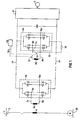
- the motor 2 is driven from the contact wire 1 during driving operation (FIG. 1) a locomotive is supplied with electrical energy.
- a locomotive is supplied with electrical energy.
- the pantograph 3, which is assigned to the contact wire 1 and the rail 20 is the primary winding 5 of a transformer connected.
- Secondary windings 6a to 6n of this transformer are on two lines 7a to 7n and 8a to 8n with line rectifier modules 4a to 4n, of which only two are shown, on a first 9a to 9n and on one second connection 10a to 10n in connection. All rectifier modules 4a to 4n are connected via an intermediate circuit with a machine-side inverter 21 connected to the motor 2 is connected.
- a line-side rectifier module 4n On a line-side rectifier module 4n is in the first Line 7n arranged a first switch 12 through which the Connection of the secondary winding 6n of the transformer with the rectifier module 4n can be interrupted.
- the first connection 9n of the rectifier module on the line side 4n stands over a connecting line 13 in which a second Switch 14 is arranged with a braking resistor 15 in Connection.
- the switches 12, 14 are connected via switching lines 18 to a Device 19 for triggering the braking operation connected to the can be a brake lever in the cab of the locomotive.
Landscapes
- Engineering & Computer Science (AREA)
- Power Engineering (AREA)
- Transportation (AREA)
- Mechanical Engineering (AREA)
- Electric Propulsion And Braking For Vehicles (AREA)
Abstract
Description
Claims (4)
- Vom Netz unabhängige elektrische Bremse für eine von einem Elektromotor (2) angetriebene Lokomotive mit einem Bremswiderstand (15), der beim Bremsen vom Elektromotor (2) erzeugte elektrische Energie in Wärme umwandelt, und mit einem netzseitigen Gleichrichtermodul (4n),
dadurch gekennzeichnet, dass der Bremswiderstand (15) über Schalter (12, 14), mit dem netzseitigen Gleichrichtermodul (4n) verbunden ist. - Bremse nach Anspruch 1,
dadurch gekennzeichnet, dass die Schalter (12, 14) über Schaltleitungen (18) mit einer Vorrichtung (19) zum Auslösen des Bremsbetriebs verbunden sind. - Bremse nach einem der Ansprüche 1 oder 2, wobei ein netzseitig dem Gleichrichtermodul (4n) vorgeschalteter Transformator über Leitungen (7n und 8n) mit einem ersten (9n) und einem zweiten Anschluss (10n) des Gleichrichtermoduls (4n) verbunden ist,
dadurch gekennzeichnet, dass in der Leitung (7n) ein erster Schalter (12) angeordnet ist und dass der erste Anschluss (9n) über einen zweiten Schalter (14) mit dem Bremswiderstand (15) verbunden sind. - Bremse nach Anspruch 3,
dadurch gekennzeichnet, dass beim Fahren der erste Schalter (12) geschlossen und der zweite Schalter (14) offen ist und dass beim Bremsen der erste Schalter (12) offen und der zweite Schalter (14) geschlossen ist.
Applications Claiming Priority (2)
| Application Number | Priority Date | Filing Date | Title |
|---|---|---|---|
| DE10114100 | 2001-03-22 | ||
| DE2001114100 DE10114100A1 (de) | 2001-03-22 | 2001-03-22 | Vom Netz unabhängige elekrische Bremse für eine Lokomotive |
Publications (2)
| Publication Number | Publication Date |
|---|---|
| EP1243459A2 true EP1243459A2 (de) | 2002-09-25 |
| EP1243459A3 EP1243459A3 (de) | 2003-11-26 |
Family
ID=7678604
Family Applications (1)
| Application Number | Title | Priority Date | Filing Date |
|---|---|---|---|
| EP02005533A Ceased EP1243459A3 (de) | 2001-03-22 | 2002-03-11 | Vom Netz unabhängige elektrische Bremse für eine Lokomotive |
Country Status (2)
| Country | Link |
|---|---|
| EP (1) | EP1243459A3 (de) |
| DE (1) | DE10114100A1 (de) |
Cited By (1)
| Publication number | Priority date | Publication date | Assignee | Title |
|---|---|---|---|---|
| CN102582446A (zh) * | 2012-03-09 | 2012-07-18 | 上海三一重机有限公司 | 一种用于电阻栅冷却风机的宽电压输入切换电路 |
Citations (1)
| Publication number | Priority date | Publication date | Assignee | Title |
|---|---|---|---|---|
| DE3447570C1 (de) | 1984-12-21 | 1986-08-21 | Licentia Patent-Verwaltungs-Gmbh, 6000 Frankfurt | Verfahren zur netzunabhängigen Widerstandsbremsung einer über eine löschbare Brückenschaltung gespeisten Asynchronmaschine |
Family Cites Families (1)
| Publication number | Priority date | Publication date | Assignee | Title |
|---|---|---|---|---|
| DE2919530C2 (de) * | 1979-05-11 | 1983-05-26 | Licentia Patent-Verwaltungs-Gmbh, 6000 Frankfurt | Anordnung für netzunabhängiges Widerstandsbremsen elektrischer Triebfahrzeuge |
-
2001
- 2001-03-22 DE DE2001114100 patent/DE10114100A1/de not_active Withdrawn
-
2002
- 2002-03-11 EP EP02005533A patent/EP1243459A3/de not_active Ceased
Patent Citations (1)
| Publication number | Priority date | Publication date | Assignee | Title |
|---|---|---|---|---|
| DE3447570C1 (de) | 1984-12-21 | 1986-08-21 | Licentia Patent-Verwaltungs-Gmbh, 6000 Frankfurt | Verfahren zur netzunabhängigen Widerstandsbremsung einer über eine löschbare Brückenschaltung gespeisten Asynchronmaschine |
Non-Patent Citations (1)
| Title |
|---|
| GAMMERT R: "DIE ELEKTRISCHE AUSRUESTUNG DER DREHSTROMLOKOMOTIVE BAUREIHE 120 DER DEUTSCHEN BUNDESBAHN", ELEKTRISCHE BAHNEN, OLDENBOURG INDUSTRIEVERLAG, MUNCHEN, DE, vol. 77, no. 10, 1 January 1979 (1979-01-01), pages 272 - 283, XP008049235, ISSN: 0013-5437 * |
Cited By (1)
| Publication number | Priority date | Publication date | Assignee | Title |
|---|---|---|---|---|
| CN102582446A (zh) * | 2012-03-09 | 2012-07-18 | 上海三一重机有限公司 | 一种用于电阻栅冷却风机的宽电压输入切换电路 |
Also Published As
| Publication number | Publication date |
|---|---|
| EP1243459A3 (de) | 2003-11-26 |
| DE10114100A1 (de) | 2002-10-02 |
Similar Documents
| Publication | Publication Date | Title |
|---|---|---|
| EP2396188B1 (de) | Anordnung zum betreiben von verbrauchern in einem schienenfahrzeug mit elektrischer energie, wahlweise aus einem energieversorgungsnetz oder aus einer motor-generator-kombination | |
| DE69310311T2 (de) | Steuervorrichtung für elektrisches Fahrzeug | |
| DE102012223901B4 (de) | Stromversorgungseinrichtung für ein Schienenfahrzeug | |
| WO1993001650A1 (de) | Verfahren und vorrichtung zum betrieb eines wechselrichters eines drehstromantriebs eines elektroautos als bordladegerät | |
| AT500328A1 (de) | Fahrzeug mit batteriefahrt und verfahren zum betrieb eines solchen fahrzeuges | |
| DE19742623C2 (de) | Betriebsverfahren für ein Stromversorgungssystem eines Mehrsystem-Schienenfahzeugs und Stromversorgungssystem eines Mehrsystem-Schienenfahzeugs | |
| DE69420665T3 (de) | Steuerungsvorrichtung für Elektrofahrzeuge | |
| EP0833758B1 (de) | Verfahren und schaltung zur umformung elektrischer energie | |
| EP2559587B1 (de) | Umrichter zum Betreiben eines elektrischen Antriebsmotors eines Elektrofahrzeugs, Kraftwagen und Verfahren zum Betreiben des Umrichters | |
| EP0670236A1 (de) | Energieversorgungseinrichtung für Reisezugwagen | |
| DE19908495B4 (de) | Von einem AC-Fahrdraht versorgte, tranformatorlose Einspeiseschaltung für eine Wechselstrommaschine eines Bahnfahrzeuges | |
| EP0543203B1 (de) | Verfahren und Schaltung zur Umformung elektrischer Energie | |
| EP1243459A2 (de) | Vom Netz unabhängige elektrische Bremse für eine Lokomotive | |
| DE102015205846B4 (de) | Antriebssystem | |
| EP0207280B1 (de) | Einrichtung zur Energieversorgung eines Reisezugwagens mit Wirbelstrombremsen | |
| EP0514580A1 (de) | Umrichteranordnung | |
| DE2336568A1 (de) | Umschaltanordnung fuer das arbeiten von elektrischen maschinen als motoren oder als generatoren mit nutzbremsung mit parallel- oder reihenschaltung der anker | |
| DE3044238C2 (de) | Schalteinrichtung für Gleichstrombremsung von Asynchronmotoren | |
| WO2022037800A1 (de) | Dual-mode-lokomotive | |
| EP3184349A1 (de) | Energieversorgungssystem für ein fahrzeug und fahrzeug elektrischem traktionssystem | |
| DE3714186C2 (de) | ||
| DE3347746A1 (de) | Anordnung zur versorgung von teilbordnetzen auf triebfahrzeugen elektrischer bahnen | |
| DE4446778C2 (de) | Mittelfrequenz-Serienschwingkreis-Brückenwechselrichter zur Speisung eines Wechselspannungsbordnetzes | |
| DE664734C (de) | Bremsschaltung fuer einphasige Wechselstromkommutatormotoren | |
| EP3929019B1 (de) | Fahrzeug, insbesondere schienenfahrzeug mit traktions- und bordnetz |
Legal Events
| Date | Code | Title | Description |
|---|---|---|---|
| PUAI | Public reference made under article 153(3) epc to a published international application that has entered the european phase |
Free format text: ORIGINAL CODE: 0009012 |
|
| AK | Designated contracting states |
Kind code of ref document: A2 Designated state(s): AT BE CH CY DE DK ES FI FR GB GR IE IT LI LU MC NL PT SE TR |
|
| AX | Request for extension of the european patent |
Free format text: AL;LT;LV;MK;RO;SI |
|
| PUAL | Search report despatched |
Free format text: ORIGINAL CODE: 0009013 |
|
| AK | Designated contracting states |
Kind code of ref document: A3 Designated state(s): AT BE CH CY DE DK ES FI FR GB GR IE IT LI LU MC NL PT SE TR |
|
| AX | Request for extension of the european patent |
Extension state: AL LT LV MK RO SI |
|
| RIC1 | Information provided on ipc code assigned before grant |
Ipc: 7B 60L 7/02 B Ipc: 7B 60L 7/22 A |
|
| 17P | Request for examination filed |
Effective date: 20040405 |
|
| AKX | Designation fees paid |
Designated state(s): AT BE CH CY DE DK ES FI FR GB GR IE IT LI LU MC NL PT SE TR |
|
| 17Q | First examination report despatched |
Effective date: 20101027 |
|
| STAA | Information on the status of an ep patent application or granted ep patent |
Free format text: STATUS: THE APPLICATION HAS BEEN REFUSED |
|
| 18R | Application refused |
Effective date: 20120202 |