EP1243374A1 - Verfahren zum Herstellen einer Werkstückverbindung, insbesondere einer Verbindung einer Finnenaussenhaut mit einem Stringer - Google Patents
Verfahren zum Herstellen einer Werkstückverbindung, insbesondere einer Verbindung einer Finnenaussenhaut mit einem Stringer Download PDFInfo
- Publication number
- EP1243374A1 EP1243374A1 EP01103273A EP01103273A EP1243374A1 EP 1243374 A1 EP1243374 A1 EP 1243374A1 EP 01103273 A EP01103273 A EP 01103273A EP 01103273 A EP01103273 A EP 01103273A EP 1243374 A1 EP1243374 A1 EP 1243374A1
- Authority
- EP
- European Patent Office
- Prior art keywords
- sheet
- reinforcing part
- sheet metal
- metal cover
- infrared radiation
- Prior art date
- Legal status (The legal status is an assumption and is not a legal conclusion. Google has not performed a legal analysis and makes no representation as to the accuracy of the status listed.)
- Granted
Links
Images
Classifications
-
- B—PERFORMING OPERATIONS; TRANSPORTING
- B23—MACHINE TOOLS; METAL-WORKING NOT OTHERWISE PROVIDED FOR
- B23K—SOLDERING OR UNSOLDERING; WELDING; CLADDING OR PLATING BY SOLDERING OR WELDING; CUTTING BY APPLYING HEAT LOCALLY, e.g. FLAME CUTTING; WORKING BY LASER BEAM
- B23K1/00—Soldering, e.g. brazing, or unsoldering
- B23K1/005—Soldering by means of radiant energy
- B23K1/0053—Soldering by means of radiant energy soldering by means of infrared [IR]
-
- B—PERFORMING OPERATIONS; TRANSPORTING
- B32—LAYERED PRODUCTS
- B32B—LAYERED PRODUCTS, i.e. PRODUCTS BUILT-UP OF STRATA OF FLAT OR NON-FLAT, e.g. CELLULAR OR HONEYCOMB, FORM
- B32B15/00—Layered products comprising a layer of metal
- B32B15/04—Layered products comprising a layer of metal comprising metal as the main or only constituent of a layer, which is next to another layer of the same or of a different material
-
- B—PERFORMING OPERATIONS; TRANSPORTING
- B64—AIRCRAFT; AVIATION; COSMONAUTICS
- B64C—AEROPLANES; HELICOPTERS
- B64C1/00—Fuselages; Constructional features common to fuselages, wings, stabilising surfaces or the like
- B64C1/26—Attaching the wing or tail units or stabilising surfaces
-
- B—PERFORMING OPERATIONS; TRANSPORTING
- B64—AIRCRAFT; AVIATION; COSMONAUTICS
- B64F—GROUND OR AIRCRAFT-CARRIER-DECK INSTALLATIONS SPECIALLY ADAPTED FOR USE IN CONNECTION WITH AIRCRAFT; DESIGNING, MANUFACTURING, ASSEMBLING, CLEANING, MAINTAINING OR REPAIRING AIRCRAFT, NOT OTHERWISE PROVIDED FOR; HANDLING, TRANSPORTING, TESTING OR INSPECTING AIRCRAFT COMPONENTS, NOT OTHERWISE PROVIDED FOR
- B64F5/00—Designing, manufacturing, assembling, cleaning, maintaining or repairing aircraft, not otherwise provided for; Handling, transporting, testing or inspecting aircraft components, not otherwise provided for
- B64F5/10—Manufacturing or assembling aircraft, e.g. jigs therefor
Definitions
- the invention relates to a method for producing a workpiece connection and a workpiece arrangement with a workpiece connection that can be produced thereby.
- Such a workpiece arrangement can in particular be part of a fin Plane, in which a sheet of titanium serving as the outer surface or a titanium-containing alloy with an internal reinforcing part Titan, for example a stringer. Furthermore can also Workpieces made of another metal, such as aluminum, are connected according to the invention.
- connection is high loads during flight operations exposed.
- the components used, the fin outer sheet and the reinforcement part as small as possible, to a desired To be able to realize lightweight construction. Training a suitable one Connection is therefore problematic. Is the connection through a weld of the reinforcing part and the wing panel, this leads to Structural changes and a weakening of the wing panel. adhesive bonds do not keep the stress during flight operations was standing.
- a perforated sheet to reduce turbulent Currents on the outside of the sheet are in the joint area also closed the through holes. Therefore, the required Connection area should be as small as possible, which leads to the fact that in the Connection occurring voltages due to the small connection area are relatively large.
- the object of the invention is based on the prior art To create improvement and in particular a secure and firm connection between the sheet of titanium or a titanium-containing alloy and the reinforcing part to create from titanium or a titanium-containing alloy.
- the connection should advantageously be low-tension or tension-free and have little or no oxide inclusions.
- the process is said to continue can advantageously be carried out with relatively little effort and can be reproduced well his.
- the object is achieved by the metal sheet between at least two sheet metal cover molds largely made of one for infrared radiation permeable material is placed, a reinforcing part made of metal at least one reinforcement part is recorded, the sheet and the reinforcing part in a connection area provided with a solder pressed against each other, and from at least one infrared radiation source Infrared radiation via at least one sheet cover form on the sheet is irradiated.
- the reinforcing part receptacles can advantageously also be made from one material that is largely transparent to infrared radiation.
- the invention is based on the idea of enabling, on the one hand, a large-area, uniform force transmission to the sheet metal by means of transparent sheet metal cover molds, and on the other hand direct heating of a soldering area between the sheet metal and the reinforcing part.
- the energy supplied and absorbed by the infrared radiation is evenly dissipated to the two sides of the sheet by heat conduction and thermal radiation via the sheet metal cover molds, so that relatively low stresses occur due to temperature gradients.
- the sheet metal cover molds By choosing a glass material that is transparent to infrared radiation and has a relatively low thermal conductivity as the material of the sheet metal cover molds, a very low temperature gradient can be achieved in the sheet metal and the reinforcing part, so that relatively low stresses in the soldered connection area due to temperature gradients in the Manufacturing occur. Furthermore, due to the good thermal insulation, a relatively low radiation power from the infrared radiation sources is required. If the sheet metal is at least planar around the connection area, correspondingly flat sheet metal cover plates can be used. However, it is also possible to use sheets with a more complex shape by using appropriately adapted sheet metal cover molds which can be used repeatedly in the production of this connection arrangement.
- the sheet can in particular be used as an outer sheet of a fin Be titanium sheet.
- the reinforcing part can in particular be in the wing arranged stringer.
- a plan trained area of the Stringers together with correspondingly thick spacers between two as Stringer recordings serving glass plates are recorded with the glass plates serving as sheet metal receiving plates can be clamped.
- the stringer can advantageously be pressed against the sheet can also be generated by the weight of a stringer mounting plate, the covers the stringer upwards. In this case the stringer of attached to the top of the lying sheet.
- only one infrared radiation source can be used, which, for example, heats the sheet from one side.
- the resulting Temperature gradients in the sheet in the direction of sheet thickness and corresponding Temperature gradients in the connection area with the reinforcement part to reduce the infrared radiation from the side through the glass panes directly onto the connection area or advantageously by two or more infrared radiation sources that make up the connection arrangement from the two opposite sides of the sheet heat.
- a temperature gradient along the sheet thickness becomes small held or even eliminated, so that tension occurring during soldering are reduced.
- thermocouple can be used to read the temperature that along the sheet, for example in a recess one Cover plate extends and read at its end via a line becomes. Its signals can be read from outside via a cable.
- an edge of a sheet metal cover plate can do something beveled in order to free space for receiving the thermocouple create.
- other options are one Temperature determination, for example by means of an optical one Temperature reading through a transparent sheet metal cover, basically possible.
- connection area to be soldered according to the invention between the sheet metal cover molds and, if necessary, reinforcement part recordings largely airtight can be shielded
- the soldering can basically be done without use a protective gas, because only between the molds or plates remaining oxygen to oxidize the Solder contributes.
- a Shielding gas in particular argon.
- the outside is sealed by the sheet metal cover molds.
- the protective gas can thus pass through a separate feeder or fed through the channel and over the channel be dissipated or diffuse away from the solder joints.
- protective gas can also be supplied laterally from the sheet, for example and diffuse to the connection area.
- connection area can be generated according to the invention, in particular a perforated, for example microperforated, sheet is used become.
- the sheet metal cover molds can be used as guides for the Serve reinforcement to prevent sideways tilting.
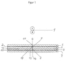
- a titanium sheet 2 serving as the outer sheet of a fin is connected to a stringer 3 made of titanium in a connection area 19 by an aluminum solder 7.
- the titanium sheet 2 is received or clamped between an upper sheet metal cover plate 5 and a lower sheet metal cover plate 6.
- the upper sheet metal cover plate 5 in the embodiment of FIG. 1 can be formed with a free space 11 in which a thermocouple 4 is provided.
- the stringer 3 has a vertical region 14 and an orthogonal thereto arranged horizontal area 15 on that of an upper stringer plate 8 and a lower stringer mounting plate 9, respectively is pinched.
- the vertical region 14 runs through the upper stringer mounting plate 8 and the lower metal cover plate 6.
- the aluminum solder 7 can in particular provided as aluminum foil at the end of the vertical region 14 become.
- an aluminum foil with a degree of purity of at least 99%, or another suitable aluminum foil can be used.
- An infrared radiation source in particular as an infrared light emitter infrared radiation emit in the short-wave infrared spectrum from 0.78 ⁇ m to 1.40 ⁇ m can be provided above the arrangement described.
- An infrared radiation becomes the connection area via the upper metal cover plate 5 fed.
- An aluminum reflector can continue between the glass plates 6 and 8 13 may be provided. This can cause heat radiation from the heated Sheet 2 is emitted, reflected back to the sheet, so that good heat insulation and even heating of the titanium sheet and the reinforcement area.
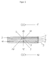
- a second infrared radiation source 12 is additionally used, which in particular can also be designed as an IR bright radiator.
- a channel 17 is also provided in the lower metal cover plate 6, in which a thermocouple 4 is provided.
- Shielding gas can be supplied and discharged through the channel 17.
- This channel can be connected directly to an inert gas source so that it shielding gas flows evenly.
- the lower sheet metal cover plate 6 can in particular be formed in two parts and release channel 17 between the two parts.
- an intermediate plate 16 designed as a glass plate below the lower sheet metal cover plate be provided to close the channel down.
- the radiant power of the Infrared source 1 or the two infrared sources 1 and 12 is in Depends on the measured temperature, so that a uniform Temperature of for example 650-750 degrees Celsius is reached, too leads a secure solder connection in the connection area 19.
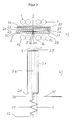
- Figures 3 a, 3 b show a further embodiment.
- the stringer is designed, for example, as an elongated plate and, according to FIG.
- a lower sheet metal cover plate 28 is provided below the sheet 2
- the upper sheet 2 is covered by two upper sheet metal cover plates 27 which accommodate the stringer 3 between them.
- two sheet metal cover plates 26 and 25 can rest on the sheet metal cover plate 27 and form a guide for the stringer 3.
- the sheet metal cover plates 25, 26, 27 are delimited by side plates 21 which are fastened to the lower sheet metal cover plate 28 by means of heat-resistant adhesive 22.
- a reinforcing part receiving plate 24 rests on the stringer 3. It is advantageously inserted precisely between the side plates 21.
- All plates 25, 26, 27, 28, 21, 24 are made of a material transparent to infrared radiation, in particular glass material.
- a furnace is thus formed from material which is transparent to infrared radiation.
- the reinforcing member receiving plate 24 Since the reinforcing member receiving plate 24 is only from the side plates 21 is guided, it presses the stringer 3 with its weight against the sheet 2, so that a sufficient contact pressure is achieved. This contact pressure can if necessary, by external stamps passing the infrared emitters be led, strengthened. Infrared radiation is on top Infrared radiation sources 1 and lower infrared radiation sources 12 evenly and fed symmetrically.
- Shielding gas can be directly in a free space 34 or via feed channels 35 that are on the side are formed next to the sheet 2, are supplied.
- This protective gas may be argon, in particular, which is heavier than that remaining in the array Air, especially oxygen.
- the protective gas can through the diffuse arrangement shown. It reaches the connection area 19, in the aluminum solder is provided.
- the protective gas can then be between diffuse the stringer 3 and the sheet metal cover plates 27, 26, 25 upwards. Since the reinforcing part mounting plate or stringer mounting plate 24 is free the stringer 3 rests, a space 23 remains between the stringer cover plate 24 and the sheet metal cover plate 25, which is used to discharge the protective gas can be used.
- Protective gas outlet pipe 29 may be provided, which may have a pressure relief valve can be trained.
- the protective gas can also be easily Lift off the stringer mounting plate 24 or go up to the side the stringer plate 24 diffuse upwards. In this case the protective gas outlet pipe 26 with pressure relief valve only as a safety measure serve.
- the protective gas can be supplied via a Gas inlet 32, a heating coil 31 made of copper, for example, and a Gas connector 30, which in particular as a hot gas connector Quartz glass can be formed.
- the heating of the heating coil can this is done using the infrared emitters.
- By feeding the warmed Shielding gas are preferably in addition to the two-sided and full surface irradiation of the temperature gradient is reduced or avoided.
- thermocouple 20 can be in the immediate vicinity of the connection area be provided in the free space 34.
- One of the Sheet metal cover plates 27 be slightly chamfered at their lower edge and the Leave free space 34 with, for example, a triangular cross section.
- the thermocouple 20 is received, which is a desired length of the sheet 2 and the stringer 3 can extend.
- the Reading is carried out according to Figure 3 b via a guided from the arrangement Line 33.
- all surfaces can be flushed with protective gas and so tarnishing colors can be avoided. It is a bracing of all parts possible so that when soldering the parts are kept in the intended shape become.
- the assembly can be done in the oven open from above before the soldering process respectively.
Landscapes
- Engineering & Computer Science (AREA)
- Mechanical Engineering (AREA)
- Aviation & Aerospace Engineering (AREA)
- Manufacturing & Machinery (AREA)
- Transportation (AREA)
- Laminated Bodies (AREA)
- Photometry And Measurement Of Optical Pulse Characteristics (AREA)
Abstract
Description
Wenn das Blech zumindest um den Verbindungsbereich herum plan ausgebildet ist, können entsprechend plane Blechabdeckplatten verwendet werden. Es ist jedoch auch eine Verwendung von Blechen mit komplexerer Formgebung möglich, indem entsprechend angepasste Blechabdeckformen verwendet werden, die bei der Produktion dieser Verbindungsanordnung wiederholt verwendet werden können.
- Figur 1
- einen Schnitt durch eine Vorrichtung zum Durchführen eines Verfahrens gemäß einer ersten Ausführungsform der Erfindung;
- Figur 2
- einen entsprechenden Schnitt durch eine Vorrichtung zum Durchführen eines Verfahrens gemäß einer weiteren Ausführungsform der Erfindung.
- Figur 3 a, b
- einen Schnitt und eine Draufsicht auf eine Vorrichtung zum Durchführen eines Verfahrens gemäß einer weiteren Ausführungsform der Erfindung.
- 1.
- Infrarot-Strahler
- 2.
- Titanblech
- 3.
- Stringer
- 4.
- Thermoelement
- 5.
- obere Blechabdeckplatte
- 6.
- untere Blechabdeckplatte
- 7.
- Lot
- 8.
- obere Stringeraufnahmeplatte
- 9.
- untere Stringeraufnahmeplatte
- 10.
- Distanzblech
- 11.
- Freiraum
- 12.
- Infrarot-Strahler
- 13.
- Reflektor
- 14.
- vertikaler Bereich
- 15.
- horizontaler Bereich
- 16.
- Zwischenplatte
- 17.
- Kanal
- 18. 19.
- Verbindungsbereich
- 20.
- Thermoelement
- 21.
- seitliche Platten
- 22.
- wärmebeständiger Klebstoff
- 23.
- Spalt
- 24.
- Verstärkungsteilaufnahme
- 25.
- Blechabdeckplatten
- 26.
- Blechabdeckplatten
- 27.
- Blechabdeckplatten
- 28.
- untere Blechabdeckplatten
- 29.
- Schutzgasauslassrohr
- 30.
- Anschlussstück
- 31.
- Heizspirale
- 32.
- Gaseinlass
- 33.
- Anschlussleitung für Thermoelement
- 34.
- Freiraum
- 35.
- Zuführkanal
Claims (24)
- Verfahren zum Herstellen einer Werkstückverbindung, insbesondere einer Verbindung eines Finnenaußenblechs mit einem Stringer, bei dem
ein Blech (2) aus einem Metall zwischen mindestens zwei Blechabdeckformen (5, 6; 27,28) aus einem für Infrarot-Strahlung weitgehend durchlässigen Material gelegt wird,
ein Verstärkungsteil (3) aus einem Metall von mindestens einer Verstärkungsteilaufnahme (8, 9; 24) aufgenommen wird,
das Blech und das Verstärkungsteil (3) in einem mit einem Lot (7) versehenen Verbindungsbereich (19) gegeneinander gedrückt werden, und
von mindestens einer Infrarot-Strahlungsquelle (1, 12) Infrarot-Strahlung über zumindest eine Blechabdeckform (5, 6) auf das Blech (2) eingestrahlt wird. - Verfahren nach Anspruch 1,
dadurch gekennzeichnet, dass auch die Verstärkungsteilaufnahme (8, 9; 24) aus einem für Infrarot-Strahlung weitgehend durchlässigen Material hergestellt ist. - Verfahren nach Anspruch 1 oder 2,
dadurch gekennzeichnet, dass das Metall des Bleches und des Verstärkungsteils Titan oder eine titanhaltige Legierung ist. - Verfahren nach Anspruch 3,
dadurch gekennzeichnet, dass das Lot ein Aluminium-Lot (7), vorzugsweise eine Aluminium-Folie mit mindestens 99 % Aluminium, ist. - Verfahren nach einem der vorherigen Ansprüche,
dadurch gekennzeichnet, dass das für Infrarot-Strahlung weitgehend durchlässige Material der Blechabdeckformen (5,6;25,26,27,28), vorzugsweise auch der Verstärkungsteilaufnahmen (8, 9;24), ein Glasmaterial ist. - Verfahren nach einem der vorherigen Ansprüche,
dadurch gekennzeichnet, dass von einer oder mehreren Infrarot-Strahlungsquellen Infrarot-Strahlung aus einer seitlichen Richtung zwischen das Blech (2) und das Verstärkungsteil (3), vorzugsweise direkt auf den Verbindungsbereich (19), eingestrahlt wird. - Verfahren nach einem der vorherigen Ansprüche,
dadurch gekennzeichnet, dass das Blech (2) zumindest um den Verbindungsbereich (19) herum plan ausgebildet ist und die Blechabdeckformen als plane Blechabdeckplatten (5, 6; 27,28) ausgebildet sind. - Verfahren nach einem der vorherigen Ansprüche,
dadurch gekennzeichnet, dass das Verstärkungsteil zwischen mindestens zwei Verstärkungsteilaufnahmen (8,9) aufgenommen ist. - Verfahren nach Anspruch 8,
dadurch gekennzeichnet, dass die Verstärkungsteilaufnahmen als plane Verstärkungsteilaufnahmeplatten (8, 9) ausgebildet sind, die ein planen Verstärkungsteilbereich (15) des Verstärkungsteils (3) und ein oder mehrere Distanzbleche (10) zwischen sich aufnehmen. - Verfahren nach einem der vorherigen Ansprüche,
dadurch gekennzeichnet, dass in zumindest einer Blechaufnahmeform (6) ein Kanal (17) zur Zuführung und Abführung eines Schutzgases, vorzugsweise Argon, zu dem Verbindungsbereich (19) ausgebildet ist. - Verfahren nach Anspruch 10
dadurch gekennzeichnet, dass eine untere Blechabdeckform (6) zweiteilig ausgebildet ist und den Kanal (17) frei lässt. - Verfahren nach einem der vorherigen Ansprüche,
dadurch gekennzeichnet, dass eine Verstärkungsteilaufnahme (24) gegen ein Ende des Verstärkungsteils (3) drückt und zwischen der Verstärkungsteilaufnahme (24) und einer Blechabdeckform (25,26,27) ein Zwischenraum (23) zur Abführung eines Schutzgases vorgesehen ist. - Verfahren nach Anspruch 12,
dadurch gekennzeichnet, dass seitliche Führungen, vorzugsweise seitliche Platten (21) aus einem für Infrarot-Strahlung durchlässigen Material, zur Aufnahme der Blechabdeckform (25,26,27) und der Verstärkungsteilaufnahme (24) vorgesehen sind. - Verfahren nach Anspruch 13,
dadurch gekennzeichnet, dass die seitlichen Führungen (21) den Zwischenraum (23) seitlich abgrenzen. - Verfahren nach einem der vorherigen Ansprüche,
dadurch gekennzeichnet, dass die Blechabdeckform mehrere übereinandergelegte Blechabdeckplatten (25,26,27) aufweist. - Verfahren nach einem der vorherigen Ansprüche,
dadurch gekennzeichnet, dass ein Anpressdruck des Verstärkungsteils (3) gegen das Blech (2) durch die Gewichtskraft einer Verstärkungsteilaufnahme (24) erzeugt wird. - Verfahren nach einem der Ansprüche 1 bis 15,
dadurch gekennzeichnet, dass ein Anpressdruck des Verstärkungsteils (3) gegen das Blech (2) durch Verspannen einer Verstärkungsteilaufnahme (9) gegen eine Blechabdeckform (5) erzeugt wird. - Verfahren nach einem der vorherigen Ansprüche,
dadurch gekennzeichnet, dass eine Temperatur des Bleches (2) und/oder des Verstärkungsteils (3) im Verbindungsbereich gemessen wird. - Verfahren nach Anspruch 18,
dadurch gekennzeichnet, dass ein Thermoelement (20) verwendet wird, das über eine Leitung (33) ausgelesen wird. - Verfahren nach Anspruch 18 oder 19,
dadurch gekennzeichnet, dass eine Intensität der eingestrahlten Infrarot-Strahlung in Abhängigkeit von der gemessenen Temperatur geregelt wird. - Verfahren nach einem der vorherigen Ansprüche,
dadurch gekennzeichnet, dass das Blech perforiert, vorzugsweise mikroperforiert, ist. - Verfahren nach einem der vorherigen Ansprüche,
dadurch gekennzeichnet, dass das Blech ein Außenblech (2) einer Finne eines Flugzeuges oder ein Tragflächenblech eines Flugzeuges, und das Verstärkungsteil ein Stringer (3) ist. - Werkstückanordnung, insbesondere als Teil einer Finne, mit einer Werkstückverbindung, die durch ein Verfahren nach einem der vorherigen Ansprüche herstellbar ist.
- Vorrichtung zum Durchführen eines Verfahrens nach einem der Ansprüche 1 bis 22.
Priority Applications (2)
| Application Number | Priority Date | Filing Date | Title |
|---|---|---|---|
| EP01103273A EP1243374B1 (de) | 2001-02-13 | 2001-02-13 | Verfahren zum Herstellen einer Werkstückverbindung, insbesondere einer Verbindung einer Finnenaussenhaut mit einem Stringer |
| DE50113472T DE50113472D1 (de) | 2001-02-13 | 2001-02-13 | Verfahren zum Herstellen einer Werkstückverbindung, insbesondere einer Verbindung einer Finnenaussenhaut mit einem Stringer |
Applications Claiming Priority (1)
| Application Number | Priority Date | Filing Date | Title |
|---|---|---|---|
| EP01103273A EP1243374B1 (de) | 2001-02-13 | 2001-02-13 | Verfahren zum Herstellen einer Werkstückverbindung, insbesondere einer Verbindung einer Finnenaussenhaut mit einem Stringer |
Publications (2)
| Publication Number | Publication Date |
|---|---|
| EP1243374A1 true EP1243374A1 (de) | 2002-09-25 |
| EP1243374B1 EP1243374B1 (de) | 2008-01-09 |
Family
ID=8176469
Family Applications (1)
| Application Number | Title | Priority Date | Filing Date |
|---|---|---|---|
| EP01103273A Expired - Lifetime EP1243374B1 (de) | 2001-02-13 | 2001-02-13 | Verfahren zum Herstellen einer Werkstückverbindung, insbesondere einer Verbindung einer Finnenaussenhaut mit einem Stringer |
Country Status (2)
| Country | Link |
|---|---|
| EP (1) | EP1243374B1 (de) |
| DE (1) | DE50113472D1 (de) |
Cited By (1)
| Publication number | Priority date | Publication date | Assignee | Title |
|---|---|---|---|---|
| CN1990149B (zh) * | 2005-12-30 | 2010-10-27 | 航天材料及工艺研究所 | 钛合金骨架与蒙皮变截面构件焊接方法 |
Citations (8)
| Publication number | Priority date | Publication date | Assignee | Title |
|---|---|---|---|---|
| EP0559035A1 (de) * | 1992-02-29 | 1993-09-08 | Saint Gobain Vitrage International | Lötverbindung zwischen einer auf einer Glasscheibe eingebrannten Leitmetallschicht und einem Stromanschlusselement |
| DE4424718A1 (de) * | 1994-07-13 | 1996-01-18 | Daimler Benz Aerospace Ag | Lot zum Löten von Aluminiumwerkstoffen |
| US5558304A (en) * | 1994-03-14 | 1996-09-24 | The B. F. Goodrich Company | Deicer assembly utilizing shaped memory metals |
| DE19536675C1 (de) * | 1995-09-30 | 1997-02-20 | Deutsche Forsch Luft Raumfahrt | Vorrichtung und Verfahren zur Herstellung von großflächigen Bauelementen nach dem RTM-Verfahren |
| US5841098A (en) * | 1996-09-27 | 1998-11-24 | Daimler-Benz Aerospace Airbus Gmbh | Method and apparatus for laser welding sectional members onto large-format aluminum structural components |
| JPH1147959A (ja) * | 1997-07-31 | 1999-02-23 | Mitsubishi Heavy Ind Ltd | 外板の製造方法 |
| DE19844035C1 (de) * | 1998-09-25 | 1999-11-25 | Daimler Chrysler Aerospace | Schalenbauteil für ein Flugzeug und Verfahren zur Herstellung |
| DE19924909C1 (de) * | 1999-05-31 | 2000-06-21 | Daimler Chrysler Ag | Metallisches Schalenbauteil |
-
2001
- 2001-02-13 EP EP01103273A patent/EP1243374B1/de not_active Expired - Lifetime
- 2001-02-13 DE DE50113472T patent/DE50113472D1/de not_active Expired - Fee Related
Patent Citations (8)
| Publication number | Priority date | Publication date | Assignee | Title |
|---|---|---|---|---|
| EP0559035A1 (de) * | 1992-02-29 | 1993-09-08 | Saint Gobain Vitrage International | Lötverbindung zwischen einer auf einer Glasscheibe eingebrannten Leitmetallschicht und einem Stromanschlusselement |
| US5558304A (en) * | 1994-03-14 | 1996-09-24 | The B. F. Goodrich Company | Deicer assembly utilizing shaped memory metals |
| DE4424718A1 (de) * | 1994-07-13 | 1996-01-18 | Daimler Benz Aerospace Ag | Lot zum Löten von Aluminiumwerkstoffen |
| DE19536675C1 (de) * | 1995-09-30 | 1997-02-20 | Deutsche Forsch Luft Raumfahrt | Vorrichtung und Verfahren zur Herstellung von großflächigen Bauelementen nach dem RTM-Verfahren |
| US5841098A (en) * | 1996-09-27 | 1998-11-24 | Daimler-Benz Aerospace Airbus Gmbh | Method and apparatus for laser welding sectional members onto large-format aluminum structural components |
| JPH1147959A (ja) * | 1997-07-31 | 1999-02-23 | Mitsubishi Heavy Ind Ltd | 外板の製造方法 |
| DE19844035C1 (de) * | 1998-09-25 | 1999-11-25 | Daimler Chrysler Aerospace | Schalenbauteil für ein Flugzeug und Verfahren zur Herstellung |
| DE19924909C1 (de) * | 1999-05-31 | 2000-06-21 | Daimler Chrysler Ag | Metallisches Schalenbauteil |
Non-Patent Citations (1)
| Title |
|---|
| PATENT ABSTRACTS OF JAPAN vol. 1999, no. 05 31 May 1999 (1999-05-31) * |
Cited By (1)
| Publication number | Priority date | Publication date | Assignee | Title |
|---|---|---|---|---|
| CN1990149B (zh) * | 2005-12-30 | 2010-10-27 | 航天材料及工艺研究所 | 钛合金骨架与蒙皮变截面构件焊接方法 |
Also Published As
| Publication number | Publication date |
|---|---|
| EP1243374B1 (de) | 2008-01-09 |
| DE50113472D1 (de) | 2008-02-21 |
Similar Documents
| Publication | Publication Date | Title |
|---|---|---|
| EP2200797B1 (de) | Verfahren zum herstellen eines faserverbundbauteils | |
| DE3423172C2 (de) | Verfahren zum Herstellen einer Solarbatterie | |
| EP2701190B1 (de) | Verfahren zur Herstellung eines Kühlkörpers für mindestens ein zu kühlendes Bauelement | |
| DE19511772C2 (de) | Vorrichtung und Verfahren zum Herstellen eines dreidimensionalen Objektes | |
| DE69305568T2 (de) | Verfahren zur Herstellung eines grossen, gewölbten Tanks | |
| EP3710234B1 (de) | Vorrichtung zum thermischen verschweissen von kunststoffteilen sowie anordnung enthaltend eine solche vorrichtung | |
| DE69007170T2 (de) | Verfahren zur Wärmebehandlung von Glasscheiben zum Härten der Randbereiche. | |
| WO2010000448A2 (de) | Vorrichtung zum schichtweisen herstellen eines dreidimensionalen objekts | |
| EP0061183B1 (de) | Verfahren zum Herstellen des festen Verbundes von Isolierglasscheiben | |
| DE19938807A1 (de) | Verfahren zur Formgebung von Glasteilen | |
| EP2859987B1 (de) | Bauteilverbund | |
| DE4233073A1 (de) | Verfahren zum Herstellen eines Halbleiter-Modulaufbaus | |
| WO2001087529A1 (de) | Verfahren zur herstellung eines bauelements aus übereinander gestapelten miteinander verlöteten platten | |
| EP1243374B1 (de) | Verfahren zum Herstellen einer Werkstückverbindung, insbesondere einer Verbindung einer Finnenaussenhaut mit einem Stringer | |
| DE2646845C3 (de) | Vorrichtung zum Biegen von Glasscheiben mit Hilfe von Preßwerkzeugen | |
| EP2289658A1 (de) | Verfahren und Vorrichtung zum Verlöten von Verbindungsleitern mit einer Solarzelle | |
| EP2295182B1 (de) | Lötverfahren für Wärmetauscher | |
| DE3030329C2 (de) | Sputterkörper | |
| DE60132614T2 (de) | Vorrichtung und verfahren zum fügenkleben zum festen zusammenfügen von metallischen blechen | |
| EP0259635B1 (de) | Verfahren zur Herstellung von thermisch hochbelasteten Kühlelementen | |
| EP3746413A1 (de) | Verfahren zur herstellung einer glasscheibe für vacuum-isolierglas | |
| DE3737565C2 (de) | ||
| DE1801195A1 (de) | Verfahren und Vorrichtung zur Verbindung laenglicher Metallteile mit Metallblech | |
| DE19623421C2 (de) | Vorrichtung, Lötschablone und Verfahren zum Löten von Temperaturwächtern | |
| DD252774A1 (de) | Vorrichtung und verfahren zum richten von gewoelbten blechflaechen |
Legal Events
| Date | Code | Title | Description |
|---|---|---|---|
| PUAI | Public reference made under article 153(3) epc to a published international application that has entered the european phase |
Free format text: ORIGINAL CODE: 0009012 |
|
| AK | Designated contracting states |
Kind code of ref document: A1 Designated state(s): AT BE CH CY DE DK ES FI FR GB GR IE IT LI LU MC NL PT SE TR |
|
| AX | Request for extension of the european patent |
Free format text: AL;LT;LV;MK;RO;SI |
|
| 17P | Request for examination filed |
Effective date: 20030114 |
|
| AKX | Designation fees paid |
Designated state(s): CH DE FR GB IT LI SE |
|
| RAP1 | Party data changed (applicant data changed or rights of an application transferred) |
Owner name: DEUTSCHES ZENTRUM FUER LUFT- UND RAUMFAHRT E.V. |
|
| 17Q | First examination report despatched |
Effective date: 20070322 |
|
| GRAP | Despatch of communication of intention to grant a patent |
Free format text: ORIGINAL CODE: EPIDOSNIGR1 |
|
| GRAS | Grant fee paid |
Free format text: ORIGINAL CODE: EPIDOSNIGR3 |
|
| GRAA | (expected) grant |
Free format text: ORIGINAL CODE: 0009210 |
|
| AK | Designated contracting states |
Kind code of ref document: B1 Designated state(s): CH DE FR GB IT LI SE |
|
| REG | Reference to a national code |
Ref country code: GB Ref legal event code: FG4D Free format text: NOT ENGLISH |
|
| REG | Reference to a national code |
Ref country code: CH Ref legal event code: EP |
|
| REF | Corresponds to: |
Ref document number: 50113472 Country of ref document: DE Date of ref document: 20080221 Kind code of ref document: P |
|
| REG | Reference to a national code |
Ref country code: CH Ref legal event code: NV Representative=s name: KELLER & PARTNER PATENTANWAELTE AG |
|
| REG | Reference to a national code |
Ref country code: SE Ref legal event code: TRGR |
|
| GBT | Gb: translation of ep patent filed (gb section 77(6)(a)/1977) |
Effective date: 20080405 |
|
| ET | Fr: translation filed | ||
| PLBE | No opposition filed within time limit |
Free format text: ORIGINAL CODE: 0009261 |
|
| STAA | Information on the status of an ep patent application or granted ep patent |
Free format text: STATUS: NO OPPOSITION FILED WITHIN TIME LIMIT |
|
| 26N | No opposition filed |
Effective date: 20081010 |
|
| PGFP | Annual fee paid to national office [announced via postgrant information from national office to epo] |
Ref country code: DE Payment date: 20090123 Year of fee payment: 9 |
|
| PGFP | Annual fee paid to national office [announced via postgrant information from national office to epo] |
Ref country code: CH Payment date: 20090223 Year of fee payment: 9 Ref country code: GB Payment date: 20090223 Year of fee payment: 9 |
|
| PGFP | Annual fee paid to national office [announced via postgrant information from national office to epo] |
Ref country code: IT Payment date: 20090226 Year of fee payment: 9 Ref country code: SE Payment date: 20090223 Year of fee payment: 9 |
|
| PGFP | Annual fee paid to national office [announced via postgrant information from national office to epo] |
Ref country code: FR Payment date: 20090217 Year of fee payment: 9 |
|
| REG | Reference to a national code |
Ref country code: CH Ref legal event code: PL |
|
| EUG | Se: european patent has lapsed | ||
| GBPC | Gb: european patent ceased through non-payment of renewal fee |
Effective date: 20100213 |
|
| PG25 | Lapsed in a contracting state [announced via postgrant information from national office to epo] |
Ref country code: CH Free format text: LAPSE BECAUSE OF NON-PAYMENT OF DUE FEES Effective date: 20100228 Ref country code: LI Free format text: LAPSE BECAUSE OF NON-PAYMENT OF DUE FEES Effective date: 20100228 |
|
| REG | Reference to a national code |
Ref country code: FR Ref legal event code: ST Effective date: 20101029 |
|
| PG25 | Lapsed in a contracting state [announced via postgrant information from national office to epo] |
Ref country code: FR Free format text: LAPSE BECAUSE OF NON-PAYMENT OF DUE FEES Effective date: 20100301 |
|
| PG25 | Lapsed in a contracting state [announced via postgrant information from national office to epo] |
Ref country code: DE Free format text: LAPSE BECAUSE OF NON-PAYMENT OF DUE FEES Effective date: 20100901 |
|
| PG25 | Lapsed in a contracting state [announced via postgrant information from national office to epo] |
Ref country code: IT Free format text: LAPSE BECAUSE OF NON-PAYMENT OF DUE FEES Effective date: 20100213 Ref country code: GB Free format text: LAPSE BECAUSE OF NON-PAYMENT OF DUE FEES Effective date: 20100213 |
|
| PG25 | Lapsed in a contracting state [announced via postgrant information from national office to epo] |
Ref country code: SE Free format text: LAPSE BECAUSE OF NON-PAYMENT OF DUE FEES Effective date: 20100214 |