EP1242205B1 - Vorbehandlung eines thixotropen metallbolzens - Google Patents
Vorbehandlung eines thixotropen metallbolzens Download PDFInfo
- Publication number
- EP1242205B1 EP1242205B1 EP00991167A EP00991167A EP1242205B1 EP 1242205 B1 EP1242205 B1 EP 1242205B1 EP 00991167 A EP00991167 A EP 00991167A EP 00991167 A EP00991167 A EP 00991167A EP 1242205 B1 EP1242205 B1 EP 1242205B1
- Authority
- EP
- European Patent Office
- Prior art keywords
- heating tube
- metal bolt
- bolt
- heating
- metal
- Prior art date
- Legal status (The legal status is an assumption and is not a legal conclusion. Google has not performed a legal analysis and makes no representation as to the accuracy of the status listed.)
- Expired - Lifetime
Links
- 229910052751 metal Inorganic materials 0.000 title claims abstract description 211
- 239000002184 metal Substances 0.000 title claims abstract description 210
- 230000009974 thixotropic effect Effects 0.000 title claims abstract description 93
- 238000002203 pretreatment Methods 0.000 title description 2
- 238000010438 heat treatment Methods 0.000 claims abstract description 271
- 238000000034 method Methods 0.000 claims abstract description 32
- 230000008569 process Effects 0.000 claims abstract description 22
- 229910010293 ceramic material Inorganic materials 0.000 claims abstract description 18
- 229910000831 Steel Inorganic materials 0.000 claims abstract description 11
- 239000007788 liquid Substances 0.000 claims abstract description 11
- 239000010959 steel Substances 0.000 claims abstract description 11
- 229910001338 liquidmetal Inorganic materials 0.000 claims description 26
- 230000006698 induction Effects 0.000 claims description 23
- 239000000463 material Substances 0.000 claims description 21
- 239000007787 solid Substances 0.000 claims description 14
- 229910000838 Al alloy Inorganic materials 0.000 claims description 13
- 238000004519 manufacturing process Methods 0.000 claims description 8
- 239000002245 particle Substances 0.000 claims description 6
- 239000010935 stainless steel Substances 0.000 claims description 6
- 229910001220 stainless steel Inorganic materials 0.000 claims description 6
- 210000001787 dendrite Anatomy 0.000 claims description 4
- 229910001315 Tool steel Inorganic materials 0.000 claims description 2
- 238000006073 displacement reaction Methods 0.000 claims 2
- 238000004220 aggregation Methods 0.000 claims 1
- 230000002776 aggregation Effects 0.000 claims 1
- 238000002347 injection Methods 0.000 claims 1
- 239000007924 injection Substances 0.000 claims 1
- 238000005266 casting Methods 0.000 abstract description 60
- 238000002360 preparation method Methods 0.000 abstract 1
- 229910052782 aluminium Inorganic materials 0.000 description 25
- XAGFODPZIPBFFR-UHFFFAOYSA-N aluminium Chemical compound [Al] XAGFODPZIPBFFR-UHFFFAOYSA-N 0.000 description 25
- 229910045601 alloy Inorganic materials 0.000 description 11
- 239000000956 alloy Substances 0.000 description 11
- 229910001092 metal group alloy Inorganic materials 0.000 description 9
- 238000009826 distribution Methods 0.000 description 7
- 238000007711 solidification Methods 0.000 description 7
- 230000008023 solidification Effects 0.000 description 7
- 238000012546 transfer Methods 0.000 description 6
- 230000008859 change Effects 0.000 description 5
- 230000001419 dependent effect Effects 0.000 description 5
- 238000004512 die casting Methods 0.000 description 5
- 150000002739 metals Chemical class 0.000 description 5
- 230000008018 melting Effects 0.000 description 4
- 238000002844 melting Methods 0.000 description 4
- 230000036962 time dependent Effects 0.000 description 4
- 229910018072 Al 2 O 3 Inorganic materials 0.000 description 3
- OKTJSMMVPCPJKN-UHFFFAOYSA-N Carbon Chemical compound [C] OKTJSMMVPCPJKN-UHFFFAOYSA-N 0.000 description 3
- 230000005496 eutectics Effects 0.000 description 3
- 238000003780 insertion Methods 0.000 description 3
- 230000037431 insertion Effects 0.000 description 3
- 238000005259 measurement Methods 0.000 description 3
- 239000000203 mixture Substances 0.000 description 3
- 230000003647 oxidation Effects 0.000 description 3
- 238000007254 oxidation reaction Methods 0.000 description 3
- RYGMFSIKBFXOCR-UHFFFAOYSA-N Copper Chemical compound [Cu] RYGMFSIKBFXOCR-UHFFFAOYSA-N 0.000 description 2
- FYYHWMGAXLPEAU-UHFFFAOYSA-N Magnesium Chemical compound [Mg] FYYHWMGAXLPEAU-UHFFFAOYSA-N 0.000 description 2
- HCHKCACWOHOZIP-UHFFFAOYSA-N Zinc Chemical compound [Zn] HCHKCACWOHOZIP-UHFFFAOYSA-N 0.000 description 2
- 230000015572 biosynthetic process Effects 0.000 description 2
- 239000003795 chemical substances by application Substances 0.000 description 2
- 239000004927 clay Substances 0.000 description 2
- 229910052802 copper Inorganic materials 0.000 description 2
- 239000010949 copper Substances 0.000 description 2
- 239000011521 glass Substances 0.000 description 2
- 230000001939 inductive effect Effects 0.000 description 2
- 238000009413 insulation Methods 0.000 description 2
- 229910052749 magnesium Inorganic materials 0.000 description 2
- 239000011777 magnesium Substances 0.000 description 2
- 230000014759 maintenance of location Effects 0.000 description 2
- 239000000155 melt Substances 0.000 description 2
- 238000000465 moulding Methods 0.000 description 2
- 239000011226 reinforced ceramic Substances 0.000 description 2
- 238000005204 segregation Methods 0.000 description 2
- 239000002002 slurry Substances 0.000 description 2
- 239000000126 substance Substances 0.000 description 2
- 238000012360 testing method Methods 0.000 description 2
- 238000010792 warming Methods 0.000 description 2
- 229910052725 zinc Inorganic materials 0.000 description 2
- 239000011701 zinc Substances 0.000 description 2
- PNEYBMLMFCGWSK-UHFFFAOYSA-N Alumina Chemical class [O-2].[O-2].[O-2].[Al+3].[Al+3] PNEYBMLMFCGWSK-UHFFFAOYSA-N 0.000 description 1
- 208000002599 Smear Layer Diseases 0.000 description 1
- RTAQQCXQSZGOHL-UHFFFAOYSA-N Titanium Chemical compound [Ti] RTAQQCXQSZGOHL-UHFFFAOYSA-N 0.000 description 1
- 229910052799 carbon Inorganic materials 0.000 description 1
- 239000004568 cement Substances 0.000 description 1
- 239000000919 ceramic Substances 0.000 description 1
- 239000007795 chemical reaction product Substances 0.000 description 1
- 238000009749 continuous casting Methods 0.000 description 1
- 238000001816 cooling Methods 0.000 description 1
- 239000013078 crystal Substances 0.000 description 1
- 238000005520 cutting process Methods 0.000 description 1
- 230000007547 defect Effects 0.000 description 1
- 238000000151 deposition Methods 0.000 description 1
- 238000013461 design Methods 0.000 description 1
- 238000011161 development Methods 0.000 description 1
- 230000018109 developmental process Effects 0.000 description 1
- 230000008030 elimination Effects 0.000 description 1
- 238000003379 elimination reaction Methods 0.000 description 1
- 239000000835 fiber Substances 0.000 description 1
- 239000012530 fluid Substances 0.000 description 1
- 239000000446 fuel Substances 0.000 description 1
- 229910002804 graphite Inorganic materials 0.000 description 1
- 239000010439 graphite Substances 0.000 description 1
- 239000003779 heat-resistant material Substances 0.000 description 1
- 239000012535 impurity Substances 0.000 description 1
- 230000003993 interaction Effects 0.000 description 1
- 230000001788 irregular Effects 0.000 description 1
- 239000010410 layer Substances 0.000 description 1
- 239000000314 lubricant Substances 0.000 description 1
- 239000011159 matrix material Substances 0.000 description 1
- QMQXDJATSGGYDR-UHFFFAOYSA-N methylidyneiron Chemical compound [C].[Fe] QMQXDJATSGGYDR-UHFFFAOYSA-N 0.000 description 1
- 229910052758 niobium Inorganic materials 0.000 description 1
- 239000010955 niobium Substances 0.000 description 1
- GUCVJGMIXFAOAE-UHFFFAOYSA-N niobium atom Chemical compound [Nb] GUCVJGMIXFAOAE-UHFFFAOYSA-N 0.000 description 1
- 230000035515 penetration Effects 0.000 description 1
- 239000011148 porous material Substances 0.000 description 1
- 238000004321 preservation Methods 0.000 description 1
- 230000002265 prevention Effects 0.000 description 1
- 238000012545 processing Methods 0.000 description 1
- 239000000047 product Substances 0.000 description 1
- 230000009467 reduction Effects 0.000 description 1
- 238000000926 separation method Methods 0.000 description 1
- 206010040560 shock Diseases 0.000 description 1
- 230000035939 shock Effects 0.000 description 1
- 239000006104 solid solution Substances 0.000 description 1
- 239000000243 solution Substances 0.000 description 1
- 238000003756 stirring Methods 0.000 description 1
- 230000007847 structural defect Effects 0.000 description 1
- 239000002344 surface layer Substances 0.000 description 1
- 229910052715 tantalum Inorganic materials 0.000 description 1
- GUVRBAGPIYLISA-UHFFFAOYSA-N tantalum atom Chemical compound [Ta] GUVRBAGPIYLISA-UHFFFAOYSA-N 0.000 description 1
- 239000010936 titanium Substances 0.000 description 1
- 229910052719 titanium Inorganic materials 0.000 description 1
- WFKWXMTUELFFGS-UHFFFAOYSA-N tungsten Chemical compound [W] WFKWXMTUELFFGS-UHFFFAOYSA-N 0.000 description 1
- 239000010937 tungsten Substances 0.000 description 1
- 229910052721 tungsten Inorganic materials 0.000 description 1
- 229910052720 vanadium Inorganic materials 0.000 description 1
- LEONUFNNVUYDNQ-UHFFFAOYSA-N vanadium atom Chemical compound [V] LEONUFNNVUYDNQ-UHFFFAOYSA-N 0.000 description 1
Images

Classifications
-
- B—PERFORMING OPERATIONS; TRANSPORTING
- B22—CASTING; POWDER METALLURGY
- B22D—CASTING OF METALS; CASTING OF OTHER SUBSTANCES BY THE SAME PROCESSES OR DEVICES
- B22D17/00—Pressure die casting or injection die casting, i.e. casting in which the metal is forced into a mould under high pressure
- B22D17/007—Semi-solid pressure die casting
-
- F—MECHANICAL ENGINEERING; LIGHTING; HEATING; WEAPONS; BLASTING
- F27—FURNACES; KILNS; OVENS; RETORTS
- F27B—FURNACES, KILNS, OVENS OR RETORTS IN GENERAL; OPEN SINTERING OR LIKE APPARATUS
- F27B17/00—Furnaces of a kind not covered by any of groups F27B1/00 - F27B15/00
- F27B17/0016—Chamber type furnaces
-
- F—MECHANICAL ENGINEERING; LIGHTING; HEATING; WEAPONS; BLASTING
- F27—FURNACES; KILNS; OVENS; RETORTS
- F27D—DETAILS OR ACCESSORIES OF FURNACES, KILNS, OVENS OR RETORTS, IN SO FAR AS THEY ARE OF KINDS OCCURRING IN MORE THAN ONE KIND OF FURNACE
- F27D3/00—Charging; Discharging; Manipulation of charge
- F27D2003/0034—Means for moving, conveying, transporting the charge in the furnace or in the charging facilities
- F27D2003/0075—Charging or discharging vertically, e.g. through a bottom opening
-
- F—MECHANICAL ENGINEERING; LIGHTING; HEATING; WEAPONS; BLASTING
- F27—FURNACES; KILNS; OVENS; RETORTS
- F27D—DETAILS OR ACCESSORIES OF FURNACES, KILNS, OVENS OR RETORTS, IN SO FAR AS THEY ARE OF KINDS OCCURRING IN MORE THAN ONE KIND OF FURNACE
- F27D3/00—Charging; Discharging; Manipulation of charge
-
- F—MECHANICAL ENGINEERING; LIGHTING; HEATING; WEAPONS; BLASTING
- F27—FURNACES; KILNS; OVENS; RETORTS
- F27D—DETAILS OR ACCESSORIES OF FURNACES, KILNS, OVENS OR RETORTS, IN SO FAR AS THEY ARE OF KINDS OCCURRING IN MORE THAN ONE KIND OF FURNACE
- F27D3/00—Charging; Discharging; Manipulation of charge
- F27D3/12—Travelling or movable supports or containers for the charge
Definitions
- the invention relates to a pretreatment device for providing a containing thixotropic metal bolt in a casting chamber of a thixoforming device a container for holding a metal bolt, an oven for Transfer of the metal bolt in the container into a partially liquid, thixotropic state, as well as a transport device for transporting and Insert the thixotropic metal bolt into the casting chamber, and use the pretreatment device.
- the invention further relates to a corresponding one Method according to the features of the preamble of claim 12, and the use of the procedure.
- Thixoforming concerns the production of molded parts from thixotropic metal bolts.
- metal bolts all bolts come from one into a thixotropic one Condition transferable metal in question.
- the metal bolts can be made of Aluminum, magnesium or zinc and the alloys of these metals exist.
- the thixotropic properties of a metal alloy mean that a suitably prepared metal is unloaded like a solid behaves, but reduces its viscosity so far under shear stress, that it is similar to a molten metal. This involves heating the Alloy in the solidification interval between liquidus and solidus temperature required. The temperature is to be set so that, for example, a structural component from 20 to 80% by weight is melted, but the rest in solid Shape remains.
- thixoforming With thixoforming, partially solid / partially liquid metal is used in a modified die casting machine, a so-called thixoforming device, processed into molded parts.
- the die casting machines used for thixoforming differ from each other die casting machines for die casting metal melts for example, a longer casting chamber to accommodate the thixotropic Metal pin and a larger piston stroke required thereby, and for example a mechanically reinforced design of the thixotropic metal alloy leading parts of the die casting machine due to the higher pressure load of these parts during thixoforming.
- the metal bolts are usually heated in a separate oven.
- the furnaces can be heated with fuel, such as gas or oil, or electrical energy, such as by means of a resistance heater or by means of inductive energy input.
- the metal bolt is brought into the thixotropic state, i.e. heating the bolt until the desired proportion of alloy has melted is expediently by an oven temperature controlled by sensors.
- a bowl Container for example in a metallic bowl made of stainless steel, or given a crucible made of clay graphite or clay SiC and in a horizontal position in transferred the thixotropic state.
- the thixotropic metal bolt can then, for example in the same container, by means of, for example, a gripper to the casting chamber of a horizontal thixoforming device transferred and introduced into the casting chamber by tilting the container become.
- the metal bolt remains during the heating process and transport to the casting chamber in the same container.
- EP-A-0 645 206 describes an apparatus for producing mechanical highly stressed parts by thixoforming, which is described at the beginning Contains pretreatment device.
- the metal bolts are cup-shaped Containers in a tubular continuous furnace in the thixotropic Condition transferred, and the container containing the thixotropic bolt is by means of transported to the casting chamber by a robot, and by tilting the container the thixotropic bolt is transported into the casting chamber.
- EP-B-0 713 736 describes a holding device for inductive heating of bolts made of metal alloys with thixotropic properties and for holding and transporting the bolts until they are cast.
- the holding device is there a specially designed trough-shaped bowl.
- the object of the present invention is to avoid the aforementioned disadvantages the prior art and the specification of a pretreatment device and a process for the reproducible provision of thixotropic metal bolts in a casting chamber of a thixoforming device, the thixotropic metal bolt a homogeneous temperature distribution and one over the entire bolt cross-section and the entire bolt length has a homogeneously distributed liquid portion, and the leakage of liquid metal into the heating furnace and the introduction of liquid metal in the casting chamber can be avoided.
- Another task at hand Invention is the preservation of the bolt shape during the heating process and the transport of the thixotropic bolt to and during the casting chamber Introduce into the casting chamber.
- Yet another object of the present invention is seen in the possibility of increasing the transport speed, because this means that during the bolt transport from the furnace to the casting chamber resulting cooling is reduced.
- the pretreatment device according to the invention is suitable for all metal bolts made of commercially available alloys which can be converted into a thixotropic state.
- Particularly suitable metal bolt materials are alloys made of aluminum, magnesium or zinc. In particular, cast aluminum and wrought aluminum alloys are preferred.
- the pretreatment device according to the invention is advantageously also suitable for processing particle-reinforced aluminum alloys which contain, for example, homogeneously distributed SiC or Al 2 O 3 particles.
- the pretreatment device according to the invention is very particularly suitable for aluminum alloys which have a pronounced solidification interval, such as AlSi7Mg.
- the metal bolts expediently contain homogeneously distributed, primarily solidified Solid particles consisting of individual degenerate dentrites. Prefers the proportion of primarily solidified solid particles is between 40 and 80% by weight. To achieve good thixotropic behavior, for example, aluminum alloys the alpha solid solution is available in globulistic form to a to achieve even flow of melt and solid.
- the degenerate dendrites of the metal bolts generally generally have one globulistic shape, resulting in a uniformly homogeneous flow of Melt and solid can be achieved without segregation.
- the production Metal bolts with a structure with globulistic dentrites are used, among other things. by a continuous casting process combined with an intense electromagnetic Stir also during the solidification phase. This leads to melting and breaking off dentrite arms that mold near the solidus temperature and form the globulistic structure.
- the metal bolts required for thixoforming become the thixoforming process by means of the pretreatment device according to the invention to a Temperature above the solidus temperature and below the liquidus temperature, i.e. heated until a partially solid, thixotropic state is reached.
- the semi-solid state contains the thixotropic alloy, the so-called thixotropic alloy Alloy slurry, the re-engineered dentritic, primary strength particles in one this surrounding matrix of liquid metal.
- the thixotrope preferably contains Alloy slurry has a liquid content of 40% by weight to 50% by weight and in particular between 43% and 48% by weight.
- the metal bolts can change with respect to their longitudinal axis are in a vertical or horizontal position.
- a is preferred Induction furnace used to convert the metal bolt into a thixotropic state.
- the alternating current flowing in the primary coil in the container and / or induces an alternating magnetic field in the metal bolt.
- the warming the heating tube or the metal bolt is done by the magnetic Alternating field, which has strong eddy currents in the heating pipe or in the metal bolt and thereby causes a corresponding warming.
- the depth of penetration the eddy currents and thus the depth of the heated layer is frequency-dependent; when using high frequencies, rapid heating predominantly takes place near-surface layers.
- this consists of a Metal.
- Metals from the iron-carbon-containing series are preferred for this purpose Metals such as steel, stainless steel, Thermax steel, hot work steel or out of line the metals tantalum, niobium, vanadium, tungsten or titanium or alloys thereof used.
- Heating tubes made of copper or its alloys are further preferred. Heating tubes made of steel and especially made of are particularly preferred Stainless steel or tool steel.
- a metal heating tube is used for the heating process in an induction furnace, in particular, a steel heating tube is used, so penetrates the magnetic Field essentially only the heating tube, so that the induction furnace in the essentially only the heating tube heats up directly and the heating of the metal bolt almost exclusively through heat conduction from the heating pipe into the metal bolts happens.
- the stud material is thus heated by heating the heating pipe and by conduction from the heating pipe to the stud material. Due to the high thermal conductivity of a metal heating tube radially symmetrical heat conduction from the heating pipe to the metal bolt, provided the metal bolt is in thermal contact over its entire circumference with the heating pipe. The radially symmetrical heat conduction then causes also a radially symmetrical temperature distribution in the metal bolt, whereby by the high thermal conductivity of the metal bolt very quickly becomes a minor radial Temperature gradient.
- the heating device according to the invention with a metal heating tube becomes a very homogeneous temperature and thus also a very homogeneous Liquid metal distribution achieved throughout the metal bolt. This especially because the direct energy input into the heating pipe and the stud material is only indirectly heated by heat conduction, so that any local existing differences in the structural structure or in the chemical composition the bolt material has no influence on the direct energy input to have.
- the heating tube this consist of ceramic material.
- the magnetic field penetrates the heating tube, i.e. the ceramic material of the heating tube is for the magnetic field transparent.
- the metal bolt is then heated by direct heating Interaction with the magnetic field of the induction furnace.
- Suitable ceramic materials are, for example, Al 2 O 3 , AL 3 O 4 , BN, SiC, Si 3 N 4 , MgO, TiO, ZrO 2 , stabilized, such as yttrium-stabilized ZrO 2 , glasses or refractory cements or mixtures, which the mentioned Materials included.
- the heating tube can consist of fiber-reinforced ceramic material or contain such materials, and the fibers of the fiber-reinforced ceramic material can be made of SiC, Al 2 O 3 , glass or carbon, for example.
- the inside diameter d R of the heating tube in the cold state is expediently somewhat larger than the bolt diameter d B of the cold metal bolt.
- the inner diameter d R of the heating tube as a function of the bolt diameter d B is preferably selected such that the metal bolt in the cold state, in particular at room temperature, ie at a temperature of 15 ° C. to 30 ° C., by a dimension ⁇ d of approximately 0.5 mm , preferably 0.5 ⁇ 0.3 mm, in particular 0.5 ⁇ 0.1 mm, is smaller than the inner diameter d R of the heating tube.
- the metal bolt expands in the radial and axial directions, so that at a certain point in time the bolt diameter d B corresponds to the inside diameter d R of the heating tube, it having to be taken into account that the inside diameter d R is also temperature-dependent.
- the material of the heating tube and the inside diameter d R of the heating tube are chosen such that the metal bolt at its solidus temperature T solidus has essentially the same diameter d B as the inside diameter d R of the heating tube.
- the bolt diameter d B at T solidus more preferably fulfills the relationship 0.996 d R ⁇ d B ⁇ d R , particularly preferably 0.998 d R d d B d d R and in particular 0.999 d R d d B d d R.
- the metal bolts are cylindrical and usually have a round or oval cross-section, but can also be polygonal cross-section.
- the diameter of the metal bolts in the cold state is, for example, 50 to 180 mm, expediently 75 to 150 mm and preferably 100 to 150 mm.
- the The length of the metal bolt is, for example, 80 to 500 mm when cold.
- the metal bolt heats up, the metal bolt and the heating tube expand.
- Different materials have different coefficients of thermal expansion.
- the thermal expansion coefficient of steel or ceramic material is significantly smaller than that of, for example, aluminum or aluminum alloys. Accordingly, a metal bolt made of an aluminum alloy, for example, expands more than a heating tube made of, for example, steel or ceramic material, so that - starting from a smaller diameter of the metal bolt in the cold state compared to the inner diameter of the heating tube - the metal bolt at a certain temperature has the same diameter as has the heating tube.
- the diameter of the metal stud essentially corresponds to the diameter of the heating pipe, so that in the temperature range in which the thixotropic properties of the metal stud are essentially set, optimal thermal contact between the heating pipe and the metal stud is formed.
- the heating tube containing the metal bolt is heated above the solidus temperature T solidus , the eutectic is melted, combined with an increase in volume of the metal bolt.
- the eutectic of aluminum alloys suitable for thixoforming typically forms at approximately 550 to 570 ° C.
- the volume increase in the range between solidus and liquidus temperature is typically approx.
- the stud material can only expand in the longitudinal direction of the heating tube, provided the condition according to which at T solidus Bolt diameter d B corresponds to the diameter d R of the heating pipe is fulfilled.
- T solidus Bolt diameter d B corresponds to the diameter d R of the heating pipe.
- the increase in volume between the solidus and liquidus state - depending on the bolt length - manifests itself in an increase in the bolt length of typically approx. 3 to 16 mm and in particular of 3 to 6 mm.
- the increase in length of an aluminum bolt below the solidus temperature is - depending on the bolt length - typically between 1 and 2 mm.
- the length of the heating tube must be in the cavity of the heating tube be longer than the bolt length.
- the length of the Heating tube selected such that the heating tube a total of about 5 to 30 mm, in particular 10 to 20 mm, is longer than the metal bolt to be heated therein.
- the wall thickness of the heating tube is preferably 1 to 5 mm for steel tubes, for Copper pipes preferably 4 to 10 mm and preferably 8 to 15 for ceramic pipes mm.
- the heating tube according to the invention can be closed on both sides.
- closure elements made of ceramic material.
- Materials for the closure elements are the same as described above Materials as for the one preferred variant of the heating tube made of ceramic material. Ceramic material points towards the metal stud material a low thermal conductivity, so that the radial temperature distribution at the front edge areas of the metal bolt through such closure elements is little influenced.
- the heating tube is expediently made of metal bolts on its two end faces by means of closure elements, preferably by plug or cone-shaped Closing elements, tightly closed.
- closure elements preferably by plug or cone-shaped Closing elements
- the stopper-shaped or peg-shaped closure elements are further preferred with regard to Material choice and shape designed such that their friction properties in the heating tube due to the thermal expansion of the metal bolt shift in the direction of the longitudinal axis during the heating process allow the heating tube and on the other hand a shift by the Metal bolts exerted pressure on the closure elements after reaching the the desired thixotropic state temperature is avoided.
- the closure elements Prior to the heating process, the closure elements are preferred so far pushed into the heating tube so that this is in direct mechanical contact the end faces of the metal bolt. This causes the locking elements to shift during the heating process in the heating tube due to the thermal Linear expansion of the metal bolt.
- the heating tube can do this with one end directly on a preferably height-adjustable table top, preferably on a table top made of ceramic material, or the heating tube can by means of a closure element, preferably by a plug or cone-shaped closure element, tightly closed and by means of this closure element on a preferably height-adjustable table top made of any heat-resistant material can be set in a vertical position.
- a stopper-shaped or peg-shaped closure element is the closure element with regard to choice of material and shape, preferably designed such that on the one hand no liquid metal is released during the heating process in the furnace can escape the heating tube and on the other hand the friction of the closure element is less than 10 N in the heating tube.
- the friction of the closure element must be low so that a gripper arm Transport device, in particular a robot gripper arm, the heating tube without great effort, i.e. without the gripper arm for large mechanical Stresses must be designed by the specified on the table top Closure element can lift off.
- a gripper arm Transport device in particular a robot gripper arm
- the heating tube without great effort, i.e. without the gripper arm for large mechanical Stresses must be designed by the specified on the table top Closure element can lift off.
- there is a high level of friction for achievement A high level of tightness is also not necessary because the closure element only prevent liquid metal from leaking during the heating process must and due to the cohesion of molten metals, in particular aluminum melts, this does not require a high level of tightness.
- the friction of the closure element in the heating tube is less than 30 N, preferably between 2 and 20 N and in particular between 5 and 10 N.
- the pretreatment device according to the invention is suitable for provision of a thixotropic metal bolt in a casting chamber of a vertical or Horizontal thixotropic molding.
- This pretreatment device is particularly advantageous however, for providing a thixotropic metal bolt in one horizontal casting chamber, since here the shape retention with the inventive Device can be guaranteed particularly well.
- a horizontal thixoforming device lies the casting chamber that holds the thixotropic metal bolt picks up, horizontally.
- the device according to the invention is particularly advantageous for the provision of thixotropic metal bolts made of aluminum or aluminum alloys.
- aluminum Billets are very particularly preferred in an induction furnace heated up in a vertical heating room.
- the heating tube containing the thixotropic metal bolt becomes after the heating process and after any draining from during the heating process Metal bolts that have leaked out, for example, by a robot Casting chamber transported and in the front, half-open part of the casting chamber inserted.
- the casting piston pushes the metal bolt out of the heating tube into one closed part of the casting chamber; then the thixotropic metal alloy through a through opening into the pouring channels and then into the mold cavity initiated.
- the casting piston is pulled back, see above that afterwards a gripper arm of the transport device removes the heating pipe from the Pick up the casting chamber and use it for further pretreatment processes can feed.
- the return of the heating pipe for further use for further pretreatment procedures expediently take place during the Solidification phase of the thixotropic metal alloy in the mold cavity. That while the solidification of the thixotropic metal alloy in the mold cavity Cast structure essentially determines the properties of the molded parts.
- the microstructure is characterized by phases such as mixed crystal and eutectic Phases, the cast grain, such as globulites and dendrites, segregations as well as structural defects such as porosity (gas pores, micro voids) and impurities, such as Oxides.
- the Liquid metal escaping from the metal bolt during the heating process at least partially removed from the heating tube.
- the one during the heating process Liquid metal portion emerging from the metal bolt is typically less than 1% by weight of the bolt material.
- the transport of the thixotropic metal bolt from the heating furnace into the casting chamber using a robot typically takes 5 to 30 s and preferably 8 to 15 s.
- the length of time that the thixotropic metal bolt remains in the casting chamber is typically between 3 and 5 s. This time is for driving away a robotic gripper arm from the casting chamber and for the electronic readiness control a thixoforming device is required.
- the pretreatment device according to the invention and the one according to the invention Methods are suitable for the provision of thixotropic metal bolts in vertical or horizontal casting chambers. Preferred uses of the invention Methods are described in the use claims 18 and 19.
- a circular cylinder is used to verify the heating principle in a heating pipe
- the aluminum bolt is located in a heating pipe during the heating process Stainless steel with a wall thickness of 5 mm.
- the heating pipe and thus the Metal bolts rest on a heat insulation plate at the lower end.
- the end of the heating tube protrudes about 5 mm from its circular top edge the upper edge of the bolt.
- the upper end of the heating pipe is not closed, so that the change in length using a laser interferometer during the whole heating process can be measured.
- thermocouples lying parallel to the longitudinal axis of the bolt, whereby - with respect to the concentric longitudinal axis of the aluminum bolt - a first thermocouple for measuring the edge temperature T 0 is introduced in the edge region of the aluminum bolt, a second thermocouple for measuring the temperature T. 1 is positioned in the middle between the center of the bolt and the edge of the bolt and a third thermocouple for measuring the temperature T 2 is arranged approximately 5 mm from the center of the bolt.
- the thermocouples are inserted approx. 50 mm deep into the bolt.
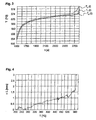
- the time-dependent temperature profiles T 0 (t), T 1 (t) and T 2 (t) measured with the three thermocouples mentioned are shown in FIG. 3 and - within a measurement accuracy of ⁇ 1% - all essentially show the same temperature profile.
- An aluminum bolt is used to investigate the dimensional stability of the thixotropic bolt
- the geometric shape of the thixotropic aluminum bolt shows that the Dimensional stability is given, i.e. the thixotropic aluminum bolt essentially has - apart from the thermal expansion - the same shape as the original Aluminum studs.
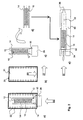
- FIG. 1 The drawings a) to c) of Fig. 1 each show a vertical longitudinal section along the concentric longitudinal axis l of a metal bolt 10, respectively. through the Device elements 14, 20, 30, in which the metal bolt 10 during the Pretreatment is, the heating process of the metal bolt 10 in one horizontal position happens.
- Fig. 1 a shows the loading of a in a solid physical state Metal bolt 10 in a horizontally lying heating pipe 14.
- the heating pipe 14 is closed with plug-shaped closure elements 16, 18, the Closure elements 16, 18 on the one hand on the end faces 15 of the heating tube 14 rest and on the other hand close flush with the metal bolt 10, i.e. the Closure elements 16, 18 lie within the heating tube 14 on the end faces 12 of the metal bolt 10.
- the heating tube 14 containing the metal bolt 10 and closed with the closure elements 16, 18 is inserted horizontally into the heating space 21 of an induction furnace 20.
- the heating tube 14 is located in the middle of the heating space 21 enclosed by induction coils 22, ie the concentric longitudinal axis of the heating space 21 and the concentric longitudinal axis l of the metal bolt 10 coincide.
- the metal bolt initially expands in all directions.
- T solidus solidus
- the metal bolt 10 abuts the heating tube 14, so that the metal bolt 10 essentially does not expand any further radially, ie the further radial expansion of the metal bolt 10 is due to the usually very small radial expansion of the heating tube 14 limited.
- the further thermal expansion of the metal bolt 10 after reaching the solidus temperature T solidus is essentially only possible in the direction of its concentric longitudinal axis l, the closure elements 16, 18 being pushed apart from one another in accordance with the thermal expansion of the metal bolt 10, so that the stopper-shaped closure elements 16, 18 no longer rest against the end faces 15 of the heating tube 14.
- Fig. 1 b shows the discharge of the induction furnace 20, i.e. bringing out the the thixotropic metal bolt 10 containing heating pipe 14 from the heating room 21 of the induction furnace 20.
- the closure elements 16, 18 are after the discharge of the induction furnace 20 separated from the heating tube 14.
- liquid molten metal 24 is removed from the heating tube 14 by removing the liquid Metal 24 can be drained from the heating tube 14, the liquid metal for example, is collected in a drip tray (not shown).
- FIG. 1 c) shows this in a casting chamber 30 of a horizontal thixoforming device introduced heating tube 14.
- the heating tube 14 is in the casting chamber cavity 32 of the casting chamber 30 positioned that during the subsequent Thixoform process of the casting piston 34 the thixotropic metal bolt 10 from the Heating pipe 14 can come across, so that the thixotropic metal alloy subsequently through the passage opening 36 into the sprue channels (not shown) and can then be introduced into the mold cavity (not shown).
- the casting chamber 30 has a recess for receiving the heating tube. This The recess serves on the one hand for centering the heating tube 14 and on the other hand as a stop for setting the heating tube 14 during ejection of the thixotropic metal bolt 10 at the beginning of the thixoforming process.
- FIG. 2 each show a vertical longitudinal section along the concentric longitudinal axis l of a metal bolt 10, respectively. through the Device elements 14, 20, 30, in which the metal bolt 10 during the Pretreatment is, the heating process of the metal bolt 10 in one vertical bolt position happens.
- FIG. 2 a shows the insertion of one located in a vertical heating tube 14
- Metal bolt 10 in a vertically lying, cylindrical heating chamber 21 of an induction furnace 20.
- the heating tube 14 is at the lower tube end, i.e. at the lower end face 15 of the heating tube 14, with a stopper-shaped closure element 16 closed.
- the closure element lies on a table top 26.
- the introduction of the heating tube 14 containing the metal bolt 10 into the induction furnace 20 is done by vertically placing the heating tube 14 on the table top 26, wherein the closure element 16 to lie on the table top 26 comes, and by lifting the table top 26 until the heating tube 14 completely comes to rest in the heating chamber 21 of the induction furnace 20.
- the heating pipe 14 is located in the middle of the heating space delimited by the induction coils 22 21, i.e. the concentric longitudinal axis of the heating space 21 coincides with the concentric Longitudinal axis l of the metal bolt 10 together.
- the metal bolt initially expands in the radial as well as in the vertical direction.
- the metal bolt 10 abuts the heating tube 14 in the radial direction, so that the metal bolt 10 essentially does not expand any further radially, ie the further radial expansion of the metal bolt 10 is due to the usually very small radial one Expansion of the heating tube 14 limited.
- the further thermal expansion of the metal bolt 10 after reaching the solidus temperature T solidus is essentially only possible in the vertical direction, parallel to its concentric longitudinal axis l.
- the upper tube end 15 of the heating tube 14 is open, so that the metal bolt 10 can expand thermally without hindrance.
- Fig. 2 b shows the induction furnace 20 after the heating tube 14 with the thixotropic metal bolt 10 is led out of the heating chamber 21.
- the leading out the thixotropic metal bolt is done by lowering the Table top 26.
- Fig. 2 c shows that led out of the furnace in the vertical direction thixotropic metal bolt 10 containing, fixed vertically on the table top 26 Heating tube 14, which also with the plug-shaped closure element 16 is tightly closed.
- FIG. 2 d shows that separated from the table top 26 and the closure element 16, the heating tube 14 containing the thixotropic metal bolt 10 in a horizontal manner Location.
- the heating tube 14 is expediently separated from the Closure element 16 and the transfer of the heating tube into a horizontal Position using a robot.
- the robot arm is used to lift the To heat up the heating tube 14 from the table top 26 and the closure element 16 Low power.
- the closure element 16 closes the heating tube 14 in a form-fitting manner tight.
- the tightness is only to avoid the outflow of liquid Metal required so that due to the surface tension of the liquid metal the closure element 16 essentially only in a form-fitting manner in the heating tube 14 must grip and therefore no high friction between the heating tube 14 and the closure element 16 is required.
- the thixotropic metal bolt is clamped in the heating tube in this way, i.e. whose Adhesion is so great that the heating tube in the vertical direction from the closure element can be lifted off without the thixotropic metal bolt 10 the heating tube 14 falls.
- the vertical lifting of the heating tube 14 from on the Table top 26 fixed closure element 16 also allows dripping of the liquid metal 24 formed during the heating process outside of the heating furnace 20.
- FIG. 2 e shows this in a casting chamber 30 of a horizontal thixoforming device introduced heating tube 14.
- the heating tube 14 is in the casting chamber cavity 32 of the casting chamber 30 positioned that during the subsequent Thixoform process of the casting piston 34 the thixotropic metal bolt 10 from the Heating pipe 14 can come across, so that the thixotropic metal alloy subsequently through the passage opening 36 into the sprue channels (not shown) and can then be introduced into the mold cavity (not shown).
- the casting chamber 30 has a recess for receiving the heating tube. This The recess serves on the one hand to center the heating tube 14 and on the other hand as a stop for setting the heating tube 14 during ejection of the thixotropic metal bolt 10 at the beginning of the thixoforming process.
- Inserting the thixotropic metal bolt 10 into the casting chamber cavity 32 the casting chamber 30 is expediently done by means of a robot.
- the The thixotropic metal bolt must be inserted so gently that the Shape retention of the bolt 10 guaranteed after insertion into the casting chamber 30 is.
- the heating curve shows a typical heating curve until the solidus temperature T solidus of an aluminum bolt 10 located in a heating pipe 14 according to the invention is reached in a resistance furnace.
- the heating curve relates to a circular cylindrical aluminum bolt 10 with a diameter of 100 mm and a length of 200 mm in a vertical position in a heating tube 14 made of stainless steel, the heating tube 14 having a wall thickness of 5 mm and the lower end face 12 of the aluminum bolt 10 a heat insulation plate 26 rests directly, ie the lower end face 12 of the aluminum bolt 10 and the lower end face 15 of the heating tube 14 lie in the same plane.
- the heating curve i.e. the time-dependent bolt temperature
- the heating curve is continuously recorded during the heating process by means of thermocouples lying parallel to the longitudinal axis l of the bolt, whereby - with respect to the concentric longitudinal axis l of the aluminum bolt 10 - a first thermocouple for measuring the edge temperature T 0 (t) in the edge area of the Aluminum bolt 10 is inserted, a second thermocouple for measuring the temperature T 1 (t) is positioned in the middle between the center of the bolt and the edge of the bolt and a third thermocouple for measuring the temperature T 2 (t) is arranged approximately 5 mm from the center of the bolt.
- the thermocouples are inserted approximately 50 mm deep into the bolt 10.
- the time-dependent temperature profiles T 0 (t), T 1 (t) and T 2 (t) measured with the three thermocouples mentioned are shown in FIG. 3 and - within a measurement accuracy of ⁇ 1% - all essentially show the same temperature profile.
- FIG. 4 shows an example of a typical temperature-dependent deformation curve during the heating process of an aluminum bolt 10 according to the invention, which is shown by the heating curve in FIG. 3. From FIG. 4 it can be seen that the aluminum bolt 10 is at approximately 560 ° until the solidus temperature T solidus is reached C extends in the longitudinal direction essentially linearly, depending on the temperature, by approx. 1.5 mm, the thermal linear expansion ⁇ L (T) increasing suddenly above the solidus temperature.
Landscapes
- Engineering & Computer Science (AREA)
- Mechanical Engineering (AREA)
- General Engineering & Computer Science (AREA)
- Furnace Details (AREA)
- Dowels (AREA)
- Heat Treatments In General, Especially Conveying And Cooling (AREA)
- Forging (AREA)
- Manufacture And Refinement Of Metals (AREA)
- Heat Treatment Of Articles (AREA)
- Coating With Molten Metal (AREA)
Description
- der Bolzenzustand, d.h. seine Teilfestigkeit, üblicherweise nur in einem kleinen Temperaturbereich vorhanden ist,
- lang dauernde Aufheizzeiten, beispielsweise der Bildung einer dicken Oxidhaut oder einer möglichen Kornvergröberung wegen, vermieden werden sollen,
- und zur Erzielung eines homogenen Endproduktes die Temperaturverteilung im thixotropen Metallbolzen, dem sogenannten Thixo-Rohling, möglichst homogen sein soll.
- garantiert eine homogene und symmetrische Erwärmung in achsialer und radialer Richtung des Bolzens;
- minimiert während dem Aufheizprozess in einem Induktionsofen die Inhomogenitäten des magnetischen Feldes an den Rändern des Bolzens;
- verhindert übermässiges Aufschmelzen der Bolzenoberfläche;
- gewährleistet den Formerhalt des Bolzens während dem Aufheizprozess, dem Transport zur Giesskammer und in der Giesskammer;
- beseitigt den Einfluss von allfällig vorhandenen, strukturellen Inhomogenitäten und der chemischen Zusammensetzung des Metallbolzens auf den Erwärmungsprozess;
- ermöglicht die Anwendung einer billigeren und effizienteren Erwärmung mittels Induktionsfeld mit einer gegenüber dem Stand der Technik höheren Frequenz;
- vermeidet - abgesehen vom Metallbolzen und dem Aufheizrohr - das Erfordernis und die Anwesenheit anderer Metallelemente innerhalb eines Induktionsofens, was die Störung der Homogenität des magnetischen Feldes innerhalb eines Induktionsofens minimiert;
- ermöglicht eine gegenüber dem Stand der Technik präzisere Kontrolle des Erwärmungsprozesses durch direkte Messung der Temperatur des Aufheizrohres und der während dem Aufheizprozess sich einstellenden, thermischen Längenausdehnung des Metallbolzens, wobei die Längenausdehnung des Metallbolzens während dem Aufheizprozess oberhalb der Solidustemperatur des Bolzenmaterials proportional zum Flüssiganteil ist;
- eliminiert die Notwendigkeit der Verwendung von Kompensationsplatten an den Bolzenenden innerhalb eines Induktionsofens zur Homogenisierung des magnetischen Feldes, was die Kosten für die Vorbehandlungsvorrichtung senkt und ihre Funktionssicherheit erhöht; und
- ermöglicht einen gegenüber dem bekannten Stand der Technik schnelleren Transport des thixotropen Metallbolzens vom Aufheizofen in die Giesskammer.
- es führt zu einer wesentlichen Reduktion der Wärmeverluste des thixotropen Metalles während dem Transport vom Aufheizofen zur Giesskammer und in der Giesskammer dank des bis auf die gleiche Temperatur wie der Metallbolzen erwärmten Aufheizrohres;
- durch das Absetzen des Metallbolzens innerhalb des Aufheizrohres in die Giesskammer, insbesondere in die Giesskammer einer Horizontal-Thixoformeinrichtung, eliminiert es den Schock des Falls, was die Beibehaltung der Form und der Homogenität des Metallbolzens gewährleistet;
- es vermeidet die Trennung des Flüssiganteils beim Einlegen des thixotropen Metallbolzens in die Giesskammer, so dass damit verbundene Vorerstarrungen von Flüssigmetall in der Giesskammer vermieden werden;
- es verhindert zu einem wesentlichen Teil die Oxidation der Metallbolzenoberfläche, da der Metallbolzen während des Aufheizvorganges und dem Transport in die Giesskammmer und dessen Aufenthalt in der Giesskammer bis zum Beginn des eigentlichen Thixoformprozesses nicht einer freien Atmosphäre ausgesetzt ist;
- es vermindert das Risiko von Lufteinschlüssen und von Oxiden in der Giesskammer während der Füllphase der Formkavität, da einerseits die Oxidbildung vermindert wird und andererseits durch den Formerhalt des Metallbolzens während der Vorbehandlung auch Lufteinschlüsse durch Bolzenverformungen vermieden werden.
- Fig. 1
- zeigt schematisch die zeitliche Abfolge der wesentlichen Verfahrensschritte für die Bereitstellung eines thixotropen Metallbolzens in der Giesskammer einer Horizontal-Thixoformeinrichtung, wobei der Metallbolzen in einer Horizontallage in den thixotropen Zustand überführt wird;
- Fig. 2
- zeigt schematisch die zeitliche Abfolge der wesentlichen Verfahrensschritte für die Bereitstellung eines thixotropen Metallbolzens in der Giesskammer einer Horizontal-Thixoformeinrichtung, wobei die Aufheizung des Metallbolzens in einer vertikalen Lage geschieht;
- Fig. 3
- zeigt beispielhaft eine typische Aufheizkurve;
- Fig. 4
- zeigt beispielhaft eine typische temperaturabhängige Deformationskurve eines Metallbolzens während eines erfindungsgemässen Aufheizvorganges.
Claims (16)
- Vorbehandlungsvorrichtung zur Bereitstellung eines thixotropen Metallbolzens (10) in einer Giesskammer (30) einer Thixoformeinrichtung, enthaltend einen Behälter für die Aufnahme eines Metallbolzens (10), der homogen verteilte, primär erstarrte Festteilchen aus einzelnen degenerierten Dendriten enthält, einen von der Thixoformeinrichtung räumlich getrennten Ofen (20) zur Überführung des im Behälter befindlichen Metallbolzens (10) in einen teilflüssigen, thixotropen Zustand, sowie eine Transportvorrichtung für das Transportieren und Einführen des thixotropen Metallbolzens (10) in die Giesskammer (30),
dadurch gekennzeichnet, dass
der Behälter ein zylinderförmiges, seitlich durch stopfen- oder zapfenförmige Verschlusselemente (16, 18) verschliessbares Aufheizrohr (14) darstellt, wobei die Verschlusselemente (16, 18) derart gestaltet sind, dass diese beim aus dem Ofen (20) herausgeführten Aufheizrohr (14) vor dem Einführen des Aufheizrohres (14) in die Giesskammer (30) wegnehmbar sind, und der Innendurchmesser dR des Aufheizrohres (14) in Abhängigkeit des Bolzendurchmessers dB derart gewählt ist, dass der Metallbolzen (10) bei seiner Solidustemperatur Tsolidus im Wesentlichen denselben Durchmesser dB wie der Innendurchmesser dR des Aufheizrohres (14) aufweist, und die Vorbehandlungsvorrichtung dergestalt ausgebildet ist, dass der Metallbolzen (10) während der ganzen Vorbehandlung, nämlich dem Aufheizprozess im Ofen (20) und dem Transport in die Giesskammer (30) und dem Verweilen in der Giesskammer (30) bis zum Beginn des Thixoformprozesses, im Aufheizrohr (14) verbleiben kann. - Vorbehandlungsvorrichtung nach Anspruch 1 , dadurch gekennzeichnet, dass das Aufheizrohr (14) aus Metall, vorzugsweise aus Stahl, insbesondere aus Edelstahl oder Werkzeugstahl, besteht.
- Vorbehandlungsvorrichtung nach Anspruch 1 , dadurch gekennzeichnet, dass das Aufheizrohr (14) aus keramischem Material besteht.
- Vorbehandlungsvorrichtung nach einem der Ansprüche 1 bis 3, dadurch gekennzeichnet, dass bei einer während dem Aufheizprozess im Wesentlichen horizontalen Lage des Metallbolzens (10) das Aufheizrohr (14) beidseits durch Verschlusselemente (16, 18) dicht verschlossen ist, wobei die Verschlusselemente (16, 18) bezüglich Materialwahl und Form derart ausgebildet sind, dass deren Reibungseigenschaften im Aufheizrohr (14) einerseits eine durch die thermische Ausdehnung des Metallbolzens (10) während dem Aufheizprozess bedingte Verschiebung in Richtung der Längsachse ℓ des Aufheizrohres (14) erlauben und andererseits eine Verschiebung durch den vom Metallbolzen (10) auf die Verschlusselemente (16, 18) ausgeübten Druck nach Erreichen der für den gewünschten thixotropen Zustand erforderlichen Temperatur vermieden wird.
- Vorbehandlungsvorrichtung nach einem der Ansprüche 1 bis 3, dadurch gekennzeichnet, dass bei einer während dem Aufheizprozess im Wesentlichen senkrechten Metallbolzen-Lage das Aufheizrohr (14) einseitig, am unteren Rohrende (15) verschlossen ist, wobei bei Verwendung eines Verschlusselementes (16) das Verschlusselement (16) bezüglich Materialwahl und Form derart ausgebildet ist, dass einerseits während dem Aufheizprozess im Ofen (20) kein flüssiges Metall (24) aus dem Aufheizrohr (14) austreten kann und andererseits die Reibung des Verschlusselementes (16) im Aufheizrohr (14) weniger als 10 N beträgt.
- Vorbehandlungsvorrichtung nach Anspruch 4 oder 5, dadurch gekennzeichnet, dass die Verschlusselemente (16, 18) aus keramischem Material bestehen.
- Vorbehandlungsvorrichtung nach einem der Ansprüche 1 bis 6, dadurch gekennzeichnet, dass der Ofen (20) ein Induktionsofen ist.
- Vorbehandlungsvorrichtung nach einem der Ansprüche 1 bis 7, dadurch gekennzeichnet, dass die Transportvorrichtung einen Roboter darstellt, wobei die Klemmvorrichtung des Roboters zur Halterung des Aufheizrohres wenigstens an der gegen das Aufheizrohr gerichteten Oberfläche aus keramischem Material besteht.
- Verwendung der Vorbehandlungsvorrichtung nach einem der Ansprüche 1 bis 8 für die Bereitstellung eines thixotropen Metallbolzens (10) in einer Giesskammer (30) einer Horizontal-Thixoformeinrichtung.
- Verwendung der Vorbehandlungsvorrichtung nach einem der Ansprüche 1 bis 8 für die Bereitstellung eines thixotropen Metallbolzens (10) aus einer Aluminiumlegierung.
- Verfahren zur Bereitstellung eines thixotropen Metallbolzens (10) in einer Giesskammer (30) einer Thixoformeinrichtung, wobei ein Metallbolzen (10), der homogen verteilte, primär erstarrte Festteilchen aus einzelnen degenerierten Dendriten enthält, in einem festen Aggregatzustand in einen Behälter gegeben und der im Behälter befindliche Metallbolzen (10) in einem von der Thixoformeinrichtung räumlich getrennten Ofen (20) solange aufgeheizt wird, bis sich der Metallbolzen (10) in einem thixotropen Zustand befindet, und der thixotrope Metallbolzen (10) mit Hilfe einer Transportvorrichtung in die Giesskammer (30) der Thixoformeinrichtung eingeführt wird,
dadurch gekennzeichnet, dass
der Behälter ein zylinderförmiges, seitlich durch stopfen- oder zapfenförmige Verschlusselemente (16, 18) verschliessbares Aufheizrohr (14) darstellt, das Aufheizrohr (14) während dem Aufheizprozess des Metallbolzens (10) wenigstens einseitig durch ein stopfen- oder zapfenförmiges Verschlusselement (16, 18) verschlossen wird, der Metallbolzen (10) während dem Aufheizprozess und dem daran anschliessenden Transport in die Giesskammer (30) stets im Aufheizrohr (14) verbleibt, die Verschlusselemente (16, 18) nach dem Herausführen des Aufheizrohres (14) aus dem Ofen (20), jedoch vor dem Einführen des Aufheizrohres (14) in die Giesskammer (30) vom Aufheizrohr (14) getrennt werden, der Innendurchmesser dR des Aufheizrohres (14) in Abhängigkeit des Bolzendurchmessers dB derart gewählt wird, dass bei Raumtemperatur der Innendurchmesser dR grösser ist als der Bolzendurchmessers dB und bei der Solidustemperatur Tsolldus des Metallbolzens (10) der Bolzendurchmessers dB im Wesentlichen dem Innendurchmesser dR des Aufheizrohres (14) entspricht, und das den Metallbolzen (10) enthaltende Aufheizrohr (14) in der Giesskammer (30) derart positioniert wird, dass während dem nachfolgenden Thixoformprozess der Giesskolben (34) der Thixoformeinrichtung den thixotropen Metallbolzen (10) aus dem Aufheizrohr (14) stossen kann. - Verfahren nach Anspruch 11, dadurch gekennzeichnet, dass nach dem Aufheizprozess, jedoch vor dem Einführen des den thixotropen Metallbolzen (10) enthaltenden Aufheizrohres (14) in die Giesskammer (30), das während dem Aufheizprozess aus dem Metallbolzen (10) ausgetretene, flüssige Metall (24) wenigstens teilweise aus dem Aufheizrohr (14) entfernt wird.
- Verfahren nach Anspruch 11 oder 12, dadurch gekennzeichnet, dass ein einends am unteren Rohrende (15) mit einem Verschlusselement (16) dicht verschlossenes, den Metallbolzen (10) enthaltendes Aufheizrohr (14) in vertikaler Position senkrecht auf eine Tischplatte (26) gegeben wird, vorzugsweise auf eine Tischplatte (26) aus keramischem Material, und die Tischplatte (26) in vertikaler Richtung, vorzugsweise von unten, in den Ofen (20) eingeführt und das den Metallbolzen (10) enthaltende Aufheizrohr (14) solange aufgeheizt wird, bis der Metallbolzen (10) sich in einem thixotropen Zustand befindet, und nachfolgend das den thixotropen Metallbolzen (10) enthaltende Aufheizrohr (14) in vertikaler Richtung, vorzugsweise durch eine Absenkung der Tischplatte (26), aus dem Ofen (20) herausgeführt und vom Verschlusselement (16) getrennt wird.
- Verfahren nach Anspruch 11 oder 12, dadurch gekennzeichnet, dass das den Metallbolzen (10) enthaltende Aufheizrohr (14) beidseitig mit je einem in Richtung der konzentrischen Längsachse ℓ des Aufheizrohres (14) verschiebbaren Verschlusselement (16, 18) mit zwischen dem Aufheizrohr (14) und dem Verschlusselement (16, 18) vorgegebenen Reibungseigenschaften dicht verschlossen und in einer im Wesentlichen horizontalen Lage in den Ofen (20) eingeführt wird, wobei während dem Aufheizprozess die beiden Verschlusselemente (16, 18) infolge der thermischern Ausdehnung des Bolzenmaterials (10) voneinander weggeschoben und nach Erreichen des thixotropen Zustandes die Verschlusselemente (16, 18) infolge Reibung in ihrer Position gehalten werden, und nach dem Herausführen des den Metallbolzen (10) enthaltenden Aufheizrohres (14) aus dem Ofen (20) die beiden Verschlusselemente (16, 18) vom Aufheizrohr (14) entfernt werden.
- Verwendung des Verfahrens nach einem der Ansprüche 11 bis 14 zur Bereitstellung eines thixotropen Metallbolzens (10) in einer Horizontal-Thixoformeinrichtung.
- Verwendung des Verfahrens nach einem der Ansprüche 11 bis 14 zur Bereitstellung eines thixotropen Metallbolzens (10) aus einer Aluminiumlegierung.
Priority Applications (1)
| Application Number | Priority Date | Filing Date | Title |
|---|---|---|---|
| EP00991167A EP1242205B1 (de) | 1999-12-22 | 2000-12-12 | Vorbehandlung eines thixotropen metallbolzens |
Applications Claiming Priority (4)
| Application Number | Priority Date | Filing Date | Title |
|---|---|---|---|
| EP99811196A EP1110643A1 (de) | 1999-12-22 | 1999-12-22 | Vorbehandlung eines thixotropen Metallbolzens |
| EP99811196 | 1999-12-22 | ||
| PCT/EP2000/012554 WO2001045880A1 (de) | 1999-12-22 | 2000-12-12 | Vorbehandlung eines thixotropen metallbolzens |
| EP00991167A EP1242205B1 (de) | 1999-12-22 | 2000-12-12 | Vorbehandlung eines thixotropen metallbolzens |
Publications (2)
| Publication Number | Publication Date |
|---|---|
| EP1242205A1 EP1242205A1 (de) | 2002-09-25 |
| EP1242205B1 true EP1242205B1 (de) | 2003-06-25 |
Family
ID=8243209
Family Applications (2)
| Application Number | Title | Priority Date | Filing Date |
|---|---|---|---|
| EP99811196A Withdrawn EP1110643A1 (de) | 1999-12-22 | 1999-12-22 | Vorbehandlung eines thixotropen Metallbolzens |
| EP00991167A Expired - Lifetime EP1242205B1 (de) | 1999-12-22 | 2000-12-12 | Vorbehandlung eines thixotropen metallbolzens |
Family Applications Before (1)
| Application Number | Title | Priority Date | Filing Date |
|---|---|---|---|
| EP99811196A Withdrawn EP1110643A1 (de) | 1999-12-22 | 1999-12-22 | Vorbehandlung eines thixotropen Metallbolzens |
Country Status (10)
| Country | Link |
|---|---|
| US (1) | US20030056930A1 (de) |
| EP (2) | EP1110643A1 (de) |
| JP (1) | JP2003517933A (de) |
| AT (1) | ATE243590T1 (de) |
| AU (1) | AU3157201A (de) |
| CA (1) | CA2395161A1 (de) |
| DE (1) | DE50002685D1 (de) |
| ES (1) | ES2195954T3 (de) |
| NO (1) | NO20022991D0 (de) |
| WO (1) | WO2001045880A1 (de) |
Families Citing this family (7)
| Publication number | Priority date | Publication date | Assignee | Title |
|---|---|---|---|---|
| JP4575753B2 (ja) * | 2004-11-17 | 2010-11-04 | トヨタ自動車株式会社 | 誘導加熱方法 |
| JP4780296B2 (ja) * | 2005-10-03 | 2011-09-28 | トヨタ自動車株式会社 | 半溶融成形装置 |
| WO2013154581A1 (en) * | 2012-04-13 | 2013-10-17 | Crucible Intellectual Property Llc | Material containing vessels for melting material |
| DE102014003126A1 (de) * | 2014-03-03 | 2015-09-03 | Clariant International Ltd. | Heizvorrichtung zur Herstellung von Kohlenstofffasern |
| EP3613520B1 (de) * | 2018-08-21 | 2021-09-29 | GF Casting Solutions AG | Verfahren und vorrichtung zum vergiessen von metallen unter druck im kaltkammer |
| DE102020113633B3 (de) * | 2020-05-20 | 2021-05-20 | Universität Kassel | Druckgießzelle und Druckgussverfahren |
| CN117109291B (zh) * | 2023-08-11 | 2025-12-05 | 安徽吉厚智能科技有限公司 | 铸棒加热一体式装置 |
Family Cites Families (5)
| Publication number | Priority date | Publication date | Assignee | Title |
|---|---|---|---|---|
| IT1260684B (it) * | 1993-09-29 | 1996-04-22 | Weber Srl | Metodo ed impianto per la pressocolata in semiliquido di componenti ad alte prestazioni meccaniche a partire da masselli reocolati. |
| CH691354A5 (de) * | 1994-11-22 | 2001-07-13 | Alusuisse Tech & Man Ag | Aufnahmevorrichtung für Bolzen. |
| JPH08300126A (ja) * | 1995-04-28 | 1996-11-19 | Honda Motor Co Ltd | チクソキャスティング用鋳造装置 |
| CA2220357A1 (en) * | 1996-11-08 | 1998-05-08 | Ube Industries, Ltd. | Method of shaping semisolid metals |
| US5878804A (en) * | 1997-01-29 | 1999-03-09 | Williams International Co. L.L.C. | Multiproperty metal forming process |
-
1999
- 1999-12-22 EP EP99811196A patent/EP1110643A1/de not_active Withdrawn
-
2000
- 2000-12-12 ES ES00991167T patent/ES2195954T3/es not_active Expired - Lifetime
- 2000-12-12 DE DE50002685T patent/DE50002685D1/de not_active Expired - Fee Related
- 2000-12-12 JP JP2001546813A patent/JP2003517933A/ja active Pending
- 2000-12-12 WO PCT/EP2000/012554 patent/WO2001045880A1/de not_active Ceased
- 2000-12-12 AT AT00991167T patent/ATE243590T1/de not_active IP Right Cessation
- 2000-12-12 EP EP00991167A patent/EP1242205B1/de not_active Expired - Lifetime
- 2000-12-12 AU AU31572/01A patent/AU3157201A/en not_active Abandoned
- 2000-12-12 CA CA002395161A patent/CA2395161A1/en not_active Abandoned
- 2000-12-12 US US10/168,416 patent/US20030056930A1/en not_active Abandoned
-
2002
- 2002-06-20 NO NO20022991A patent/NO20022991D0/no not_active Application Discontinuation
Also Published As
| Publication number | Publication date |
|---|---|
| DE50002685D1 (de) | 2003-07-31 |
| NO20022991L (no) | 2002-06-20 |
| WO2001045880A1 (de) | 2001-06-28 |
| JP2003517933A (ja) | 2003-06-03 |
| AU3157201A (en) | 2001-07-03 |
| ES2195954T3 (es) | 2003-12-16 |
| EP1242205A1 (de) | 2002-09-25 |
| NO20022991D0 (no) | 2002-06-20 |
| EP1110643A1 (de) | 2001-06-27 |
| US20030056930A1 (en) | 2003-03-27 |
| CA2395161A1 (en) | 2001-06-28 |
| ATE243590T1 (de) | 2003-07-15 |
Similar Documents
| Publication | Publication Date | Title |
|---|---|---|
| EP0718059B1 (de) | Oxidabstreifer | |
| DE69917231T2 (de) | Verfahren zum infiltrations-giessen mit hohem durchsatz | |
| DE69331092T2 (de) | Verfahren zur Herstellung von intermetallischen Gussstücken | |
| DE69916983T2 (de) | Verfahren zur Herstellung von druckgegossene Superlegierungteile auf Nickelbasis | |
| EP0775030B1 (de) | Verfahren und vorrichtung zum gerichteten erstarren einer schmelze | |
| DE2230317C2 (de) | Verfahren zum Gießen von metallenen Werkstücken, insbesondere Turbinenschaufeln | |
| DE1933412A1 (de) | Verfahren und Vorrichtung zur Umformung von Material vom fluessigen in den festen Zustand | |
| Santos et al. | Microstructural development of hypoeutectic Zn–(10–40) wt% Sn solder alloys and impacts of interphase spacing and macrosegregation pattern on hardness | |
| DE112007001744T5 (de) | Methode und Vorrichtung zur Temperaturregelung in einem Stranggiessofen | |
| DE69531965T2 (de) | Metallischer Rohblock für die plastische Umformung | |
| Schon et al. | Assessing microstructure and mechanical behavior changes in a Sn-Sb solder alloy induced by cooling rate | |
| EP1110643A1 (de) | Vorbehandlung eines thixotropen Metallbolzens | |
| DE10392959B4 (de) | Aluminiumgusslegierungsstrang und Verfahren zu dessen Herstellung und Vorrichtung dafür | |
| EP1661645B1 (de) | Verfahren zur Regelung des Durchflusses sowie Bodenausguss für ein metallurgisches Gefäß | |
| Bhagavath et al. | Role of the local stress systems on microstructural inhomogeneity during semisolid injection | |
| EP4142963B1 (de) | Materialpatrone und verfahren zum herstellen einer materialpatrone | |
| DE4115057A1 (de) | Verfahren und einrichtung zum infiltrieren von geschmolzenem metall | |
| DE2218766C2 (de) | Verfahren und Vorrichtung zum Herstellen dünnwandiger Gefäße aus feinzerkleinerten Teilchen glasiger Kieselsäure hohen Reinheitsgrades | |
| DE3428657C2 (de) | ||
| DE69316488T2 (de) | Verfahren zum Warmschmieden bei Ultrahoch -Temperatur | |
| EP0940206A1 (de) | Oxidabscheider | |
| DE2159586C3 (de) | Verfahren und Vorrichtung zum Herstellen von Präzisionsgußstücken | |
| DE2821352A1 (de) | Verfahren und entsprechendes geraet fuer die voraussage metallographischer strukturen | |
| DE908521C (de) | Verfahren zum Giessen von Hohlbloecken und Rohren | |
| AT378139B (de) | Verfahren zum stranggiessen von metallen |
Legal Events
| Date | Code | Title | Description |
|---|---|---|---|
| PUAI | Public reference made under article 153(3) epc to a published international application that has entered the european phase |
Free format text: ORIGINAL CODE: 0009012 |
|
| 17P | Request for examination filed |
Effective date: 20020722 |
|
| AK | Designated contracting states |
Kind code of ref document: A1 Designated state(s): AT BE CH CY DE DK ES FI FR GB GR IE IT LI LU MC NL PT SE TR |
|
| GRAH | Despatch of communication of intention to grant a patent |
Free format text: ORIGINAL CODE: EPIDOS IGRA |
|
| GRAH | Despatch of communication of intention to grant a patent |
Free format text: ORIGINAL CODE: EPIDOS IGRA |
|
| GRAA | (expected) grant |
Free format text: ORIGINAL CODE: 0009210 |
|
| AK | Designated contracting states |
Designated state(s): AT BE CH DE ES FR IT LI LU NL |
|
| REG | Reference to a national code |
Ref country code: CH Ref legal event code: EP |
|
| REG | Reference to a national code |
Ref country code: IE Ref legal event code: FG4D Free format text: GERMAN |
|
| REF | Corresponds to: |
Ref document number: 50002685 Country of ref document: DE Date of ref document: 20030731 Kind code of ref document: P |
|
| PG25 | Lapsed in a contracting state [announced via postgrant information from national office to epo] |
Ref country code: LU Free format text: LAPSE BECAUSE OF NON-PAYMENT OF DUE FEES Effective date: 20031212 Ref country code: AT Free format text: LAPSE BECAUSE OF NON-PAYMENT OF DUE FEES Effective date: 20031212 |
|
| PG25 | Lapsed in a contracting state [announced via postgrant information from national office to epo] |
Ref country code: ES Free format text: LAPSE BECAUSE OF NON-PAYMENT OF DUE FEES Effective date: 20031213 |
|
| REG | Reference to a national code |
Ref country code: ES Ref legal event code: FG2A Ref document number: 2195954 Country of ref document: ES Kind code of ref document: T3 |
|
| PG25 | Lapsed in a contracting state [announced via postgrant information from national office to epo] |
Ref country code: BE Free format text: LAPSE BECAUSE OF NON-PAYMENT OF DUE FEES Effective date: 20031231 |
|
| REG | Reference to a national code |
Ref country code: IE Ref legal event code: FD4D |
|
| ET | Fr: translation filed | ||
| PLBE | No opposition filed within time limit |
Free format text: ORIGINAL CODE: 0009261 |
|
| STAA | Information on the status of an ep patent application or granted ep patent |
Free format text: STATUS: NO OPPOSITION FILED WITHIN TIME LIMIT |
|
| 26N | No opposition filed |
Effective date: 20040326 |
|
| BERE | Be: lapsed |
Owner name: *ALCAN TECHNOLOGY & MANAGEMENT A.G. Effective date: 20031231 |
|
| PG25 | Lapsed in a contracting state [announced via postgrant information from national office to epo] |
Ref country code: DE Free format text: LAPSE BECAUSE OF NON-PAYMENT OF DUE FEES Effective date: 20040701 |
|
| PG25 | Lapsed in a contracting state [announced via postgrant information from national office to epo] |
Ref country code: LI Free format text: LAPSE BECAUSE OF NON-PAYMENT OF DUE FEES Effective date: 20041231 Ref country code: CH Free format text: LAPSE BECAUSE OF NON-PAYMENT OF DUE FEES Effective date: 20041231 |
|
| REG | Reference to a national code |
Ref country code: ES Ref legal event code: FD2A Effective date: 20031213 |
|
| PG25 | Lapsed in a contracting state [announced via postgrant information from national office to epo] |
Ref country code: NL Free format text: LAPSE BECAUSE OF NON-PAYMENT OF DUE FEES Effective date: 20050701 |
|
| REG | Reference to a national code |
Ref country code: CH Ref legal event code: PL |
|
| NLV4 | Nl: lapsed or anulled due to non-payment of the annual fee |
Effective date: 20050701 |
|
| PG25 | Lapsed in a contracting state [announced via postgrant information from national office to epo] |
Ref country code: IT Free format text: LAPSE BECAUSE OF NON-PAYMENT OF DUE FEES;WARNING: LAPSES OF ITALIAN PATENTS WITH EFFECTIVE DATE BEFORE 2007 MAY HAVE OCCURRED AT ANY TIME BEFORE 2007. THE CORRECT EFFECTIVE DATE MAY BE DIFFERENT FROM THE ONE RECORDED. Effective date: 20051212 |
|
| PG25 | Lapsed in a contracting state [announced via postgrant information from national office to epo] |
Ref country code: FR Free format text: LAPSE BECAUSE OF NON-PAYMENT OF DUE FEES Effective date: 20031231 |
|
| REG | Reference to a national code |
Ref country code: FR Ref legal event code: ST Effective date: 20111125 |