EP1242156B1 - Strangverdampfer - Google Patents
Strangverdampfer Download PDFInfo
- Publication number
- EP1242156B1 EP1242156B1 EP00976044A EP00976044A EP1242156B1 EP 1242156 B1 EP1242156 B1 EP 1242156B1 EP 00976044 A EP00976044 A EP 00976044A EP 00976044 A EP00976044 A EP 00976044A EP 1242156 B1 EP1242156 B1 EP 1242156B1
- Authority
- EP
- European Patent Office
- Prior art keywords
- strand
- devolatiliser
- tubes
- product
- distributor
- Prior art date
- Legal status (The legal status is an assumption and is not a legal conclusion. Google has not performed a legal analysis and makes no representation as to the accuracy of the status listed.)
- Expired - Lifetime
Links
Images

Classifications
-
- B—PERFORMING OPERATIONS; TRANSPORTING
- B01—PHYSICAL OR CHEMICAL PROCESSES OR APPARATUS IN GENERAL
- B01D—SEPARATION
- B01D1/00—Evaporating
- B01D1/06—Evaporators with vertical tubes
-
- B—PERFORMING OPERATIONS; TRANSPORTING
- B01—PHYSICAL OR CHEMICAL PROCESSES OR APPARATUS IN GENERAL
- B01D—SEPARATION
- B01D1/00—Evaporating
- B01D1/04—Evaporators with horizontal tubes
-
- B—PERFORMING OPERATIONS; TRANSPORTING
- B01—PHYSICAL OR CHEMICAL PROCESSES OR APPARATUS IN GENERAL
- B01D—SEPARATION
- B01D19/00—Degasification of liquids
- B01D19/0021—Degasification of liquids by bringing the liquid in a thin layer
-
- B—PERFORMING OPERATIONS; TRANSPORTING
- B01—PHYSICAL OR CHEMICAL PROCESSES OR APPARATUS IN GENERAL
- B01D—SEPARATION
- B01D3/00—Distillation or related exchange processes in which liquids are contacted with gaseous media, e.g. stripping
- B01D3/008—Liquid distribution
-
- B—PERFORMING OPERATIONS; TRANSPORTING
- B29—WORKING OF PLASTICS; WORKING OF SUBSTANCES IN A PLASTIC STATE IN GENERAL
- B29C—SHAPING OR JOINING OF PLASTICS; SHAPING OF MATERIAL IN A PLASTIC STATE, NOT OTHERWISE PROVIDED FOR; AFTER-TREATMENT OF THE SHAPED PRODUCTS, e.g. REPAIRING
- B29C48/00—Extrusion moulding, i.e. expressing the moulding material through a die or nozzle which imparts the desired form; Apparatus therefor
- B29C48/03—Extrusion moulding, i.e. expressing the moulding material through a die or nozzle which imparts the desired form; Apparatus therefor characterised by the shape of the extruded material at extrusion
- B29C48/12—Articles with an irregular circumference when viewed in cross-section, e.g. window profiles
-
- B—PERFORMING OPERATIONS; TRANSPORTING
- B29—WORKING OF PLASTICS; WORKING OF SUBSTANCES IN A PLASTIC STATE IN GENERAL
- B29C—SHAPING OR JOINING OF PLASTICS; SHAPING OF MATERIAL IN A PLASTIC STATE, NOT OTHERWISE PROVIDED FOR; AFTER-TREATMENT OF THE SHAPED PRODUCTS, e.g. REPAIRING
- B29C48/00—Extrusion moulding, i.e. expressing the moulding material through a die or nozzle which imparts the desired form; Apparatus therefor
- B29C48/25—Component parts, details or accessories; Auxiliary operations
- B29C48/36—Means for plasticising or homogenising the moulding material or forcing it through the nozzle or die
- B29C48/50—Details of extruders
- B29C48/76—Venting, drying means; Degassing means
-
- C—CHEMISTRY; METALLURGY
- C08—ORGANIC MACROMOLECULAR COMPOUNDS; THEIR PREPARATION OR CHEMICAL WORKING-UP; COMPOSITIONS BASED THEREON
- C08F—MACROMOLECULAR COMPOUNDS OBTAINED BY REACTIONS ONLY INVOLVING CARBON-TO-CARBON UNSATURATED BONDS
- C08F6/00—Post-polymerisation treatments
- C08F6/001—Removal of residual monomers by physical means
- C08F6/003—Removal of residual monomers by physical means from polymer solutions, suspensions, dispersions or emulsions without recovery of the polymer therefrom
-
- B—PERFORMING OPERATIONS; TRANSPORTING
- B29—WORKING OF PLASTICS; WORKING OF SUBSTANCES IN A PLASTIC STATE IN GENERAL
- B29C—SHAPING OR JOINING OF PLASTICS; SHAPING OF MATERIAL IN A PLASTIC STATE, NOT OTHERWISE PROVIDED FOR; AFTER-TREATMENT OF THE SHAPED PRODUCTS, e.g. REPAIRING
- B29C48/00—Extrusion moulding, i.e. expressing the moulding material through a die or nozzle which imparts the desired form; Apparatus therefor
- B29C48/03—Extrusion moulding, i.e. expressing the moulding material through a die or nozzle which imparts the desired form; Apparatus therefor characterised by the shape of the extruded material at extrusion
- B29C48/07—Flat, e.g. panels
-
- Y—GENERAL TAGGING OF NEW TECHNOLOGICAL DEVELOPMENTS; GENERAL TAGGING OF CROSS-SECTIONAL TECHNOLOGIES SPANNING OVER SEVERAL SECTIONS OF THE IPC; TECHNICAL SUBJECTS COVERED BY FORMER USPC CROSS-REFERENCE ART COLLECTIONS [XRACs] AND DIGESTS
- Y10—TECHNICAL SUBJECTS COVERED BY FORMER USPC
- Y10S—TECHNICAL SUBJECTS COVERED BY FORMER USPC CROSS-REFERENCE ART COLLECTIONS [XRACs] AND DIGESTS
- Y10S159/00—Concentrating evaporators
- Y10S159/10—Organic
-
- Y—GENERAL TAGGING OF NEW TECHNOLOGICAL DEVELOPMENTS; GENERAL TAGGING OF CROSS-SECTIONAL TECHNOLOGIES SPANNING OVER SEVERAL SECTIONS OF THE IPC; TECHNICAL SUBJECTS COVERED BY FORMER USPC CROSS-REFERENCE ART COLLECTIONS [XRACs] AND DIGESTS
- Y10—TECHNICAL SUBJECTS COVERED BY FORMER USPC
- Y10S—TECHNICAL SUBJECTS COVERED BY FORMER USPC CROSS-REFERENCE ART COLLECTIONS [XRACs] AND DIGESTS
- Y10S159/00—Concentrating evaporators
- Y10S159/15—Special material
Definitions
- the invention relates to a strand evaporator with a degassing, a Product entry with at least one distributor tube, a product distributor, a Product discharge and a vapor discharge.
- Such strand evaporators are used in particular in polymer production, to remove the volatiles from the product stream (see, e.g. R.J. Albalak, "Polymer Devolatilization", Marcel Dekker Inc., 1996, p. 8). there one tries within the degassing tank the heated product stream (e.g. liquefied polymer free-falling) into as many (polymer) strands as possible, to achieve the highest possible surface. Thin strands allow to accommodate more strands per unit area. The strand length and thus the Height of the degassing tank, however, should remain within reasonable limits.
- the invention is therefore based on the object, an aforementioned and previously described strand evaporator in such a way and further, that, especially in large production plants, an optimal occupancy density (Product throughput per unit area) is achieved. Furthermore, a high flexibility the device in terms of product throughput and the choice of materials he wishes.
- a strand evaporator device dissolved, the at least one degassing vessel, a product entry, a Product distributor, has a product discharge and a Brüdenaustrag, wherein the Product distributor as a pipe distributor with at least one distributor pipe and with one Variety of parallel arranged nozzle tubes, which have a plurality of openings in the Have tube wall, is formed, and that the nozzle tubes preferably in several levels above each other and are arranged laterally offset from each other, wherein the individual nozzle tubes as half-tubes or triangular or Reckteckprofile are executed, which are each bounded below by a flat perforated plate, wherein the plurality of openings are arranged in the perforated plate such that Almost the entire diameter of the half-tubes or triangular or Reckteckprofile is used for strand formation.
- the inventive arrangement of the individual tubes in the degassing can be an optimally uniform and dense distribution of product strands over the Cross-section of the container, so that the volume of the degassing tank can be fully exploited.
- there are also advantages for the vapor management because the volatile components of the product stream without constructive Expense can be deducted above the product outlet and thus the Risk of strand deflection is eliminated by lateral deduction.
- By in the Height offset tubes according to the preferred embodiment may be the volatile ones Components in countercurrent to the free falling strands and in the edge region of the Pour the container upwards.
- the individual tubes are designed as half tubes, the are limited in each case by a particular flat perforated plate. On this way you can almost the entire diameter of the half tubes for Exploit strand formation.
- the half-tubes instead of the half-tubes provided other tube shapes, which is not necessarily a round Have cross-section.
- tube shapes which is not necessarily a round Have cross-section.
- a triangular or rectangular cross-section can be realized.
- Another particular embodiment of the invention provides that the nozzle tubes, in particular falling towards their ends, inclined to the horizontal, by an angle ⁇ of up to 15 °, in particular 10 ° at the stopping of the Product supply to ensure that the pipes run empty.
- the nozzle tubes attached directly to the manifold of the product entry, so that in Manifold no dead spaces arise.
- the connection can be made by welding or detachable attachment e.g. can be achieved by means of flange and screws.
- Another particular embodiment of the invention provides that the ends (Terminations) of the nozzle tubes are designed by beveling acute angle to to minimize the dead space at the pipe end.
- the product distributor has a plurality of distribution pipes in the degassing are arranged so that the division of the product stream into partial streams within the degassing container takes place.
- the manifold in the inner upper Area of the degassing container curved.
- the first alternative so be the "internal distributor" for many applications to give preference.
- the nozzle tubes of the Pipe manifold are provided with additional heating pipes.
- This embodiment has also in terms of product quality great advantages. Because, for example, significant in polycarbonate production, the temperature in the precursor can be reduced be because the necessary energy input for heating the polycarbonate stream on the degassing temperature can only be realized "at the last moment". By This product-sparing pretreatment becomes the color of such polymers and thus the product quality improved.
- a further preferred embodiment of the invention provides that the heating pipes as half-tubes, possibly with a smaller diameter than the Nozzle tubes are formed and applied to the nozzle tubes from above.
- the heating pipes as half-tubes, possibly with a smaller diameter than the Nozzle tubes are formed and applied to the nozzle tubes from above.
- the product distributor can be made of any material.
- these parts are made of a low-iron material with a Iron content of at most 10% made, if, for example, by iron catalyzed heat resulting in decomposition of the product, as in the case of Polycarbonate was observed.
- Particularly preferred are all product-contacted Parts made of alloys such as Alloy 59 (2.4605), Inconell 686 (2.4606), Alloy-B2, Alloy-B3, Alloy-B4, Alloy-C22, Alloy-C276, Alloy-C4 or Alloy 625.
- alloys such as Alloy 59 (2.4605), Inconell 686 (2.4606), Alloy-B2, Alloy-B3, Alloy-B4, Alloy-C22, Alloy-C276, Alloy-C4 or Alloy 625.
- heated product distributors are in particular materials with high Thermal conductivity preferred.
- a preferred embodiment of the strand evaporator is characterized in that that the openings are arranged in several parallel rows along the nozzle tubes are, with the respective adjacent rows a center distance of 1.0 to 20 mm, preferably from 2.0 to 10 mm.
- the each adjacent openings in a row a center distance of 1.5 to 20 mm, preferably from 2 to 10 mm to each other,
- the diameter of the openings is preferably from 0.1 to 10 mm, especially preferably from 0.5 to 5 mm, most preferably 1 to 3 mm.
- the openings in the nozzle tubes are preferably drilled.
- the holes are preferably made so that the surface roughness of the holes is not too high, so that the roughness value R a is therefore at most 12.5 microns.
- Roughness classes N6 to N9 according to ISO 1302 for drilling have proven to be particularly favorable.
- the preferred deburring the bore ends is the preferred deburring the bore ends.
- Particularly advantageous in some polymers is the sinking of the Holes at the outlet.
- the countersink angle is preferably in the range of 60 to 120 °. Particularly preferred is a countersink angle of about 90 °.
- the sink depth is preferably 0.2 to 2 times the bore diameter.
- the nozzle tubes in Direction of the polymer flow provided with openings with an enlarged diameter, to achieve a largely constant throughput per opening.
- a homogenization of the Throughput along the nozzle tubes through the openings through a different Opening number per unit length of the nozzle tube By decrease the Number of holes in the flow direction of the polymer reduces the pressure gradient along the nozzle tubes and thus occurs a homogenization of the throughput ever Opening up. This prevents that at low overall throughput through the Device the throughput at individual openings becomes so low that at the Tear off openings of escaping polymer threads. Here then fell the degassing from.
- the strand evaporator according to the invention can be used to remove volatile components from solutions of any liquid or meltable polymers and the like Substances are used.
- the volatile components other than the solvent may both be unpolymerized Monomers or oligomers as well as other low molecular weight starting materials.
- Another object of the invention is the use of the invention Strand evaporator for the removal of volatile components, in particular of Solvents and / or monomers or oligomers, from melts or solutions of thermally sensitive substances, in particular polymers, drugs, Natural products or food.
- the strand evaporator according to the invention for degassing used thermoplastic polymers.
- These polymers include all plastics, which become fluid under the influence of pressure and temperature.
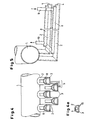
- a strand evaporator is shown in cross section.
- Product flows through the Product entry 11 to the product distributor 17 from manifold 1 and the branching from it Nozzle tubes 2 (see Fig. 6).
- the product stream exits the openings 15 of the nozzle tubes 2 (see Figures 1 and 1a), free falling strands 5 and collects at the bottom of the degassing tank 6.
- a pump 16 promotes the Degassed product in the direction of product discharge 13.
- At the upper lid of the degassing tank 6 are attached to volatile outlet 12.
- Of the Jacket of the degassing tank is designed as a heating jacket 14.
- the nozzle tubes are arranged in a plane next to each other (see FIG. 6 and 7).
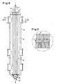
- the product distributor of the strand evaporator is shown schematically in FIG. 1, wherein the product flow through a manifold 1 of a plurality of individual in the Distributor tube 1 opening nozzle tubes 2 is supplied, which in the illustrated and In this respect preferred embodiment are designed as half-tubes 2, and are closed down from perforated plates 3. It is easy to see that in that the individual nozzle tubes 2 directly on the distributor tube 1 of the product entry are mounted in the manifold 1 no Artstotsammlung arise can. In contrast to the embodiment according to FIG. 7, the nozzle tubes 2 according to Fig. 1 in two superposed planes offset from each other.
- the nozzle tubes 2 preferably have a slight inclination to the horizontal in the direction their ends on and beyond that are at their ends with a stopper 4th provided (see Fig. 2a).
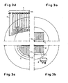
- Fig. 3c In an internal distributor with the solution by means of offset Half pipes 2 have the same number of holes on half the diameter accommodate. This means that the occupancy (number of holes per unit area) four times as large as in the above arrangement. In a triangle arrangement the holes can be almost the densest possible occupancy. With a hole pitch of 4 mm results in a minimum diameter of 1130 mm.
- a curved manifold is shown, which varies long nozzle tubes 2 in the bore area and thus different Throughputs per pipe conditionally, a straight distribution pipe 1 is shown in Fig. 3b, which leads to the same tube lengths and the same throughput per tube 2.
- the manifold may have a central manifold 1, from branch from the nozzle tubes 2 in two directions.
- FIGS. 4 and 5 show that heating of the manifold also takes place is possible.
- a heating tube 8 is on the individual half tubes 2 applied, whose diameter is slightly smaller than that of the half-tube 2 to to avoid an impairment.
- a heating medium is in the direction of the arrow fed at inlet 9 the individual heating tubes and along the arrow at outlet 10 subtracted, so that there is a counter-current heating.
- FIG. 5 It can be seen that the heating of the individual half-tubes 2 by means of individual Although heating pipes 8 means a significant design effort, through the Possibility of gentle product treatment and significant improvement of Product quality, however, this effort is justified.
- the strand evaporator according to the invention leads due to the special structure of the Pipe distributor to a high occupancy and an extremely high flexibility in terms of product throughput and material selection. Further advantages arise through the manufacturing effort and material availability, as the individual Pipes can be easily prefabricated. Also, as already stated, the Brüden entry optimally done, since the volatile constituents with the inventive Arrangement of the individual tubes without design effort above the product outlet can be deducted.
- a styrene-containing SAN copolymer with a content of about 2000 ppm of volatile compounds styrene, acrylonitrile, ethylbenzene (solvent)
- styrene, acrylonitrile, ethylbenzene (solvent) is evaporated.
- a product temperature of 220 ° C results in a viscosity of over 1000 Pa.s.
- a pipe distributor according to FIG. 6 or 7 with half-tubes lying in a plane (similar to FIG. 1 a) is used.
- the downwardly closing half-pipe plate 3 has a wall thickness of 25 mm.
- the holes 15 are made stepped, they taper from 3 to 2 mm.
- the average roughness R a is 3.0 ⁇ m, in the region of the bore diameter of 2 mm (for emergence) the average roughness R a is 1.6 ⁇ m.
- the bore ends are deburred and have a countersink. At a throughput of about 100 g per hour and bore results in a strand evaporator with 6 m long polymer threads, a residual content of volatile compounds of 100 ppm in the degassed product.
Landscapes
- Chemical & Material Sciences (AREA)
- Chemical Kinetics & Catalysis (AREA)
- Engineering & Computer Science (AREA)
- Mechanical Engineering (AREA)
- Dispersion Chemistry (AREA)
- Health & Medical Sciences (AREA)
- Medicinal Chemistry (AREA)
- Polymers & Plastics (AREA)
- Organic Chemistry (AREA)
- Vaporization, Distillation, Condensation, Sublimation, And Cold Traps (AREA)
- Processing And Handling Of Plastics And Other Materials For Molding In General (AREA)
- Details Of Indoor Wiring (AREA)
Applications Claiming Priority (3)
| Application Number | Priority Date | Filing Date | Title |
|---|---|---|---|
| DE19957458 | 1999-11-29 | ||
| DE19957458A DE19957458A1 (de) | 1999-11-29 | 1999-11-29 | Strangverdampfer |
| PCT/EP2000/011468 WO2001039856A1 (de) | 1999-11-29 | 2000-11-17 | Strangverdampfer |
Publications (2)
| Publication Number | Publication Date |
|---|---|
| EP1242156A1 EP1242156A1 (de) | 2002-09-25 |
| EP1242156B1 true EP1242156B1 (de) | 2005-11-16 |
Family
ID=7930764
Family Applications (1)
| Application Number | Title | Priority Date | Filing Date |
|---|---|---|---|
| EP00976044A Expired - Lifetime EP1242156B1 (de) | 1999-11-29 | 2000-11-17 | Strangverdampfer |
Country Status (12)
| Country | Link |
|---|---|
| US (1) | US6780281B1 (enExample) |
| EP (1) | EP1242156B1 (enExample) |
| JP (1) | JP2004502564A (enExample) |
| KR (1) | KR100677792B1 (enExample) |
| CN (1) | CN1224440C (enExample) |
| AU (1) | AU1395101A (enExample) |
| BR (1) | BR0015935A (enExample) |
| DE (2) | DE19957458A1 (enExample) |
| ES (1) | ES2248145T3 (enExample) |
| MX (1) | MXPA02005297A (enExample) |
| TW (1) | TW523422B (enExample) |
| WO (1) | WO2001039856A1 (enExample) |
Families Citing this family (13)
| Publication number | Priority date | Publication date | Assignee | Title |
|---|---|---|---|---|
| DE10036958A1 (de) * | 2000-07-28 | 2002-02-07 | Basf Ag | Verfahren zur Herstellung von tert.-C4-C8-Alkylestern der (Meth)acrylsäure |
| US7682484B2 (en) | 2001-12-20 | 2010-03-23 | Process Development Services, Inc. | Apparatus and method for removing volatile components from viscous liquids |
| DE10330636A1 (de) | 2003-07-07 | 2005-02-10 | Bayer Technology Services Gmbh | Verfahren zur Laugung von Aluminium-Metall-Legierungen |
| DE10333577A1 (de) * | 2003-07-24 | 2005-02-24 | Bayer Technology Services Gmbh | Verfahren und Vorrichtung zur Entfernung von flüchtigen Substanzen aus hochviskosen Medien |
| RU2248834C1 (ru) * | 2003-10-29 | 2005-03-27 | Пензин Роман Андреевич | Установка для очистки углеводородной жидкой среды от растворенных газов |
| DE10359795A1 (de) * | 2003-12-19 | 2005-07-21 | Bayer Technology Services Gmbh | Strangverdampfervorrichtung |
| US7658817B2 (en) | 2004-12-15 | 2010-02-09 | Asahi Kasei Chemicals Corporation | Industrial evaporation apparatus |
| EA010067B1 (ru) * | 2004-12-20 | 2008-06-30 | Асахи Касеи Кемикалз Корпорейшн | Промышленный выпарной аппарат |
| US8241459B2 (en) * | 2006-09-21 | 2012-08-14 | Fina Technology, Inc. | Polymer melt distributor header design |
| DE102008053799A1 (de) | 2008-10-29 | 2010-05-06 | Bayer Materialscience Ag | Extrusionsdüse für Polymere |
| US10058794B2 (en) * | 2016-03-30 | 2018-08-28 | Fina Technology, Inc. | Nozzle/header design for polystyrene |
| EP3728399B1 (de) | 2017-12-18 | 2021-08-18 | Covestro Intellectual Property GmbH & Co. KG | Verfahren zur herstellung eines polycarbonats unter verwendung eines organischen lösungsmittels auf der grundlage von chlorkohlenwasserstoffen |
| WO2023001854A1 (en) | 2021-07-19 | 2023-01-26 | Totalenergies Onetech Belgium | Polymer devolatilization process |
Family Cites Families (9)
| Publication number | Priority date | Publication date | Assignee | Title |
|---|---|---|---|---|
| DE2212816C3 (de) * | 1972-03-16 | 1974-12-12 | Wiegand Karlsruhe Gmbh, 7505 Ettlingen | Vorrichtung zur gleichmäßigen Verteilung einzudampfender Flüssigkeit in einem Fallstromverdampfer |
| US4294652A (en) * | 1980-06-30 | 1981-10-13 | Monsanto Company | Falling strand devolatilizer |
| GB8305015D0 (en) | 1983-02-23 | 1983-03-30 | Shell Int Research | Apparatus for fractional distillation under vacuum |
| US5024728A (en) | 1988-08-29 | 1991-06-18 | Dainippon Ink And Chemicals, Inc. | Devolatilization of liquid composition containing polymer and volatile constituents |
| US4934433A (en) | 1988-11-15 | 1990-06-19 | Polysar Financial Services S.A. | Devolatilization |
| NL9201854A (nl) * | 1992-10-26 | 1994-05-16 | Franciscus Petrus Maria Nooren | Werkwijze en inrichting voor het zuiveren van vloeibaar materiaal, in het bijzonder polysiloxaan alsmede toepassing van het gezuiverde vloeibare materiaal. |
| FI97694C (fi) * | 1994-09-27 | 1997-02-10 | Hadwaco Ltd Oy | Haihduttimen nesteenjakaja |
| DE69813711T2 (de) * | 1997-09-30 | 2004-02-26 | Mitsui Chemicals, Inc. | Verfahren zur Entfernung flüchtiger Stoffe aus einer Polymerzusammensetzung |
| FR2771017B1 (fr) * | 1997-11-17 | 2000-02-04 | Air Liquide | Distributeur de liquide pour colonne de distillation non verticale, et colonne de distillation ainsi equipee |
-
1999
- 1999-11-29 DE DE19957458A patent/DE19957458A1/de not_active Withdrawn
-
2000
- 2000-11-17 DE DE50011659T patent/DE50011659D1/de not_active Expired - Lifetime
- 2000-11-17 CN CNB008164118A patent/CN1224440C/zh not_active Expired - Fee Related
- 2000-11-17 US US10/130,757 patent/US6780281B1/en not_active Expired - Fee Related
- 2000-11-17 EP EP00976044A patent/EP1242156B1/de not_active Expired - Lifetime
- 2000-11-17 BR BR0015935-2A patent/BR0015935A/pt not_active Application Discontinuation
- 2000-11-17 AU AU13951/01A patent/AU1395101A/en not_active Abandoned
- 2000-11-17 KR KR1020027006793A patent/KR100677792B1/ko not_active Expired - Fee Related
- 2000-11-17 WO PCT/EP2000/011468 patent/WO2001039856A1/de not_active Ceased
- 2000-11-17 JP JP2001541583A patent/JP2004502564A/ja not_active Withdrawn
- 2000-11-17 ES ES00976044T patent/ES2248145T3/es not_active Expired - Lifetime
- 2000-11-17 MX MXPA02005297A patent/MXPA02005297A/es unknown
- 2000-11-28 TW TW089125166A patent/TW523422B/zh not_active IP Right Cessation
Also Published As
| Publication number | Publication date |
|---|---|
| DE50011659D1 (de) | 2005-12-22 |
| CN1402648A (zh) | 2003-03-12 |
| MXPA02005297A (es) | 2002-12-13 |
| JP2004502564A (ja) | 2004-01-29 |
| AU1395101A (en) | 2001-06-12 |
| KR20020050794A (ko) | 2002-06-27 |
| TW523422B (en) | 2003-03-11 |
| US6780281B1 (en) | 2004-08-24 |
| EP1242156A1 (de) | 2002-09-25 |
| BR0015935A (pt) | 2002-08-27 |
| DE19957458A1 (de) | 2001-05-31 |
| HK1053994A1 (en) | 2003-11-14 |
| CN1224440C (zh) | 2005-10-26 |
| ES2248145T3 (es) | 2006-03-16 |
| KR100677792B1 (ko) | 2007-02-05 |
| WO2001039856A1 (de) | 2001-06-07 |
Similar Documents
| Publication | Publication Date | Title |
|---|---|---|
| EP1242156B1 (de) | Strangverdampfer | |
| DE68912014T2 (de) | Verfahren zur Entgasung von Polymerlösungen. | |
| EP1656396B1 (de) | Verfahren und vorrichtung zur entfernung von flüchtigen substanzen aus hochviskosen medien | |
| DE3687892T2 (de) | Verfahren und Vorrichtung zum Entgasen von polymerischen Lösungen. | |
| DE10359795A1 (de) | Strangverdampfervorrichtung | |
| DE69106496T2 (de) | Wirbelbettgasverteilerplatte zur Anwendung in einem Gasphasenpolymerisationsapparat. | |
| EP0719582A2 (de) | Reaktorvorrichtung für fliessfähige und höherviskose Medien | |
| EP1347868B1 (de) | Vorrichtung zur durchführung von stoffaustauschprozessen | |
| AT502597A1 (de) | Vorrichtung zum extrudieren von nahrungsteig | |
| EP1077753A1 (de) | Vorrichtung und verfahren zur entfernung von flüchtigen komponenten aus polymerlösungen | |
| DE2842868A1 (de) | Abstrippsaeule sowie abstrippverfahren unter verwendung dieser saeule | |
| DE4447422A1 (de) | Reaktorvorrichtung für fließfähige Medien | |
| DE2555079A1 (de) | Verfahren und vorrichtung zum definierten und schonenden temperieren von hochviskosen loesungen oder schmelzen thermoplastischer kunststoffe | |
| EP2163300B1 (de) | Verwendung einer verteilerplatte zum aufteilen von fluidströmen | |
| EP2083957B1 (de) | Stranggiesskokille | |
| EP3822569A1 (de) | Wärmetauscher | |
| DE102007006811A1 (de) | Vorrichtung zum Filtrieren einer thermoplastischen Kunststoffschmelze | |
| EP0111941B1 (de) | Boden für Destillier- und/oder Absorptionskolonnen | |
| DE19758142A1 (de) | Einrichtung zur Zuführung von Metallschmelze | |
| EP1715196B1 (de) | Kunststoffplatte zum Auskleiden von Betonbauteilen | |
| EP1390116A2 (de) | Verfahren und vorrichtung zur stofftrennung | |
| DE10253225B4 (de) | Schnecke für Ein-Schnecken-Extruder | |
| EP1951392B1 (de) | Rohrbündelwärmeübertrager und verfahren zur entfernung von gelösten stoffen aus einer polymerlösung | |
| DE19533621A1 (de) | Latentwärmespeicher | |
| DE202023003053U1 (de) | Diskontinuierlich betriebener Desublimator mit zumindest einem Strömungsstörer |
Legal Events
| Date | Code | Title | Description |
|---|---|---|---|
| PUAI | Public reference made under article 153(3) epc to a published international application that has entered the european phase |
Free format text: ORIGINAL CODE: 0009012 |
|
| 17P | Request for examination filed |
Effective date: 20020701 |
|
| AK | Designated contracting states |
Kind code of ref document: A1 Designated state(s): AT BE CH CY DE DK ES FI FR GB GR IE IT LI LU MC NL PT SE |
|
| AX | Request for extension of the european patent |
Free format text: AL;LT;LV;MK;RO;SI |
|
| 17Q | First examination report despatched |
Effective date: 20031202 |
|
| RAP1 | Party data changed (applicant data changed or rights of an application transferred) |
Owner name: BAYER MATERIALSCIENCE AG |
|
| RBV | Designated contracting states (corrected) |
Designated state(s): BE DE ES IT NL |
|
| GRAP | Despatch of communication of intention to grant a patent |
Free format text: ORIGINAL CODE: EPIDOSNIGR1 |
|
| GRAS | Grant fee paid |
Free format text: ORIGINAL CODE: EPIDOSNIGR3 |
|
| GRAA | (expected) grant |
Free format text: ORIGINAL CODE: 0009210 |
|
| AK | Designated contracting states |
Kind code of ref document: B1 Designated state(s): BE DE ES IT NL |
|
| REF | Corresponds to: |
Ref document number: 50011659 Country of ref document: DE Date of ref document: 20051222 Kind code of ref document: P |
|
| REG | Reference to a national code |
Ref country code: ES Ref legal event code: FG2A Ref document number: 2248145 Country of ref document: ES Kind code of ref document: T3 |
|
| PLBE | No opposition filed within time limit |
Free format text: ORIGINAL CODE: 0009261 |
|
| STAA | Information on the status of an ep patent application or granted ep patent |
Free format text: STATUS: NO OPPOSITION FILED WITHIN TIME LIMIT |
|
| 26N | No opposition filed |
Effective date: 20060817 |
|
| PGFP | Annual fee paid to national office [announced via postgrant information from national office to epo] |
Ref country code: ES Payment date: 20091201 Year of fee payment: 10 Ref country code: DE Payment date: 20091103 Year of fee payment: 10 |
|
| PGFP | Annual fee paid to national office [announced via postgrant information from national office to epo] |
Ref country code: NL Payment date: 20091104 Year of fee payment: 10 |
|
| PGFP | Annual fee paid to national office [announced via postgrant information from national office to epo] |
Ref country code: IT Payment date: 20091116 Year of fee payment: 10 |
|
| PGFP | Annual fee paid to national office [announced via postgrant information from national office to epo] |
Ref country code: BE Payment date: 20091130 Year of fee payment: 10 |
|
| BERE | Be: lapsed |
Owner name: *BAYER MATERIALSCIENCE A.G. Effective date: 20101130 |
|
| REG | Reference to a national code |
Ref country code: NL Ref legal event code: V1 Effective date: 20110601 |
|
| PG25 | Lapsed in a contracting state [announced via postgrant information from national office to epo] |
Ref country code: BE Free format text: LAPSE BECAUSE OF NON-PAYMENT OF DUE FEES Effective date: 20101130 Ref country code: NL Free format text: LAPSE BECAUSE OF NON-PAYMENT OF DUE FEES Effective date: 20110601 |
|
| REG | Reference to a national code |
Ref country code: DE Ref legal event code: R119 Ref document number: 50011659 Country of ref document: DE Effective date: 20110601 Ref country code: DE Ref legal event code: R119 Ref document number: 50011659 Country of ref document: DE Effective date: 20110531 |
|
| PG25 | Lapsed in a contracting state [announced via postgrant information from national office to epo] |
Ref country code: IT Free format text: LAPSE BECAUSE OF NON-PAYMENT OF DUE FEES Effective date: 20101117 |
|
| REG | Reference to a national code |
Ref country code: ES Ref legal event code: FD2A Effective date: 20120305 |
|
| PG25 | Lapsed in a contracting state [announced via postgrant information from national office to epo] |
Ref country code: ES Free format text: LAPSE BECAUSE OF NON-PAYMENT OF DUE FEES Effective date: 20101118 |
|
| PG25 | Lapsed in a contracting state [announced via postgrant information from national office to epo] |
Ref country code: DE Free format text: LAPSE BECAUSE OF NON-PAYMENT OF DUE FEES Effective date: 20110531 |