EP1241431A1 - Lenkstruktur für Flugkörper - Google Patents
Lenkstruktur für Flugkörper Download PDFInfo
- Publication number
- EP1241431A1 EP1241431A1 EP02005151A EP02005151A EP1241431A1 EP 1241431 A1 EP1241431 A1 EP 1241431A1 EP 02005151 A EP02005151 A EP 02005151A EP 02005151 A EP02005151 A EP 02005151A EP 1241431 A1 EP1241431 A1 EP 1241431A1
- Authority
- EP
- European Patent Office
- Prior art keywords
- missile
- target
- model
- vector
- image
- Prior art date
- Legal status (The legal status is an assumption and is not a legal conclusion. Google has not performed a legal analysis and makes no representation as to the accuracy of the status listed.)
- Withdrawn
Links
Images



Classifications
-
- F—MECHANICAL ENGINEERING; LIGHTING; HEATING; WEAPONS; BLASTING
- F41—WEAPONS
- F41G—WEAPON SIGHTS; AIMING
- F41G7/00—Direction control systems for self-propelled missiles
- F41G7/20—Direction control systems for self-propelled missiles based on continuous observation of target position
- F41G7/22—Homing guidance systems
-
- F—MECHANICAL ENGINEERING; LIGHTING; HEATING; WEAPONS; BLASTING
- F41—WEAPONS
- F41G—WEAPON SIGHTS; AIMING
- F41G7/00—Direction control systems for self-propelled missiles
- F41G7/20—Direction control systems for self-propelled missiles based on continuous observation of target position
- F41G7/22—Homing guidance systems
- F41G7/2226—Homing guidance systems comparing the observed data with stored target data, e.g. target configuration data
-
- F—MECHANICAL ENGINEERING; LIGHTING; HEATING; WEAPONS; BLASTING
- F41—WEAPONS
- F41G—WEAPON SIGHTS; AIMING
- F41G7/00—Direction control systems for self-propelled missiles
- F41G7/20—Direction control systems for self-propelled missiles based on continuous observation of target position
- F41G7/22—Homing guidance systems
- F41G7/2253—Passive homing systems, i.e. comprising a receiver and do not requiring an active illumination of the target
-
- F—MECHANICAL ENGINEERING; LIGHTING; HEATING; WEAPONS; BLASTING
- F41—WEAPONS
- F41G—WEAPON SIGHTS; AIMING
- F41G7/00—Direction control systems for self-propelled missiles
- F41G7/20—Direction control systems for self-propelled missiles based on continuous observation of target position
- F41G7/22—Homing guidance systems
- F41G7/2273—Homing guidance systems characterised by the type of waves
- F41G7/2293—Homing guidance systems characterised by the type of waves using electromagnetic waves other than radio waves
-
- G—PHYSICS
- G01—MEASURING; TESTING
- G01S—RADIO DIRECTION-FINDING; RADIO NAVIGATION; DETERMINING DISTANCE OR VELOCITY BY USE OF RADIO WAVES; LOCATING OR PRESENCE-DETECTING BY USE OF THE REFLECTION OR RERADIATION OF RADIO WAVES; ANALOGOUS ARRANGEMENTS USING OTHER WAVES
- G01S13/00—Systems using the reflection or reradiation of radio waves, e.g. radar systems; Analogous systems using reflection or reradiation of waves whose nature or wavelength is irrelevant or unspecified
- G01S13/66—Radar-tracking systems; Analogous systems
- G01S13/72—Radar-tracking systems; Analogous systems for two-dimensional [2D] tracking, e.g. combination of angle and range tracking, track-while-scan radar
- G01S13/723—Radar-tracking systems; Analogous systems for two-dimensional [2D] tracking, e.g. combination of angle and range tracking, track-while-scan radar by using numerical data
Definitions
- European patent application 1 174 675A1 (not published) relates to one Guiding structure for guiding a missile provided with a sensor system a target, with a measurement vector of observable quantities from the sensor system can be derived.
- a missile should aim for a target, e.g. an enemy aircraft to be destroyed be performed.
- the missile has a seeker head with or several sensors.
- the sensors detect a target. From the signals of this Sensors are derived from steering signals which guide the missile to the target.
- Known missiles have e.g. an image-resolving infrared detector, which consists of a two-dimensional arrangement of detector elements. Through a imaging optical system becomes an object scene containing the target on the Infrared detector shown. The infrared detector thus observes a thermal image, in which e.g. the hot engines of an airplane and their exhaust gas jet as intense Radiation source appear. Through image processing, the Infrared detector delivered "electronic image" the position of the target in the visual field determined.
- the seeker head is stabilized in space and by the Missile movements decoupled.
- the search head can also with the Infrared detector rigidly sitting in the missile, being also rigid with the cell of the Missile connected (“strap-down") inertial sensors the decoupling of the electronic image of the movement of the missile.
- the search head is usually tracked real or virtual to the target. From this The line rotation rate is determined by tracking. The steering takes place at the "Proportional navigation" so that the lateral acceleration of the missile is proportional this line of sight rotation rate is.
- the goal e.g. an attacked aircraft usually also has sensors which recognize the attack by an approaching missile.
- the target hits "Countermeasures" that seek to disrupt the approaching missile or distract.
- the attacked aircraft is made by suitable maneuvers seek to escape the approaching missile.
- the movement of the Missile itself determined and considered by an inertial measuring unit.
- the Movement quantities of the target are unknown.
- the expected behavior of the Target such as whether the target performs an escape maneuver and how this escape maneuver the missile does not "know”.
- the missile only detects the line of sight to the Target, if necessary distance and change of distance and reacts to their changes.
- the invention of the main patent is based on the task Hit probability when using a missile against highly agile targets improve and especially for the guidance of the missile "Encounter kinematics", ie using the movements of the missile and target.
- this object is achieved in that a in the missile Model of missile-target relative kinematics and sensor system is shown that Model can be modified by means of optimal filtering, which depends on the deviation of a the measurement vector resulting from the model is acted upon by the real measurement vector are, with the modification an adaptation of the model to reality is targeted, and the missile depending on one in the model generated, representing the relative kinematics of missile and target Relative kinematics vector is steerable.
- a model is created in a missile-side computer of both the missile and the sensor system as well as the target.
- the Sensor system delivers a real measurement vector.
- the measurement vector results from the real one Relative kinematics of missile and target.
- the real measurement vector is shown with a estimated measurement vector, which is derived from the model of missile, target and Sensor system results.
- the real and the estimated measurement vector are usually do not match, especially since the movement states of the target are not known are. Therefore an optimal filter, e.g.
- the main patent continues to suggest estimating means for estimating the target acceleration to which the measurement vector, image data from an image-resolving detector of the missile and data from the inertial measurement unit of the Missile are activated and by which the model can be corrected.
- the main patent also suggests that the estimating means be appropriately trained neural network or a fuzzy neural network.
- the measurement vector z is thus once applied to the neural or fuzzy-neuronal network.
- the or fuzzy-neural network receives image data from an image sensor or image-resolving detector.
- the neural or fuzzy-neural network is trained in such a way that it delivers estimated values for the lateral acceleration of the target from these input variables.
- the neural or fuzzy-neural network exploits, for example, the fact that a lateral acceleration of an aircraft forming the target is accompanied by a change in position of the aircraft in space and thus a characteristic change in the contour, which is "seen" from the missile.
- the extent and direction of the lateral acceleration can be inferred from such a contour change.
- the optimal filter requires less computing effort to adapt the model of the missile and target to reality.
- the present additional invention relates to a preferred embodiment of the Estimating means for estimating the target acceleration.
- Accelerating an aircraft forming the target first requires a change in the position of the aircraft in space: to climb or descend, i.e. vertical acceleration, the aircraft must change the angle of attack, i.e. the position of its longitudinal axis in space.
- a lateral acceleration of the aircraft requires an inclined position and thus a change in the aspect angle from which the aircraft is viewed.
- the image information that is supplied directly by the image-resolution detector contains a very large, confusing number of pixels.
- the estimating means initially generate a limited number of feature sizes through image processing. These feature sizes define, for example, the longitudinal axis of the image of an aircraft forming the target and the maximum dimensions of this image along and across this longitudinal axis.
- the very large amount of image information from the pixels of the image-resolution detector is initially reduced to a few essential feature sizes by image processing.
- These feature quantities are then switched to a system capable of learning, such as a neural or fuzzy-neuronal network.
- This learnable system is then trained to generate estimated values for the lateral acceleration a T of the target from the feature quantities.
- the measurement vector of the Sensor system switched on. This provides e.g. Distance information or or Information about the line of sight rotation rate and facilitate the evaluation of the Image information from the image resolution detector.
- a further advantageous embodiment of the invention is that the optimal filter is designed to estimate the relative kinematics vector without taking into account the target acceleration and the difference between the estimated value of the estimated measurement vector ( z and ) from the model modified by the optimal filter and the real measurement vector ( z ) is additionally connected to the system capable of learning and is taken into account when training this system.
- Block 12 designates the flight controller of the target, an enemy aircraft to be attacked.
- the target dynamics 14 provides the change of a state vector x ⁇ T of the target.
- a block 16 represents the autopilot of a missile.
- the autopilot 16 receives a commanded lateral acceleration a MC at an input 18 in a manner to be described.
- the autopilot 16 receives signals from an inertial measurement unit ("IMU").
- IMU inertial measurement unit
- the change x ⁇ M of the state vector of the missile results from the missile dynamics . This change x ⁇ M of the state vector of the missile acts on the inertial measurement unit 22 of the missile.
- the changes in the state vectors x ⁇ T and x ⁇ M of the target and the missile result in a change in the relative kinematics, which is represented by a vector x ⁇ R.
- a vector x ⁇ R This is shown schematically in FIG. 1 by a summing point 24.
- the vector x ⁇ R of the change in the relative kinematics is integrated, which is represented by block 26. This returns the vector x R.
- "s" is the Laplace transform variable.
- the relative kinematics identified by vector x R is detected by sensors which form a sensor system 28. These sensors can be passive sensors such as image-resolving infrared sensors, or active sensors such as radar or laser sensors.
- the sensor system delivers signals according to the line of sight ⁇ , the line of sight rotation rate ⁇ ⁇ , the distance R between the missile and the target and its change R ⁇ . These signals are subjected to signal processing 30 and provide a real measurement vector z .
- the missile now contains a model 31 of the real world described above in a computer.
- this model 31 is outlined in FIG. 1 by a dashed line.
- This model includes a model 32 of the missile and a model 34 of the target.
- the signals of the (real) inertial measurement unit 22 are applied to the model 32 of the missile.
- the model 32 of the missile provides an estimate the change in the state vector of the missile.
- the model 34 of the target provides an estimate the change in the state vector of the target. From the two vectors and a vector results which represents the change in the relative kinematics between the missile and the target as an estimate in the model.
- the vector is integrated as represented by block 38. That gives an estimate of the vector of relative kinematics.
- the sensor model 40 is a model of the sensors and the associated signal processing.
- the sensor model 40 delivers an estimated value z and the measurement vector.
- the estimated value z and the measurement vector will initially not match the real measurement vector.
- This difference is switched to an optimal filter 44.
- This optimal filter 44 can be, for example, a Kalman filter, an extended Kalman filter or a solution to the state-dependent Riccati equation (SDRE).
- SDRE state-dependent Riccati equation
- the parameters of the model are modified by the optimal filter 44 in order to adapt the model 31 to reality. This is shown symbolically in FIG. 1 by the addition of a vector ⁇ from the optimal filter 44 to the summing point 36.
- the vector corrected which leads to a corrected relative kinematics vector x and R after integration.
- the estimated value z and of the measurement vector are matched to the real measurement vector z .
- the relative kinematics vector x and R resulting from the model is now connected to an optimal steering controller 46, which applies a commanded lateral acceleration a MC to the autopilot of the missile.
- the optimal filter is designed so that it does not take the target acceleration a T into account by modifying the model accordingly.
- the steering structure additionally contains a knowledge-based estimation element 50 for estimating the target acceleration.
- the measurement vector z is applied to this estimation element 50 once.
- the estimation element 50 receives image data from an image sensor or image-resolution detector.
- the signals of the inertial measuring unit are also applied to the estimation element 50 and take into account the own movement of the missile. From these input variables, the estimation element 50 supplies estimates for the lateral acceleration of the target.
- the measured data of the measurement vector are, for .
- the measured data of the measurement vector are, for .
- the optimal filter delivers an estimated value z and the measurement vector from the model.
- the difference (residual) is connected to the summing point 64 via an amplifier 62 with the factors K ( x and R , t).
- the state vector x R is defined, for example, by the following elements:
- the function g ( x and R ) is corrected by the residual multiplied by the factors K ( x and R , t). That gives an estimate for the time derivation of the state vector of the relative kinematics of missile and target. Integration, represented by a block 68, gives the estimated value of the state vector of the relative kinematics x and R.
- a function h ( x and R ) of this estimate, represented by block 70, which represents the sensor model, supplies the estimate z and the measurement vector. The difference between the estimated value z and the real measurement vector is formed at a summing point 72. This is the construction of a Kalman filter.
- the target acceleration a T would then also be calculated by the optimal filter, which would require considerable computing effort.
- the optimal filter is now deliberately designed so that the target acceleration a T is not taken into account. This leads to an increase in the residual , The growth of the residual is therefore an indication and measure for the occurrence of a target acceleration a T.
- the estimation element now contains a feature generator 74.
- the feature generator 74 primarily performs image processing of the image data supplied by an image-resolution detector 76. This is indicated by block 78 in Figure 4.
- the feature generator receives the standard measurement data which are summarized in the measurement vector z .
- the feature generator 74 supplies a limited number of features which characterize the observed contour of the target, here an aircraft, from the large number of image data (pixels). These are, for example, the direction of the aircraft longitudinal axis and the maximum dimensions of the image of the aircraft in the direction of the aircraft longitudinal axis and perpendicular to it.
- a change in the position of the aircraft's longitudinal axis in the image indicates a change in the angle of attack of the aircraft, which leads to a lateral acceleration of the aircraft in the vertical direction.
- a change in the maximum dimensions transverse to the longitudinal axis indicates a rolling movement of the aircraft and thus lateral lateral acceleration.
- the features thus obtained are quantitative feature sizes. These feature quantities are applied to an estimator 80 (FIG. 3).
- the estimator 80 is a neural or fuzzy-neuronal network, as represented by block 82 in FIG.
- the residual is also connected to the estimator 80 of the optimal filter 44.
- the neural or fuzzy-neuronal network of the estimator 82 is trained off-line using examples so that it consists of the feature sizes from the feature generator 74 and the residual provides an estimate of the target acceleration â T. As shown in FIG. 1, this estimated value â T is applied to the model of the relative kinematics as a measured variable. The estimated value for the target acceleration a T thus appears here as a measured variable which is essentially obtained from the image processing of the image by the image-resolving detector 76 and need not be calculated by the optimal filter 44. The computing effort of the optimal filter 44 is thus significantly reduced.
Landscapes
- Engineering & Computer Science (AREA)
- Chemical & Material Sciences (AREA)
- Combustion & Propulsion (AREA)
- General Engineering & Computer Science (AREA)
- Physics & Mathematics (AREA)
- Electromagnetism (AREA)
- Aiming, Guidance, Guns With A Light Source, Armor, Camouflage, And Targets (AREA)
Abstract
Description
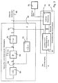
- Fig.1
- ist ein Blockdiagramm einer Lenkstruktur zum Lenken eines mit einem Sensorsystem und einem bildauflösenden Detektor versehenen Flugkörpers zu einem Ziel, wobei die Anpassung des Modells der Begegnungssituation an die reale Welt durch ein Optimalfilter erfolgt, wobei aber zusätzlich eine Schätzung der Zielbeschleunigung und Berücksichtigung des so erhaltenen Schätzwertes erfolgt.
- Fig.2
- veranschaulicht die Relativkinematik von Flugkörper und Ziel.
- Fig.3
- ist ein Blockdiagramm und zeigt das Optimalfilter und die Mittel zum Schätzen der Zielbeschleunigung aus den Bildinformationen eines das Ziel beobachtenden bildauflösenden Detektors.
- Fig.4
- ist ein Blockdiagramm und veranschaulicht in einer anderen Darstellung die Mittel zum Schätzen der Zielbeschleunigung.


Claims (5)
- Lenkstruktur zum Lenken eines mit einem Sensorsystem versehenen Flugkörpers zu einem Ziel, wobei aus dem Sensorsystem ein Meßvektor (z) von beobachtbaren Größen ableitbar ist, bei welcher in dem Flugkörper ein Modell von Flugkörper-Ziel-Relativkinematik und Sensorsystem dargestellt ist, das Modell durch ein Optimalfilter modifizierbar ist, welches von der Abweichung eines sich aus dem Modell ergebenden Meßvektors ( z and ) von dem realen Meßvektor (z) beaufschlagt ist, wobei durch die Modifikation eine Anpassung des Modells an die Realität angestrebt wird, der Flugkörper in Abhängigkeit von einem in dem Modell erzeugten, die relative Kinematik von Flugkörper und Ziel darstellenden Relativkinematik-Vektor ( x and R ) lenkbar ist und Schätzermittel zum Schätzen der Zielbeschleunigung mit einem entsprechend trainierten neuronalen Netz vorgesehen sind, auf welche Bilddaten von einem bildauflösenden Detektor des Flugkörpers aufgeschaltet sind und durch welche das Modell korrigierbar ist, nach Anspruch 4 und 6 des Patentes ... (Patentanmeldung 100 33 368.0), dadurch gekennzeichnet, daß(a) die Schätzermitte (50) Mittel (74) zur Merkmalsgewinnung enthalten, auf welche die Bilddaten von dem bildauflösenden Detektor (76) aufgeschaltet sind und welche durch Bildverarbeitung daraus eine begrenzte Anzahl von Merkmalsgrößen zur Charakterisierung des Zielbildes erzeugen, und(b) die Merkmalsgrößen auf ein lernfähiges System (80) aufgeschaltet sind, das zur Erzeugung eines Schätzwertes für die Zielbeschleunigung (aT) trainiert ist.
- Lenkstruktur nach Anspruch 1, dadurch gekennzeichnet, daß auf die Mittel zur Merkmalsgewinnung zusätzlich der Meßvektor (z) des Sensorsystems (28) aufgeschaltet ist.
- Lenkstruktur nach Anspruch 1 oder 2, dadurch gekennzeichnet, daß das lernfähige System (80) ein neuronales Netz ist.
- Lenkstruktur nach Anspruch 1 oder 2, dadurch gekennzeichnet, daß das lernfähige System (80) ein fuzzy-neuronales Netz ist.
- Lenkstruktur nach einem der Ansprüche 1 bis 4, dadurch gekennzeichnet, daß(a) das Optimalfilter (44) zur Schätzung des Relativkinematik-Vektors ohne Berücksichtigung der Zielbeschleunigung ausgelegt ausgelegt ist und(b) die Differenz des Schätzwertes des geschätzten Meßvektors ( z and ) aus dem durch das Optimalfilter (44) modifizierten Modell und dem realen Meßvektor (z) zusätzlich auf das lernfähige System (80) aufgeschaltet und beim Trainieren dieses Systems (80) berücksichtigt ist.
Applications Claiming Priority (2)
| Application Number | Priority Date | Filing Date | Title |
|---|---|---|---|
| DE10112692 | 2001-03-16 | ||
| DE2001112692 DE10112692A1 (de) | 2001-03-16 | 2001-03-16 | Lenkstruktur für Flugkörper |
Publications (1)
| Publication Number | Publication Date |
|---|---|
| EP1241431A1 true EP1241431A1 (de) | 2002-09-18 |
Family
ID=7677716
Family Applications (1)
| Application Number | Title | Priority Date | Filing Date |
|---|---|---|---|
| EP02005151A Withdrawn EP1241431A1 (de) | 2001-03-16 | 2002-03-07 | Lenkstruktur für Flugkörper |
Country Status (2)
| Country | Link |
|---|---|
| EP (1) | EP1241431A1 (de) |
| DE (1) | DE10112692A1 (de) |
Citations (3)
| Publication number | Priority date | Publication date | Assignee | Title |
|---|---|---|---|---|
| US5253823A (en) * | 1983-10-07 | 1993-10-19 | The Secretary Of State For Defence In Her Britannic Majesty's Government Of The United Kingdom Of Great Britain And Northern Ireland | Guidance processor |
| DE4218600A1 (de) * | 1992-06-05 | 1993-12-09 | Bodenseewerk Geraetetech | Einrichtung zur Bestimmung von Bewegungsgrößen eines Flugkörpers |
| EP1174675A1 (de) | 2000-07-08 | 2002-01-23 | Bodenseewerk Gerätetechnik GmbH | Lenkstruktur für Flugkörper |
-
2001
- 2001-03-16 DE DE2001112692 patent/DE10112692A1/de not_active Withdrawn
-
2002
- 2002-03-07 EP EP02005151A patent/EP1241431A1/de not_active Withdrawn
Patent Citations (3)
| Publication number | Priority date | Publication date | Assignee | Title |
|---|---|---|---|---|
| US5253823A (en) * | 1983-10-07 | 1993-10-19 | The Secretary Of State For Defence In Her Britannic Majesty's Government Of The United Kingdom Of Great Britain And Northern Ireland | Guidance processor |
| DE4218600A1 (de) * | 1992-06-05 | 1993-12-09 | Bodenseewerk Geraetetech | Einrichtung zur Bestimmung von Bewegungsgrößen eines Flugkörpers |
| EP1174675A1 (de) | 2000-07-08 | 2002-01-23 | Bodenseewerk Gerätetechnik GmbH | Lenkstruktur für Flugkörper |
Also Published As
| Publication number | Publication date |
|---|---|
| DE10112692A1 (de) | 2002-09-19 |
Similar Documents
| Publication | Publication Date | Title |
|---|---|---|
| EP1926654B1 (de) | Verfahren und vorrichtung zum lenken eines kraftfahrzeugs | |
| EP1079198B1 (de) | Verfahren zur Bestimmung der Relativbewegung zwischen Flugkörper und Ziel | |
| DE1936820C1 (de) | Zielverfolgungsgerät für Luftfahrzeuge | |
| DE69411398T2 (de) | Integrierte feuer- und flugsteuerung für hubschrauber mit einem leitsystem vor und nach dem abschuss | |
| DE102007018190B3 (de) | Verfahren Anordnung und Track-System zur Ermittlung und Vorhersage einer Bewegung eines Zielobjektes | |
| EP0714013B1 (de) | Lenkschleife für Flugkörper | |
| DE69931216T2 (de) | Flugbahnbefehlssteuerung mit neuronalem netzwerk | |
| DE102016114366B4 (de) | Ausfallsicheres inertiales messeinheitssystem reduzierter ordnung | |
| DE3442598C2 (de) | Leitsystem für Flugkörper | |
| DE19645556A1 (de) | Vorrichtung zur Erzeugung von Lenksignalen für zielverfolgende Flugkörper | |
| DE69128366T2 (de) | Kombiniertes Sensorlenksystem | |
| DE4218600C2 (de) | Einrichtung zur Bestimmung von Bewegungsgrößen eines Flugkörpers | |
| EP1020699B1 (de) | Flugkörper | |
| DE19857895A1 (de) | Lenk-, Navigations- und Regelsystem für Flugkörper | |
| EP3882569B1 (de) | Verfahren zur ermittlung eines zielobjekts, elektro-optisches sensorsystem, verfahren zur navigation eines lenkflugkörpers und lenkflugkörper | |
| DE19601846A1 (de) | Verfahren zum Lenken und Einstellen der Fluglage von Raketen | |
| DE69730278T2 (de) | Passive Entfernungsabschätzung unter Verwendung von Bildgrösseabmessungen | |
| EP1241431A1 (de) | Lenkstruktur für Flugkörper | |
| DE10033368A1 (de) | Lenkstruktur für Flugkörper | |
| EP0974806A1 (de) | Verfahren zum Trainieren eines neuronalen Netzes für die Lenkung eines Flugkörpers zu einem Ziel | |
| DE69213615T2 (de) | Verfahren und Anordnung für ein Waffensystem | |
| DE4223531C2 (de) | Einrichtung zur Führung eines aus einem Werfer abgeschossenen, angetriebenen Flugkörpers | |
| EP0727638A1 (de) | Verfahren und Vorrichtung zur Bekämpfung verdeckt operierender Hubschrauber | |
| EP0733546B1 (de) | Verfahren zur Sonnensuche für einen dreiachsenstabilisierten Satelliten und dreiachsenstabilisierter Satellit | |
| DE19543048A1 (de) | Vorrichtung zur Erzeugung von Lenksignalen für zielverfolgenden Flugkörper |
Legal Events
| Date | Code | Title | Description |
|---|---|---|---|
| PUAI | Public reference made under article 153(3) epc to a published international application that has entered the european phase |
Free format text: ORIGINAL CODE: 0009012 |
|
| AK | Designated contracting states |
Kind code of ref document: A1 Designated state(s): AT BE CH CY DE DK ES FI FR GB GR IE IT LI LU MC NL PT SE TR |
|
| AX | Request for extension of the european patent |
Free format text: AL;LT;LV;MK;RO;SI |
|
| 17P | Request for examination filed |
Effective date: 20020831 |
|
| AKX | Designation fees paid |
Designated state(s): AT BE CH CY DE DK ES FI FR GB GR IE IT LI LU MC NL PT SE TR |
|
| 17Q | First examination report despatched |
Effective date: 20040513 |
|
| RAP1 | Party data changed (applicant data changed or rights of an application transferred) |
Owner name: DIEHL BGT DEFENCE GMBH & CO.KG |
|
| RTI1 | Title (correction) |
Free format text: GUIDANCE SYSTEM FOR MISSILE |
|
| GRAP | Despatch of communication of intention to grant a patent |
Free format text: ORIGINAL CODE: EPIDOSNIGR1 |
|
| STAA | Information on the status of an ep patent application or granted ep patent |
Free format text: STATUS: THE APPLICATION IS DEEMED TO BE WITHDRAWN |
|
| 18D | Application deemed to be withdrawn |
Effective date: 20060503 |