EP1239263B1 - Positionsmessvorrichtung und Bearbeitungsapparat mit dieser Vorrichtung - Google Patents
Positionsmessvorrichtung und Bearbeitungsapparat mit dieser Vorrichtung Download PDFInfo
- Publication number
- EP1239263B1 EP1239263B1 EP02251471.5A EP02251471A EP1239263B1 EP 1239263 B1 EP1239263 B1 EP 1239263B1 EP 02251471 A EP02251471 A EP 02251471A EP 1239263 B1 EP1239263 B1 EP 1239263B1
- Authority
- EP
- European Patent Office
- Prior art keywords
- moving machine
- direction moving
- coordinate
- error
- detector
- Prior art date
- Legal status (The legal status is an assumption and is not a legal conclusion. Google has not performed a legal analysis and makes no representation as to the accuracy of the status listed.)
- Expired - Lifetime
Links
Images


Classifications
-
- G—PHYSICS
- G01—MEASURING; TESTING
- G01B—MEASURING LENGTH, THICKNESS OR SIMILAR LINEAR DIMENSIONS; MEASURING ANGLES; MEASURING AREAS; MEASURING IRREGULARITIES OF SURFACES OR CONTOURS
- G01B21/00—Measuring arrangements or details thereof, where the measuring technique is not covered by the other groups of this subclass, unspecified or not relevant
- G01B21/02—Measuring arrangements or details thereof, where the measuring technique is not covered by the other groups of this subclass, unspecified or not relevant for measuring length, width, or thickness
- G01B21/04—Measuring arrangements or details thereof, where the measuring technique is not covered by the other groups of this subclass, unspecified or not relevant for measuring length, width, or thickness by measuring coordinates of points
- G01B21/045—Correction of measurements
Definitions
- the present invention relates to an improvement of a compensation mechanism for compensating an error of a measured coordinate position, in a moving machine having a coordinate space mechanism such as a Coordinate Measuring Machine, a machine tool, a robot and the like.
- a position measuring apparatus which can execute a position measurement within a three-dimensional space has been used for executing an accurate operation, in various moving machines such as the Coordinate Measuring Machine, the machine tool, the robot and the like.
- the Coordinate Measuring Machine it is possible to determine a distance from a first target position to a second target position in a subject to be measured by measuring coordinates of the first target position and the second target position. If the manner mentioned above is continuously used, it is possible to accurately comprehend a two-dimensional or three-dimensional shape of the measured subject.
- a key point in volumetric measuring accuracy correction of the Coordinate Measuring Machine is the geometrical error. Accordingly, a basic operation order of the software is shown by a block diagram in Fig. 5 . As shown in Fig. 5 , the software of this kind at first mounts a length reference device such as a gauge block or a step gauge, or an angle reference device such as a right angle reference device on a table of the Coordinate Measuring Machine. Then, a measurement is executed by setting these reference devices as a workpiece. Next, the geometrical error data are determined on the basis of these measured values, a command value of a position at a time of executing the measurement, the error of the reference devices themselves and the like.
- a length reference device such as a gauge block or a step gauge
- an angle reference device such as a right angle reference device
- ranges with appropriate length are determined by analyzing the error data.
- the errors are approximated in accordance with a function (data fit), thereafter, the errors are classified into respective error kinds at every axis in accordance with a kinematic model of the measuring apparatus, and a compensation parameter with respect to the measured coordinate is prepared. The parameter is stored and the compensation with respect to the measured coordinate is executed.
- the kinematic model is used for the isolation process of the errors.
- the geometrical errors isolated by using the kinematic model has three scale errors in a rectangular coordinates system each one being with respect to the respective axis, three errors in a straightness within a vertical plane each one being with respect to the respective axis, three errors in a straightness within a horizontal plane each one being with respect to the respective axis, three pitching errors each one being with respect to the respective axis, three yaw errors each one being with respect to the respective axis, three rolling errors each one being with respect to the respective axis, and three perpendicular errors between the respective axis (xy axis, yz axis and zx axis), and totally has twenty one errors.
- This kinematic model is used for isolation the errors at a time of computing the compensation parameter and at the same time, is used at a time of converting the respective compensation parameter into the errors on the coordinate space at a time of executing the compensation.
- a guide for the moving machine provided on the reference surface has a particularly important role. Even when the high accuracy of the Coordinate Measuring Machine is realized by utilizing the space accuracy compensation in accordance with the software, a deterioration of accuracy in the Coordinate Measuring Machine is directly caused if the guide for the moving machine provided on the reference surface is changed due to a deterioration with age or a temperature fluctuation. Therefore, in the conventional art, in the same manner as mentioned above, a countermeasure is given by increasing the static rigidity and controlling the ambient temperature.
- DE19830646 discloses a method of correcting geometrical collection of errors in an axis of coordinate measuring machine by applying a correction factor derived from part of a volume to measurement result in which the method stores a correction value derived for at least part of the volume being measured in control unit, and this value is applied, depending on the result of measurement during measurement of a workpiece.
- EP0687890 discloses a procedure and device to eliminate roll about an axis of a coordinate measuring machine in which the roll angle is eliminated with the aid of the beam from a laser via the Wollaston prism which forms two coherent partial beams directed at surfaces of a translation reflector fixed to the machine.
- the prism is fixed to the axis of the machine by means of a lever at right angles to the axis and movable in the direction of its length between two positions.
- the roll angle is determined from the two measurements with allowance for tilt of the measurement axis.
- EP0275428 a method and system are disclosed for automatically calibrating a coordinate measuring machine (CMM).
- CMS coordinate measuring machine
- the system automatically converts the collected data into error compensation or axis correction data which represents different geometry errors (i.e. pitch, yaw, roll etc.) of the CMM.
- the error compensation data is then transferred to a CMM measurement processor for subsequent use by the CMM during operation thereof to hereby compensate the CMM for its entire measuring volume.
- FR2330997 discloses a machine for measuring the dimensions of a workpiece, comprising a base plate for receiving the workpiece and a mechanical structure carrying a feeler for movement along three orthogonal axes at right angles by means providing for direct measuring of the amounts of movement of the feeler along the axes.
- Optical deviation measurement means determine the errors due to deformation of the components, lost motion as well as pitch, yaw and/or roll of the movable components.
- the corrections to be applied to the data delivered by the measuring means are computed and may be made automatically for the display to be free of errors.
- EP0657715 discloses a method and device for the correction of measurement of errors in which for the correction of measurement errors, due to vibration, of coordinate measuring devices, the time course of the interfering vibrations is stored by means of sensors (a x , a y , a z ) on a vibrating portion of the coordinate measuring device.
- the measured values of the sensors are adjusted with previously determined and stored correction parameters, which describe the natural frequency (v) and the damping constants ( ⁇ ) of the vibrations and also the amplitude and phase information of the characteristic modes (G r ) of the vibrations contributing to the interfering vibrations.
- the measurement errors, due to vibration, of the coordinate measuring device at the instant of probing are then calculated from the time course of the corrected measurement values of the sensors (a x ,a y ,a z ).
- the present invention is made in consideration of the problems mentioned above, and a first object of the present invention is to provide a position measuring apparatus which can execute a stable accuracy assurance at a high accuracy against a deterioration with age and a temperature fluctuation of the apparatus while making a correction of an existing volumetric measuring accuracy effective. Further, a second object of the present invention is to provide an apparatus which can execute a further accuracy stability and improve a reliability while keeping a general-purpose property even in a Coordinate Measuring Machine.
- a position measuring apparatus comprising: a target position detector for detecting a target position in a coordinate space with respect to a predetermined reference surface; a moving machine moving in accordance with a predetermined relation with respect to the reference surface so as to move said target position detector for the purpose of detecting the target position by said target position detector; a positional coordinate computer for computing a positional coordinate of the target position on the basis of a data such as a displacement of said moving machine; a position coordinate measuring mechanism constituted by said target position detector, said moving machine and said positional coordinate computer; a memory classifying geometrical errors on the basis of a positional coordinate measured by said position coordinate measuring mechanism and storing compensation parameters determined from the respective classified errors; an error compensator for reading out the compensation parameters so as to compensate the errors; and target position within a specified coordinate space being measured on the basis of a coordinate system, wherein the position measuring apparatus comprises:
- the target position detector detects the target position in the coordinate space with respect to a predetermined reference surface.
- the moving machine moves in accordance with a predetermined relation with respect to the reference surface for the purpose of detecting the target position by the target position detector so as to move the target position detector.
- the positional coordinate computer computes the target position from the data such as the displacement of the moving machine.
- the coordinate system is an xyz rectangular coordinates system in which the coordinate system is extended in vertical, horizontal and height directions.
- the moving machine comprises:
- the detector is constituted by a reference side angle meter and a measurement side angle meter.
- the moving machine comprises:
- the angle meter is a biaxial angle level.
- the angle meter is a laser angle level.
- the coordinate system is a biaxial rectangular coordinates system.
- an amount of change of the relation measured by the detector includes a pitching error and a yaw error with respect to an axis in a specified linear direction.
- a memory for saving an amount of change of the relation measured by the detector is further provided, and the detector is detachably provided.
- a working apparatus in accordance with the present invention has a feature that the position measuring apparatus in accordance with the present invention is provided.
- Fig. 1 shows a block diagram of a structure summary of an embodiment of a position measuring apparatus in accordance with the present invention.
- a position measuring apparatus 2 in accordance with the present invention shown in Fig. 1 is provided with a positional coordinate measuring mechanism 12 constituted by a target position detector 6, a moving machine 8 and a positional coordinate computer 10. Further, it has a geometrical error measuring instrument 14 and an error compensator 16. Further, it measures a target position within a specified three-dimensional space on the basis of a three-axis coordinate system.
- the target position detector 6 detects a target position in a coordinate space with respect to a predetermined reference surface 4.
- the moving machine 8 moves in accordance with a predetermined relation with respect to the reference surface 4 in order to detect the target position by the target position detector 6, thereby moving the target position detector 6.
- the positional coordinate computer 10 computes a positional coordinate of the target position on the basis of the data such as the displacement(amount of displacement) of the moving machine 8.
- the geometrical error measuring instrument 14 measures and computes the geometrical error on the basis of the positional coordinate measured by the positional coordinate measuring mechanism 12. The error is classified and a compensation parameter is computed with respect to each of the classified errors.
- the error compensator 16 compensates the error by using the compensation parameter computed by the geometrical error measuring instrument 14.
- a characteristic matter in the position measuring apparatus in accordance with the present invention is a matter that there are provided a relational change measuring mechanism (detector) 18 detachably provided with respect to the positional coordinate measuring mechanism 12, and an error corrector 20.
- the relational change measuring mechanism 18 measures whether or not a change is occurred in a relation to the reference surface 4, in the motion which the moving machine 8 executes.
- the error corrector 20 further corrects the positional coordinate compensated by the error compensator 16 in order to remove the influence given to the positional coordinate computed by the positional coordinate computer 10 due to the change of the relation with respect to the reference surface 4 and the motion executed by the moving machine 8, on the basis of the displacement of the relation measured by the relational change measuring mechanism 18, in the case that any change is occurred.
- the correction parameter is stored by a memory(not shown), is read out by the error compensator 16, and is used for compensating the error.
- error compensation data computed by the error corrector 20 is stored by a memory (not shown), is read out by the error corrector 20 and is used for executing an accurate volumetric measuring accuracy correction by further applying an error correction to the positional coordinate compensated the error.
- FIG. 2 shows a block diagram of a structure summary of a second embodiment in accordance with the present invention.
- the same reference numerals are attached to the same components as those in Fig. 1 , and a description thereof will be omitted.
- the position measuring apparatus 2 shown in Fig. 2 is structured such that when a specified positional coordinate is computed by the positional coordinate measuring mechanism 12, the compensation parameter computed by the geometrical error measuring instrument 14 in the positional coordinate is read out. At a time of compensating the positional coordinate by the error compensator 16 from the information, the compensation parameter compensating the positional coordinate of the error compensator 16 is corrected by the error corrector 20.
- the apparatus is structured such that an accurate positional coordinate is computed. Even in the embodiment mentioned above, the same effects can be obtained.
- Fig. 3 is a schematic view of a structure of a position measuring apparatus corresponding to an embodiment in accordance with the present invention.
- the same reference numerals are attached to the same components as those in Fig. 1 , and a description will be omitted.
- a position measuring apparatus corresponding to one embodiment in accordance with the present invention is provided with a base 4 corresponding to the reference surface. Further, it is provided with a controller 22 and a data processor 24.
- the controller 22 controls the apparatus such as the moving machine 8 and the like.
- the data processor 24 executes various data processes such as the position measured data and an analysis thereof.
- the positional coordinate computer 10 is constituted by the controller 22 and the data processor 24.
- the data such as displacement of the target position detector 6 moved by the moving machine 8 is received by the controller 22 through an interface 26 provided in the controller 22.
- the data received by the controller 22 is transmitted to the data processor 24 and is analyzed. Further, the positional coordinate is computed by the data processor 24.
- the geometrical error measuring instrument 14 measures the data such as a motion property of the position measuring apparatus 2 previously measured by a measurement standard or the like, and a deformation together with the motion.
- the data is stored in a correction parameter memory such as a hard disc provided in the data processor 24, as the compensation parameter.
- the error compensator 16 is a software for applying a volumetric measuring accuracy correction to the positional coordinate measured by the positional coordinate measuring mechanism 12 by using the geometrical error information of the geometrical error measuring instrument 14.
- This software is stored in the hard disc of the data processor or the like in the same manner as the geometrical error measuring instrument 14. This software is automatically executed on the basis of a user desire or an operating program of the apparatus.
- the error corrector 20 is a software for further correcting the error included in the positional coordinate compensated by the error compensator 16 due to a reason that the relation between the motion of the moving machine 8 and the reference surface (the base 4) is changed, on the basis of the measurement result of the relational change measuring mechanism 18. Further, the error corrector 20 and the error correction data computed by the error corrector 20 are stored in the hard disc of the data processor or the like in the same manner as that of the geometrical error measuring instrument 14 and the error compensator 16.
- the geometrical error property in the positional coordinate is read out from the memory.
- the positional coordinate compensated the error by the error compensator 16 is calculated from the read-out information.
- the error due to the influence of the deterioration with age of the apparatus, the deformation caused by the temperature fluctuation and the like is further corrected by the error corrector 20. Accordingly, since it is possible to remove the error occurred due to the deterioration with age, the temperature fluctuation and the like from the measured value, it is possible to secure an accurate volumetric measuring accuracy correction.
- the geometric error property in the positional coordinate is read out from the memory.
- the compensation parameter compensated the error by the error compensator 16 is corrected by the error corrector 20.
- the three-axis coordinate system set with respect to the reference surface is an xyz rectangular coordinates system extended in vertical, horizontal and height directions.
- the three-axis rectangular coordinates system mentioned above it is easy to comprehend the positional relation of the measured positional coordinate, and a calculation formula with respect to the positional coordinate calculation and the like can be made simpler. Accordingly, it is possible to reduce a load for calculation process of the apparatus.
- the moving machine is constituted by a horizontal direction moving machine for moving in conformity with or in parallel to an x axis, a vertical direction moving machine for moving in conformity with or in parallel to a y axis, and a height direction moving machine for moving in conformity with or in parallel to a z axis.
- a horizontal direction moving machine for moving in conformity with or in parallel to an x axis
- a vertical direction moving machine for moving in conformity with or in parallel to a y axis
- a height direction moving machine for moving in conformity with or in parallel to a z axis.
- the moving machine 8 is constituted by the vertical direction moving machine, the horizontal direction moving machine and the height direction moving machine.
- the vertical direction moving machine is constituted by a straight guide 28 provided on the base 4 corresponding to the reference surface, and a vertical direction moving mechanism 30 capable of moving along the guide 28.
- the horizontal direction moving machine is constituted by a straight guide 32 mounted in a top of the vertical direction moving machine and provided in parallel to the reference surface and in a direction orthogonal to a moving direction of the vertical direction moving machine, and a horizontal direction moving mechanism 34 moving along the guide 32.
- the height direction moving machine is constituted by a rod-liked member 36 mounted to the horizontal direction moving machine and provided with the target position detector 6 at a tip, and a height direction moving mechanism 38 driving the rod-liked member 36 in a direction orthogonal to the base 4 corresponding to the reference surface.
- the vertical direction moving machine can move the target position detector 6 on a specified straight line with respect to the reference surface 4.
- the horizontal direction moving machine can move within a surface orthogonal to the movement direction of said vertical direction moving machine and in parallel to the reference surface 4.
- the height direction moving machine can be moved in a direction orthogonal to the reference surface 4.
- the target position detector 6 it is possible to move the target position detector 6 to an optional place within a specified three-dimensional space defined by a movable range of the vertical direction moving machine, a movable range of the horizontal direction moving machine and a movable range of the height direction moving machine.
- the relational change measuring mechanism 18 is constituted by a reference side angle meter 40 provided on the guide 28 of the vertical direction moving machine, and a measurement side angle meter 42 provided in the vertical direction moving mechanism 30.
- the relational change measuring mechanism 18 is provided in a guide and a moving mechanism of the moving machine provided on the reference surface.
- the guide and the moving mechanism provided on the reference surface as mentioned above directly have a relation to the relation between the motion executed by the moving machine and the reference surface. Accordingly, a change of the relation between the guide and the moving mechanism provided on the reference surface has an important meaning with respect to the error, and it is possible to measure a whole change of the motion of the moving machine and the reference surface by measuring the change of the relation.
- the relational change measuring mechanism it is enough to employ a detector capable of measuring a pitching error and a yaw error with respect to the axis in a specified rectilinear coinciding with the movement direction, so that various detectors can be employed.
- the relational change measuring mechanism is constituted by a reference side angle meter and a measurement side angle meter which can know the change of the motional relation mentioned above.
- angle meters if a biaxial angle level or a laser angle level is employed, it is possible to particularly preferably measure the change of the relation.
- the biaxial angle level is used as the relational change measuring mechanism.
- the biaxial angle level is connected to the interface 26 provided in the controller 22.
- the measured values of the reference side biaxial angle level 40 and the measurement side biaxial angle level 42 are received by the controller 22 through the interface 26.
- the measured data is transmitted to the data processor 24, and the correction executed by the error corrector 20 is determined on the basis of the measured amount of change.
- a flow of an automatic volumetric measuring accuracy correction in accordance with the first embodiment of the present invention having the structure mentioned above is as follows.
- the position measurement of the workpiece or the like corresponding to the subject to be measured mounted on the base 4 is executed by the user or the like. Further, when the positional coordinate is obtained, the error is read out from the memory by executing the automatic volumetric measuring accuracy correction program and the compensation is executed by the error compensator 16.
- the vertical direction moving mechanism 30 is automatically moved at one turn in a y axis moving range, and the measurement is executed by the reference side biaxial angle level 40 and the measurement side biaxial angle level 42 at that time.
- a y axis pitching raw data and a y axis yaw raw data are picked up by taking a difference therebetween.
- the biaxial angle level since the biaxial angle level is used, two axis can be simultaneously measured.
- the angle errors in the respective portions among the current y axis moving range is computed from the measured y axis pitching raw data and y axis yaw raw data, whereby the existing angle error is corrected. Further, the positional coordinate compensated the error by the error compensator 16 is again corrected in the volumetric measuring accuracy by the error corrector 20.
- the position measurement of the workpiece or the like corresponding to the subject to be measured mounted on the base 4 is executed by the user or the like. Further, the compensation parameter is read out from the memory, thereby preparing the compensation executed by the error compensator 16.
- the vertical direction moving mechanism 30 is automatically moved at one turn in a y axis moving range, and the measurement is executed by the reference side biaxial angle level 40 and the measurement side biaxial angle level 42 at that time.
- a y axis pitching raw data and a y axis yaw raw data are picked up by taking a difference therebetween.
- the angle errors in the respective portions among the current y axis moving range is computed from the measured y axis pitching raw data and y axis yaw raw data, whereby the existing angle error is corrected.
- how the compensation parameter for compensating the positional coordinate by the error compensator 16 should be corrected is computed.
- the error corrector 20 adds a correction to the compensation parameter of the compensation executed by the error compensator 16, and the error compensator 16 executes the volumetric measuring accuracy correction.
- a new error information can be always determined in either embodiments, and a stable accuracy can be secured.
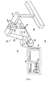
- Fig. 4 shows a schematic view of a structure of one embodiment of the large position measuring apparatus mentioned above.
- a foundation(base) 104 is directly used as the reference surface.
- a vertical direction moving machine of a moving machine 108 is constituted by a guide 128 directly provided on the foundation 104 and a vertical direction moving mechanism 130.
- the change is measured by a relational change measuring mechanism 118, and an influence of the error is removed by the error corrector 120. Accordingly, it is possible to achieve the second object of the present invention, that is, the accuracy is not reduced due to the change of the base.
- an automatic volumetric measuring accuracy correction apparatus can be easily constructed by using one set of the reference side and measurement side angle meters, the interface 126, the controller 122 and the data processor 124.
- the y axis pitching raw data and the y axis yaw raw data can be collected by automatically moving the vertical direction moving mechanism 130 in the y axis moving range at fixed intervals or optional timings such as every day, every one month and every half year.
- the angle errors in the respective portions in the y axis moving range are calculated on the basis of the data, thereby correcting the compensation parameter compensating the positional coordinate by the error corrector 120.
- the structure is made such that the geometrical error measuring instrument 114 is provided.
- the structure may be made such that the geometrical error measuring apparatus is provided in the external portion, the compensation parameter is computed on the basis of the positional coordinate from the positional coordinate computer, and the compensation parameter is stored in the memory in the position measuring apparatus.
- the error compensator 116 can execute the volumetric measuring accuracy correction with respect to the positional coordinate by the positional coordinate corresponding to the output of the positional coordinate computer 110, and the compensation parameter read out from the memory.
- the error corrector 120 can also correct the compensation parameter on the basis of the error correcting data stored in the memory, or further correct the positional coordinate compensated the space accuracy by the compensation parameter so as to execute an accurate volumetric measuring accuracy correction. Since the geometrical error measuring apparatus provided in the external portion is not required for the present position measuring apparatus after the compensation parameter is stored in the memory in the position measuring apparatus, it can be taken out. Accordingly, there is an advantage that the structure can be made simpler.
- a stable accuracy at a time of delivery can be maintained by the automatic volumetric measuring accuracy correction apparatus even in the case that the base is deformed due to the deterioration with age or the temperature fluctuation.
- the stable accuracy can be maintained by the automatic space accuracy compensating apparatus even in the case that the base on which the Coordinate Measuring Machine or the like is placed is changed.
- the present invention can be also applied to an vision measuring machine which moves a image device such as a camera within an orthogonal plane so as to execute a two-dimensional measurement of the workpiece, and a working apparatus such as a machine tool. Accordingly, it is possible to always apply a volumetric measuring accuracy correction having a high accuracy.
Landscapes
- Physics & Mathematics (AREA)
- General Physics & Mathematics (AREA)
- Length Measuring Devices With Unspecified Measuring Means (AREA)
- A Measuring Device Byusing Mechanical Method (AREA)
Claims (11)
- Eine Positionsmessvorrichtung (2) bestehend aus:einem Zielpositionsdetektor (6) zur Feststellung einer Zielposition in einem Koordinatenraum hinsichtlich einer vorbestimmten Bezugsfläche (4);einer verfahrbaren Maschine (8), die sich entsprechend einem vorbestimmten Verhältnis hinsichtlich der Bezugsfläche bewegt, damit der genannte Zielpositionsdetektor bewegt wird, damit die Zielposition durch den genannten Zielpositionsdetektor festgestellt wird;einem Positionskoordinatencomputer (10) zum Errechnen einer Positionskoordinate der Zielposition basierende auf Daten, wie z.B. die Versetzung der genannten verfahrbaren Maschine;einer Positionskoordinatenmessvorrichtung (12), die aus dem genannten Zielpositionsdetektor, der genannten verfahrbaren Maschine und dem genannten Positionskoordinatencomputer besteht;einem Speicher (14), der geometrische Fehler basierend auf einer Positionskoordinate, die von der genannte Positionskoordinatenmessvorrichtung gemessen wurden, klassifiziert und Kompensationsparameter speichert, die von den jeweiligen klassifizierten Fehlern bestimmt werden;einem Fehlerkompensator (16) zum Ablesen der Kompensationsparameter zur Kompensation der Fehler; und wobei die Zielposition innerhalb eine spezifischen Koordinatenraums basierend auf einem Koordinatensystem gemessen wird,wobei die Positionsmessvorrichtung Folgendes umfasst:einen Detektor (18), der misst, ob oder nicht eine Veränderung in einem Verhältnis hinsichtlich der genannten Bezugsfläche durch eine Bewegung der genannten verfahrbaren Maschine eingetreten ist; undeinen Fehlerkorrektor (20) zur Korrektur von zumindest einer der Kompensationsparameter zur Kompensation der Positionskoordinaten durch den genannten Fehlerkompensator und der Positionskoordinate, die durch den genannten Fehlerkompensator kompensiert wurde, um eine Beeinflussung der Positionskoordinate zu entfernen, die durch den Positionskoordinatencomputer aufgrund der Änderung eines Verhältnisses hinsichtlich der genannten Bezugsfläche durch eine Bewegung der genannten verfahrbaren Maschine errechnet wurde, basierend auf einem Änderungsbetrag des Verhältnisses, der durch den genannten Detektor gemessen wurde, falls eine Änderung eingetreten ist.
- Eine Positionsmessvorrichtung entsprechend Anspruch 1, wobei das genannte Koordinatensystem ein rechteckiges XYZ-Koordinatensystem ist, wobei das genannte Koordinatensystem in vertikaler, horizontaler und Höhenrichtung verläuft.
- Eine Positionsmessvorrichtung entsprechend Anspruch 2, wobei die genannte verfahrbare Maschine folgendes umfasst:eine Maschine, die sich in horizontaler Richtung bewegt, damit sie sich entsprechend mit der oder parallel zur X-Achse bewegen kann;eine Maschine, die sich in vertikaler Richtung bewegt, damit sie sich entsprechend mit der oder parallel zur Y-Achse bewegen kann;eine Maschine, die sich in Höhenrichtung bewegt, damit sie sich entsprechend mit der oder parallel zur Z-Achse bewegen kann; undwobei der genannte Detektor in jeder der genannten sich in vertikaler Richtung bewegenden Maschine, der genannten sich in horizontaler Richtung bewegenden Maschine und der genannten sich in Höhenrichtung bewegenden Maschine vorgesehen ist.
- Eine Vorrichtung entsprechend einem der Ansprüche 1 bis 3, wobei sich der genannte Detektor aus einem Seitenwinkelbezugsmesser und einem Seitenwinkelmesser zum Messen zusammensetzt.
- Eine Positionsmessvorrichtung entsprechend Anspruch 4, wobei die genannte verfahrbare Maschine folgendes umfasst:eine sich in vertikaler Richtung bewegende Maschine, die aus einer geraden Führung auf der Bezugsfläche und einem sich in vertikaler Richtung bewegenden Mechanismus, der sich entlang der genannten Führung bewegen kann, besteht;eine sich in horizontaler Richtung bewegende Maschine, die aus einer geraden Führung, die oben an der genannten sich in vertikaler Richtung bewegenden Maschine montiert ist und in einer Richtung parallel zur Bezugsfläche und orthogonal zur Bewegungsrichtung der sich in vertikaler Richtung bewegenden Maschine vorgesehen ist, sowie einem sich horizontaler Richtung bewegenden Mechanismus, der sich entlang der Führung bewegt, besteht; undeine sich in Höhenrichtung bewegende Maschine, die aus einem stangenartigen Element, das an der genannten sich in horizontaler Richtung bewegenden Maschine montiert ist und an einer Spitze mit dem genannten Zielpositionsdetektor versehen ist, und einem sich in Höhenrichtung bewegenden Mechanismus, der das genannte stangenartige Element in eine Richtung orthogonal zur Bezugsfläche bewegt, besteht;wobei die sich in vertikaler Richtung bewegende Maschine den genannten Zielpositionsdetektor auf einer spezifizierten geraden Linie auf der Bezugsfläche bewegt;die sich in horizontaler Richtung bewegende Maschine sich innerhalb einer Fläche bewegt, die orthogonal zur Bewegungsrichtung der genannten sich in vertikaler Richtung bewegenden Maschine und parallel zur Bezugsfläche ist;die sich in Höhenrichtung bewegenden Maschine ein vorbestimmtes Verhältnis hinsichtlich zur Bezugsfläche hat, indem sie sich in einer Richtung bewegt, die orthogonal zur Bezugsfläche ist; undsich der genannte Detektor aus einem Seitenwinkelbezugsmesser, der auf einer Führung der sich in vertikaler Richtung bewegenden Maschine vorgesehen ist, und einem Seitenwinkelmesser zum Messen, der auf dem sich in vertikaler Richtung bewegenden Mechanismus vorgesehen ist, zusammensetzt.
- Eine Vorrichtung entsprechend Anspruch 4 oder Anspruch 5, wobei der genannte Winkelmesser eine zweiachsige Winkellibelle ist.
- Eine Vorrichtung entsprechend Anspruch 4 oder Anspruch 5, wobei der genannte Winkelmesser eine Laserwinkellibelle ist.
- Eine Vorrichtung entsprechend einem der vorhergehenden Ansprüche, wobei das genannte Koordinatensystem ein zweiachsiges, rechteckiges Koordinatensystem ist.
- Eine Positionsmessvorrichtung entsprechend Anspruch 8, wobei ein Änderungsbetrag des durch den genannten Detektor gemessenen Verhältnisses einen Steigungsfehler und einen Kursabweichungsfehler hinsichtlich der Achse in einer spezifizierten linearen Richtung mit einbezieht.
- Eine Vorrichtung entsprechend einem der vorhergehenden Ansprüche, wobei zudem ein Speicher zum Speichern eines Änderungsbetrags des durch den genannten Detektor gemessenen Verhältnisses vorgesehen ist, und wobei der genannte Detektor abnehmbar ist.
- Ein Bearbeitungsapparat bestehend aus der Positionsmessvorrichtung entsprechend einem der vorhergehenden Ansprüche.
Applications Claiming Priority (2)
| Application Number | Priority Date | Filing Date | Title |
|---|---|---|---|
| JP2001060811 | 2001-03-05 | ||
| JP2001060811A JP3634275B2 (ja) | 2001-03-05 | 2001-03-05 | 位置測定装置 |
Publications (3)
| Publication Number | Publication Date |
|---|---|
| EP1239263A2 EP1239263A2 (de) | 2002-09-11 |
| EP1239263A3 EP1239263A3 (de) | 2003-07-23 |
| EP1239263B1 true EP1239263B1 (de) | 2014-09-24 |
Family
ID=18920187
Family Applications (1)
| Application Number | Title | Priority Date | Filing Date |
|---|---|---|---|
| EP02251471.5A Expired - Lifetime EP1239263B1 (de) | 2001-03-05 | 2002-03-01 | Positionsmessvorrichtung und Bearbeitungsapparat mit dieser Vorrichtung |
Country Status (4)
| Country | Link |
|---|---|
| US (1) | US6671650B2 (de) |
| EP (1) | EP1239263B1 (de) |
| JP (1) | JP3634275B2 (de) |
| CN (1) | CN1200248C (de) |
Families Citing this family (26)
| Publication number | Priority date | Publication date | Assignee | Title |
|---|---|---|---|---|
| DE10138138A1 (de) * | 2001-08-09 | 2003-02-20 | Zeiss Carl | Korrektur des Temperaturfehlers bei einer Messung mit einem Koordinatenmessgerät |
| JP2004125637A (ja) * | 2002-10-03 | 2004-04-22 | Sony Corp | 情報処理システムおよび方法、情報処理装置および方法、並びにプログラム |
| DE10339194B4 (de) * | 2003-08-22 | 2006-06-29 | Bundesrepublik Deutschland, vertr. d. d. Bundesministerium für Wirtschaft und Technologie, dieses vertr. d. d. Präsidenten der Physikalisch-Technischen Bundesanstalt | Verfahren zur Ermittlung systematischer geometrischer Abweichungen in technischen Mehrkörpersystemen |
| JP4675047B2 (ja) * | 2004-02-02 | 2011-04-20 | 株式会社ミツトヨ | 三次元測定機の測定座標補正方法及び三次元測定システム |
| CN100462677C (zh) * | 2005-07-08 | 2009-02-18 | 鸿富锦精密工业(深圳)有限公司 | 三坐标测量机床误差补偿系统及方法 |
| DE102007004971A1 (de) * | 2007-01-26 | 2008-08-07 | Afm Technology Gmbh | Vorrichtung und Verfahren zur Korrektur eines Positionierungssystems |
| WO2009013768A1 (en) * | 2007-07-24 | 2009-01-29 | Hexagon Metrology S.P.A. | Method of compensating measurement errors of a measuring machine deriving from the deformations of the machine bed caused by the load exerted by the mobile unit of the machine on the machine bed, and measuring machine operating according to said method |
| JP5424581B2 (ja) * | 2008-06-06 | 2014-02-26 | キヤノン株式会社 | 部分測定を合成する形状測定方法 |
| JP5297818B2 (ja) * | 2009-01-06 | 2013-09-25 | 株式会社ミツトヨ | 三次元測定機 |
| US20100299094A1 (en) * | 2009-05-23 | 2010-11-25 | Carmar Technology Co., Ltd. | Thermal deformation error compensation method for coordinate measuring machine |
| KR101658576B1 (ko) * | 2010-01-15 | 2016-09-22 | 삼성전자주식회사 | 이미지 데이터를 이용한 거리 측정 장치 및 방법 |
| JP5486416B2 (ja) * | 2010-06-18 | 2014-05-07 | 株式会社ミツトヨ | 産業機械 |
| JP5557620B2 (ja) | 2010-06-29 | 2014-07-23 | 株式会社ミツトヨ | 形状測定装置 |
| US10977601B2 (en) | 2011-06-29 | 2021-04-13 | State Farm Mutual Automobile Insurance Company | Systems and methods for controlling the collection of vehicle use data using a mobile device |
| US20130006674A1 (en) | 2011-06-29 | 2013-01-03 | State Farm Insurance | Systems and Methods Using a Mobile Device to Collect Data for Insurance Premiums |
| CN103134451A (zh) * | 2011-11-30 | 2013-06-05 | 鸿富锦精密工业(深圳)有限公司 | 三坐标测量机三轴垂直度误差补偿系统及方法 |
| JP6025386B2 (ja) * | 2012-05-02 | 2016-11-16 | キヤノン株式会社 | 画像計測装置、画像計測方法及び画像計測プログラム |
| JP6463926B2 (ja) * | 2014-08-28 | 2019-02-06 | 三菱重工工作機械株式会社 | 工作機械の変位補正システム |
| DE102015217206A1 (de) * | 2014-09-16 | 2016-03-17 | Kabushiki Kaisha Toshiba | Datenkompensationsvorrichtung, datenkompensationsverfahren und bearbeitungsvorrichtung |
| CN106041930B (zh) * | 2016-06-27 | 2019-10-15 | 长沙长泰机器人有限公司 | 具有工件位置补偿功能的机加工系统及控制方法 |
| JP6840585B2 (ja) * | 2017-03-21 | 2021-03-10 | 株式会社ミツトヨ | 測定システム、測定プログラム及び制御方法 |
| CN107052646B (zh) * | 2017-03-23 | 2019-07-30 | 宁波金凤焊割机械制造有限公司 | 一种钢管束的焊接跟踪装置 |
| CN106990753B (zh) * | 2017-03-27 | 2019-12-31 | 安徽省捷甬达智能机器有限公司 | 一种基于校准体积的机床位移补偿方法和系统 |
| CN113950650A (zh) * | 2019-06-12 | 2022-01-18 | 三菱电机株式会社 | 调整量推定装置、调整量推定方法及调整量推定程序 |
| CN113021077A (zh) * | 2019-12-09 | 2021-06-25 | 北京精雕科技集团有限公司 | 一种数控机床在机测量系统的精度校准方法 |
| CN114872211B (zh) * | 2022-07-08 | 2022-10-25 | 沈阳和研科技有限公司 | 一种双轴划片机的y轴的自动补偿方法及双轴划片机 |
Family Cites Families (14)
| Publication number | Priority date | Publication date | Assignee | Title |
|---|---|---|---|---|
| FR2330997A1 (fr) | 1975-11-07 | 1977-06-03 | Sagem | Perfectionnements aux procedes et machines de mesure des dimensions de pieces |
| JPS6197504A (ja) * | 1984-10-19 | 1986-05-16 | Yamazaki Mazak Corp | 三次元位置測定方法及び装置 |
| US4663852A (en) * | 1985-09-19 | 1987-05-12 | Digital Electronic Automation, Inc | Active error compensation in a coordinated measuring machine |
| US4819195A (en) | 1987-01-20 | 1989-04-04 | The Warner & Swasey Company | Method for calibrating a coordinate measuring machine and the like and system therefor |
| JP2520202B2 (ja) | 1991-07-03 | 1996-07-31 | 株式会社ミツトヨ | 測定値評価方法 |
| JP2902205B2 (ja) | 1992-03-06 | 1999-06-07 | 株式会社ミツトヨ | 空間誤差補正装置 |
| DE4342312A1 (de) | 1993-12-11 | 1995-06-14 | Zeiss Carl Fa | Verfahren zur Korrektur von schwingungsbedingten Meßfehlern bei Koordinatenmeßgeräten |
| EP0684447B1 (de) * | 1994-05-27 | 2003-09-17 | Carl Zeiss | Koordinatenmessung an Werkstücken mit einer Korrektur des durch die Messkraft abhängigen Biegeverhaltens des Koordinatenmessgerätes |
| DE4421302C1 (de) * | 1994-06-17 | 1995-12-07 | Leitz Mestechnik Gmbh | Verfahren zur Eliminierung des Rollwinkels einer Meßachse einer Koordinatenmeßmaschine sowie Vorrichtung zur Durchführung des Verfahrens |
| JP3531882B2 (ja) * | 1995-03-08 | 2004-05-31 | 株式会社ミツトヨ | 三次元測定機の測定誤差補正装置 |
| JPH109852A (ja) | 1996-06-20 | 1998-01-16 | Nikon Corp | 真直度測定方法 |
| US6041274A (en) * | 1997-04-21 | 2000-03-21 | Shinko Electric Co., Ltd. | Positional deviation detecting device for a mobile body and position correcting apparatus for a working machine mounted on a mobile body |
| DE19830646C2 (de) * | 1998-07-09 | 2003-11-27 | Leitz Messtechnik Gmbh | Verfahren zur Korrektur von geometrischen Ablauffehlern einer Koordinatenmeßmaschine |
| GB0016533D0 (en) * | 2000-07-06 | 2000-08-23 | Renishaw Plc | Method of and apparatus for correction of coordinate measurement errors due to vibrations in coordinate measuring machines (cmms) |
-
2001
- 2001-03-05 JP JP2001060811A patent/JP3634275B2/ja not_active Expired - Fee Related
-
2002
- 2002-02-19 US US10/076,654 patent/US6671650B2/en not_active Expired - Lifetime
- 2002-03-01 EP EP02251471.5A patent/EP1239263B1/de not_active Expired - Lifetime
- 2002-03-04 CN CNB02106699XA patent/CN1200248C/zh not_active Expired - Lifetime
Also Published As
| Publication number | Publication date |
|---|---|
| EP1239263A2 (de) | 2002-09-11 |
| US6671650B2 (en) | 2003-12-30 |
| JP2002257535A (ja) | 2002-09-11 |
| CN1374502A (zh) | 2002-10-16 |
| CN1200248C (zh) | 2005-05-04 |
| JP3634275B2 (ja) | 2005-03-30 |
| EP1239263A3 (de) | 2003-07-23 |
| US20020123858A1 (en) | 2002-09-05 |
Similar Documents
| Publication | Publication Date | Title |
|---|---|---|
| EP1239263B1 (de) | Positionsmessvorrichtung und Bearbeitungsapparat mit dieser Vorrichtung | |
| JP2510216B2 (ja) | 産業用ロボットのセンサを校正するための方法 | |
| EP0275428B1 (de) | Kalibrierungsverfahren für ein Koordinatenmessgerät und ähnliche Geräte | |
| US5333386A (en) | Method of measuring the effective instantaneous position of a slide-mounted probe element or tool | |
| US8786243B2 (en) | Method and device for preparing error map and numerically controlled machine tool having error map preparation function | |
| EP0264223B1 (de) | Anpassung analoger Messsonden | |
| US4663852A (en) | Active error compensation in a coordinated measuring machine | |
| US4587622A (en) | Method and apparatus for determining and correcting guidance errors | |
| CN101918792B (zh) | 用于校准坐标测量装置的方法及其坐标测量机 | |
| US7131207B2 (en) | Workpiece inspection method | |
| US8607466B2 (en) | Coordinate measuring machine (CMM) and method of compensating errors in a CMM | |
| US20050283989A1 (en) | Method of inspecting workpieces on a measuring machine | |
| CN108351203B (zh) | 提供精确坐标测量的方法、独立基准模块和坐标测量机 | |
| US20090024343A1 (en) | Method of determining geometric errors in a machine tool or measuring machine | |
| US20190011327A1 (en) | Cnc machine geometry error and accuracy monitoring and evaluation | |
| CN110530296A (zh) | 一种线激光安装误差角确定方法 | |
| EP2085739B1 (de) | Verfahren zur Messung der Sondengeradheit | |
| US7610162B2 (en) | Method and machine for determining a space coordinate of a measurement point on a measurement object | |
| CN114782513A (zh) | 一种基于平面的点激光传感器安装位姿标定方法 | |
| US9310177B2 (en) | Method of correcting measurement data of a coordinate measuring machine and a coordinate measuring machine | |
| EP0279926B1 (de) | Positionsbestimmungsverfahren innerhalb des Messraumes eines Koordinatenmessgerätes und dergleichen und System dafür | |
| JPH03156307A (ja) | 修正表面検証用可動装置 | |
| CN111443657B (zh) | 一种机台编码器安装偏移的修正方法 | |
| Burdekin et al. | Computer aided calibration of the geometric errors of multi-axis coordinate measuring machines | |
| JP2001005528A (ja) | ステージ装置および位置検出装置 |
Legal Events
| Date | Code | Title | Description |
|---|---|---|---|
| PUAI | Public reference made under article 153(3) epc to a published international application that has entered the european phase |
Free format text: ORIGINAL CODE: 0009012 |
|
| AK | Designated contracting states |
Kind code of ref document: A2 Designated state(s): AT BE CH CY DE DK ES FI FR GB GR IE IT LI LU MC NL PT SE TR |
|
| AX | Request for extension of the european patent |
Free format text: AL;LT;LV;MK;RO;SI |
|
| PUAL | Search report despatched |
Free format text: ORIGINAL CODE: 0009013 |
|
| AK | Designated contracting states |
Designated state(s): AT BE CH CY DE DK ES FI FR GB GR IE IT LI LU MC NL PT SE TR |
|
| AX | Request for extension of the european patent |
Extension state: AL LT LV MK RO SI |
|
| 17P | Request for examination filed |
Effective date: 20040113 |
|
| AKX | Designation fees paid |
Designated state(s): DE GB IT |
|
| 17Q | First examination report despatched |
Effective date: 20090306 |
|
| GRAP | Despatch of communication of intention to grant a patent |
Free format text: ORIGINAL CODE: EPIDOSNIGR1 |
|
| INTG | Intention to grant announced |
Effective date: 20140417 |
|
| RAP1 | Party data changed (applicant data changed or rights of an application transferred) |
Owner name: MITUTOYO CORPORATION |
|
| GRAS | Grant fee paid |
Free format text: ORIGINAL CODE: EPIDOSNIGR3 |
|
| GRAA | (expected) grant |
Free format text: ORIGINAL CODE: 0009210 |
|
| AK | Designated contracting states |
Kind code of ref document: B1 Designated state(s): DE GB IT |
|
| REG | Reference to a national code |
Ref country code: GB Ref legal event code: FG4D |
|
| REG | Reference to a national code |
Ref country code: DE Ref legal event code: R096 Ref document number: 60246652 Country of ref document: DE Effective date: 20141030 |
|
| REG | Reference to a national code |
Ref country code: DE Ref legal event code: R097 Ref document number: 60246652 Country of ref document: DE |
|
| PLBE | No opposition filed within time limit |
Free format text: ORIGINAL CODE: 0009261 |
|
| STAA | Information on the status of an ep patent application or granted ep patent |
Free format text: STATUS: NO OPPOSITION FILED WITHIN TIME LIMIT |
|
| 26N | No opposition filed |
Effective date: 20150625 |
|
| PGFP | Annual fee paid to national office [announced via postgrant information from national office to epo] |
Ref country code: IT Payment date: 20210329 Year of fee payment: 20 |
|
| PGFP | Annual fee paid to national office [announced via postgrant information from national office to epo] |
Ref country code: GB Payment date: 20210324 Year of fee payment: 20 Ref country code: DE Payment date: 20210319 Year of fee payment: 20 |
|
| REG | Reference to a national code |
Ref country code: DE Ref legal event code: R071 Ref document number: 60246652 Country of ref document: DE |
|
| REG | Reference to a national code |
Ref country code: GB Ref legal event code: PE20 Expiry date: 20220228 |
|
| PG25 | Lapsed in a contracting state [announced via postgrant information from national office to epo] |
Ref country code: GB Free format text: LAPSE BECAUSE OF EXPIRATION OF PROTECTION Effective date: 20220228 |