EP1239215B1 - Lighting device for illuminating rooms - Google Patents
Lighting device for illuminating rooms Download PDFInfo
- Publication number
- EP1239215B1 EP1239215B1 EP02005485A EP02005485A EP1239215B1 EP 1239215 B1 EP1239215 B1 EP 1239215B1 EP 02005485 A EP02005485 A EP 02005485A EP 02005485 A EP02005485 A EP 02005485A EP 1239215 B1 EP1239215 B1 EP 1239215B1
- Authority
- EP
- European Patent Office
- Prior art keywords
- light
- hollow body
- wall
- scattering
- luminary
- Prior art date
- Legal status (The legal status is an assumption and is not a legal conclusion. Google has not performed a legal analysis and makes no representation as to the accuracy of the status listed.)
- Expired - Lifetime
Links
- 238000000149 argon plasma sintering Methods 0.000 claims abstract description 25
- 230000003287 optical effect Effects 0.000 claims description 9
- 239000000463 material Substances 0.000 claims description 5
- 230000000149 penetrating effect Effects 0.000 abstract 1
- 238000005286 illumination Methods 0.000 description 17
- 238000009826 distribution Methods 0.000 description 12
- 230000000694 effects Effects 0.000 description 12
- 230000003595 spectral effect Effects 0.000 description 8
- 230000002349 favourable effect Effects 0.000 description 6
- 230000005855 radiation Effects 0.000 description 4
- 238000010521 absorption reaction Methods 0.000 description 3
- 230000004907 flux Effects 0.000 description 3
- 230000005540 biological transmission Effects 0.000 description 2
- 238000000576 coating method Methods 0.000 description 2
- 239000003086 colorant Substances 0.000 description 2
- 230000004313 glare Effects 0.000 description 2
- 238000010438 heat treatment Methods 0.000 description 2
- 230000001795 light effect Effects 0.000 description 2
- QSHDDOUJBYECFT-UHFFFAOYSA-N mercury Chemical compound [Hg] QSHDDOUJBYECFT-UHFFFAOYSA-N 0.000 description 2
- 229920001343 polytetrafluoroethylene Polymers 0.000 description 2
- 239000004810 polytetrafluoroethylene Substances 0.000 description 2
- 230000002411 adverse Effects 0.000 description 1
- 238000013459 approach Methods 0.000 description 1
- 230000015572 biosynthetic process Effects 0.000 description 1
- 238000001816 cooling Methods 0.000 description 1
- 230000007423 decrease Effects 0.000 description 1
- 238000007688 edging Methods 0.000 description 1
- 238000005516 engineering process Methods 0.000 description 1
- 238000000605 extraction Methods 0.000 description 1
- 238000005304 joining Methods 0.000 description 1
- 229910052753 mercury Inorganic materials 0.000 description 1
- 239000000203 mixture Substances 0.000 description 1
- 239000004033 plastic Substances 0.000 description 1
- 229920003023 plastic Polymers 0.000 description 1
- 239000011112 polyethylene naphthalate Substances 0.000 description 1
- -1 polytetrafluoroethylene Polymers 0.000 description 1
- 238000002310 reflectometry Methods 0.000 description 1
- 238000005096 rolling process Methods 0.000 description 1
- 239000004065 semiconductor Substances 0.000 description 1
- 230000035939 shock Effects 0.000 description 1
- 238000001228 spectrum Methods 0.000 description 1
- 238000002834 transmittance Methods 0.000 description 1
- 238000009827 uniform distribution Methods 0.000 description 1
Images


Classifications
-
- F—MECHANICAL ENGINEERING; LIGHTING; HEATING; WEAPONS; BLASTING
- F21—LIGHTING
- F21V—FUNCTIONAL FEATURES OR DETAILS OF LIGHTING DEVICES OR SYSTEMS THEREOF; STRUCTURAL COMBINATIONS OF LIGHTING DEVICES WITH OTHER ARTICLES, NOT OTHERWISE PROVIDED FOR
- F21V7/00—Reflectors for light sources
- F21V7/22—Reflectors for light sources characterised by materials, surface treatments or coatings, e.g. dichroic reflectors
-
- F—MECHANICAL ENGINEERING; LIGHTING; HEATING; WEAPONS; BLASTING
- F21—LIGHTING
- F21S—NON-PORTABLE LIGHTING DEVICES; SYSTEMS THEREOF; VEHICLE LIGHTING DEVICES SPECIALLY ADAPTED FOR VEHICLE EXTERIORS
- F21S11/00—Non-electric lighting devices or systems using daylight
-
- F—MECHANICAL ENGINEERING; LIGHTING; HEATING; WEAPONS; BLASTING
- F21—LIGHTING
- F21S—NON-PORTABLE LIGHTING DEVICES; SYSTEMS THEREOF; VEHICLE LIGHTING DEVICES SPECIALLY ADAPTED FOR VEHICLE EXTERIORS
- F21S19/00—Lighting devices or systems employing combinations of electric and non-electric light sources; Replacing or exchanging electric light sources with non-electric light sources or vice versa
-
- F—MECHANICAL ENGINEERING; LIGHTING; HEATING; WEAPONS; BLASTING
- F21—LIGHTING
- F21V—FUNCTIONAL FEATURES OR DETAILS OF LIGHTING DEVICES OR SYSTEMS THEREOF; STRUCTURAL COMBINATIONS OF LIGHTING DEVICES WITH OTHER ARTICLES, NOT OTHERWISE PROVIDED FOR
- F21V7/00—Reflectors for light sources
- F21V7/0008—Reflectors for light sources providing for indirect lighting
-
- F—MECHANICAL ENGINEERING; LIGHTING; HEATING; WEAPONS; BLASTING
- F21—LIGHTING
- F21S—NON-PORTABLE LIGHTING DEVICES; SYSTEMS THEREOF; VEHICLE LIGHTING DEVICES SPECIALLY ADAPTED FOR VEHICLE EXTERIORS
- F21S8/00—Lighting devices intended for fixed installation
- F21S8/04—Lighting devices intended for fixed installation intended only for mounting on a ceiling or the like overhead structures
-
- F—MECHANICAL ENGINEERING; LIGHTING; HEATING; WEAPONS; BLASTING
- F21—LIGHTING
- F21V—FUNCTIONAL FEATURES OR DETAILS OF LIGHTING DEVICES OR SYSTEMS THEREOF; STRUCTURAL COMBINATIONS OF LIGHTING DEVICES WITH OTHER ARTICLES, NOT OTHERWISE PROVIDED FOR
- F21V13/00—Producing particular characteristics or distribution of the light emitted by means of a combination of elements specified in two or more of main groups F21V1/00 - F21V11/00
- F21V13/02—Combinations of only two kinds of elements
- F21V13/04—Combinations of only two kinds of elements the elements being reflectors and refractors
-
- F—MECHANICAL ENGINEERING; LIGHTING; HEATING; WEAPONS; BLASTING
- F21—LIGHTING
- F21W—INDEXING SCHEME ASSOCIATED WITH SUBCLASSES F21K, F21L, F21S and F21V, RELATING TO USES OR APPLICATIONS OF LIGHTING DEVICES OR SYSTEMS
- F21W2131/00—Use or application of lighting devices or systems not provided for in codes F21W2102/00-F21W2121/00
- F21W2131/40—Lighting for industrial, commercial, recreational or military use
- F21W2131/402—Lighting for industrial, commercial, recreational or military use for working places
-
- F—MECHANICAL ENGINEERING; LIGHTING; HEATING; WEAPONS; BLASTING
- F21—LIGHTING
- F21Y—INDEXING SCHEME ASSOCIATED WITH SUBCLASSES F21K, F21L, F21S and F21V, RELATING TO THE FORM OR THE KIND OF THE LIGHT SOURCES OR OF THE COLOUR OF THE LIGHT EMITTED
- F21Y2103/00—Elongate light sources, e.g. fluorescent tubes
- F21Y2103/30—Elongate light sources, e.g. fluorescent tubes curved
- F21Y2103/33—Elongate light sources, e.g. fluorescent tubes curved annular
-
- F—MECHANICAL ENGINEERING; LIGHTING; HEATING; WEAPONS; BLASTING
- F21—LIGHTING
- F21Y—INDEXING SCHEME ASSOCIATED WITH SUBCLASSES F21K, F21L, F21S and F21V, RELATING TO THE FORM OR THE KIND OF THE LIGHT SOURCES OR OF THE COLOUR OF THE LIGHT EMITTED
- F21Y2113/00—Combination of light sources
- F21Y2113/10—Combination of light sources of different colours
- F21Y2113/13—Combination of light sources of different colours comprising an assembly of point-like light sources
-
- F—MECHANICAL ENGINEERING; LIGHTING; HEATING; WEAPONS; BLASTING
- F21—LIGHTING
- F21Y—INDEXING SCHEME ASSOCIATED WITH SUBCLASSES F21K, F21L, F21S and F21V, RELATING TO THE FORM OR THE KIND OF THE LIGHT SOURCES OR OF THE COLOUR OF THE LIGHT EMITTED
- F21Y2115/00—Light-generating elements of semiconductor light sources
- F21Y2115/10—Light-emitting diodes [LED]
Definitions
- the present invention relates to a luminous element for illuminating rooms with a hollow body bounded by a wall, which is provided for multiple reflection of light inside with reflective inner surfaces, wherein the inner surfaces of the hollow body have a reflectance of at least 90% and are designed to be light scattering and in the Wall of the hollow body is provided at least one wall which passes through the light exit opening.
- Luminaires for the illumination of rooms are known in the prior art in a wide variety and with various forms.
- the different forms of luminaires depend on the way they are used. Here you can generally distinguish between luminaires, which serve the selective illumination of a particular area.
- luminaires which serve the selective illumination of a particular area.
- Another type of luminaires serves the most uniform possible illumination of premises.
- ceiling lights, arrangement of fluorescent tubes, etc. are often used.
- the task of the selective illumination of certain limited areas as well as the uniform illumination of rooms often occurs simultaneously in closed rooms.
- various types of luminous bodies often have to be used in combination to solve these problems.
- the documents DE 4 439 507 A1 and US Pat. No. 4,459,642 A disclose luminous bodies with hollow bodies in which the hollow bodies have reflective inner surfaces. In the luminous bodies shown in these documents, both sunlight and artificial light is irradiated. In the hollow body there is a leveling or mixing of the light radiated by the different light sources. This leveling is based on a multiple reflection of the incident light in the hollow body, on its reflective inner surfaces. In US Pat. No. 4,459,642 A, the light emission from the luminous element takes place via semi-transparent regions in the wall of the hollow body and in DE 4 439 507 A1 via so-called light exit systems, in which the light can also emerge via semi-transparent regions.
- All the luminous bodies shown in these documents have the disadvantage that, although they are not used for uniform and sufficiently bright room illumination, they are not suitable for the purpose of illuminating limited subareas with increased light requirements, such as, for example. can be used to illuminate workplaces.
- the luminance produced in the respective hollow bodies is not sufficient in the case of the above-mentioned luminous bodies known from the prior art.
- GB 2340215 A discloses a generic luminous element for illuminating rooms with a hollow body bounded by a wall, which is provided for multiple reflection of light inside with reflective inner surfaces, wherein the inner surfaces of the hollow body have a reflectance of at least 90% and are designed to light scattering and in the wall of the hollow body at least one wall which passes through the light exit opening is provided.
- the object of the invention is to further improve the effectiveness of the generic luminous body.
- the luminous body has a wall of the hollow body which passes through the light exit opening.
- This targeted light extraction can be used for concentrated illumination of limited areas, but also for the targeted illumination of rooms.
- overall a significantly improved illumination is achieved than with the known in the prior art hollow body lamps.
- the use of light exit openings is possible only by a sufficiently high luminance in the interior of the luminous element.
- the high luminance and thus an economical operation of such lamps with a corresponding high luminaire efficiency is only possible by the inventive reflectance of the inner surfaces of the hollow body of at least 90%. Due to the light-scattering design of the inner surfaces of the hollow body is also achieved on the one hand, that light sources or other components within the hollow body are not displayed to the outside.
- the light-scattering effect of the inner surfaces results in that only diffusely diffused light is radiated from the luminous body. Under light scattering not only a perfect direction independent ideal scattering but in general an expansion of the reflected light beam is called. Overall, the light-scattering effect according to the invention is characterized in that the light leaving the luminous element no longer has preferred directions. This can, as stated below, be achieved by various measures.
- the ratio of the inner surface of the wall of the hollow body to the sum of all surfaces of all openings, preferably all light exit openings in the wall of the hollow body is greater than 5: 1, preferably greater than 10: 1, is.
- a ratio of the surface of the wall of the hollow body to the sum of all surfaces of all openings in the wall of the hollow body greater than 20: 1 or greater than 30: 1 or preferably even greater than 40: 1 strive.
- a luminous element can only be operated effectively if its efficiency Eta is above a certain minimum value.
- the efficiency Eta depends on the inner surface of the wall of the sum of all surfaces of all openings and the reflectance of the inner surfaces.
- the efficiency Eta depends on the inner surface of the wall of the sum of all surfaces of all openings and the reflectance of the inner surfaces.
- the efficiency Eta is generally defined as the ratio of the luminous flux which exits the hollow body through A1 to the luminous flux of the feeding light sources.
- the area of the light exit opening (s) to be kept as small as possible, since this further simplifies the directing of the light flux emitted by the light exit openings through a corresponding optical system. This is the case, for example, if further light-directing reflectors are to be used. From the above formula for the efficiency Eta results, for example, that when a Efficiency of 65% with the known in the prior art good reflectance of about 85% should be achieved, the area ratio f should be more than 32%.
- the result for the area ratio f is a value of 9.7%, which in turn means that the surface of the light exit openings can be kept much smaller thanks to the high reflectance, without sacrificing the efficiency in Purchase would have to be taken. With correspondingly higher degrees of reflection, correspondingly smaller light exit openings can be used with constant efficiency.
- a preferred embodiment of the filament according to the invention provides that in the luminous body at least one light inlet opening preferably to the inlet of daylight and / or sunlight and / or at least one artificial light source is arranged.
- the hollow body with a diffusely reflecting inner surface can also have one or more light entry opening (s) in order to feed natural or artificial light from outside through the openings into the hollow body as an alternative or in addition to an integrated light source. Due to the multiple reflection of the light on the inner surfaces of the hollow body, the position of the light entry opening or the artificial light source in the hollow body of the luminous element is independent of the overall luminous effect emitted by the luminous element. This allows a very great freedom in the design of the shape of the filament.
- the light distribution emerging from the light exit opening is always diffused and independent of the light distribution of the light source located in the hollow body and independent of the light distribution of the light source flowing through the inlet opening. If both natural and artificial light is irradiated into the hollow body, it can be maintained by a corresponding control of the proportion of artificial light, a nearly uniform intensity of the light emitted by the lamp with maximum sunlight proportion over the entire daily routine indoors.
- a preferred embodiment provides that two or more light sources or light inlet openings, preferably for the entrance of daylight and / or sunlight are arranged in the luminous body, wherein the multiple reflection at the highly reflective inner surfaces, the light introduced into the hollow body, preferably almost completely, mixes.
- differently colored light whether it is irradiated by one or different light sources in the hollow body of the filament, mixed in the way by multiple reflections of the light on the inner surfaces of the hollow body, that it always leaves the light exit surfaces as a mixed light, preferably white light.
- daylight with artificial light or different colored light from different light sources in the hollow body of the luminous body can be mixed specifically.
- an inventive embodiment of the luminous element can also be used to eliminate the directional dependence of the intensity of the light, which is caused by the emission characteristic of a light source.
- a preferred embodiment provides that at least one light source is provided which emits light of different intensity in different spatial directions, wherein the multiple reflection of the light at the highly reflective inner surface of the hollow body leads to the fact that the intensity of the luminous body - preferably via at least one light exit opening - emitted light is completely independent of direction.
- each light source parallel sunlight, diffused fluorescent light, incandescent light, etc.
- a "diffused surface light source” regardless of their original radiation characteristics, which - is easy to control - preferably with reflectors.
- the achieved by the multiple reflection leveling the intensity, the direction and the color content of the light emitted by the light source or sources is particularly favorable for the use of different-colored point and line light sources or different colored high-pressure discharge lamps.
- the leveling effect can also be used with the use of multiple semiconductor light sources (e.g., LEDs).
- the highly reflective properties of the inner surface of the hollow body according to the invention can, as stated above, be achieved by various measures.
- a preferred variant provides that the light-scattering highly reflective inner surfaces at least partially, preferably completely, have a light-diffusing preferably white film.
- a white film can be made, for example, from polytetrafluoroethylene (PTFE).
- PTFE polytetrafluoroethylene
- the light-scattering highly reflecting inner surfaces at least partially, preferably completely have a light-scattering roughened, frosted or etched surface.
- the light-scattering highly reflective inner surfaces at least partially preferably a completely - preferably formed of knobs, Learnfachkantung, grooves or other straight or oblique irregularities formed light-scattering macroscopic surface structure.
- the macroscopic surface structure consists of glossy or high-gloss material.
- An example of this variant is e.g. It is to use a high-gloss film or a high-gloss reflector sheet, the surface of which is grooved, grooved, creased multiple or the like. In this way, reflectivities of the inner surfaces of the hollow body greater than 95% or 98% can be achieved.
- all these different variants of the design of the highly reflective light-scattering inner surfaces have in common that the light ultimately leaving the luminous body through the light exit opening is pleasantly diffused.
- a particularly preferred embodiment provides that at least one light-guiding, preferably parabolically shaped, mirror optics or another light-deflecting device is arranged in the region of the light exit opening of the luminous element and limits the exiting light angularly.
- refractor optics or diffractor optics may also be used.
- diaphragms can also be provided in the interior of the hollow body, these diaphragms preventing the direct view of the light source or the light inlet opening in the hollow body.
- a preferred embodiment of the luminous body according to the invention provides that it has a preferably diffusely scattering, for the non-reflected light component substantially translucent wall. This creates a particularly uniform and pleasant illumination of a room. Due to the high reflectance generated, highly concentrated luminance within the Cavity of the filament extends from the very small not reflected on the inner surface of the hollow body but transmitted through the wall diffusely scattered light component for a pleasant for the human eye uniform illumination of a room. As a result of the transmission of the non-reflecting residual light through the wall, the efficiency of the luminous element is further increased since almost the entire light, which is also always fed in, leaves the luminous element as useful light.
- the wall or the luminous body absorbs as little light energy in the form of heat.
- the low heat absorption can be achieved by a high degree of transmittance.
- a good transmission of the infrared wavelength ranges of the light is in the foreground.
- cooling fins or the like may be provided on the hollow body.
- another variant provides thermal shock protection e.g. in the form of mesh, plastic ribs or the like.
- the luminous element is a preferably cuboidal hollow body, which is lined with a highly reflective film, wherein in the hollow body at least one lamp or at least one light inlet opening, - preferably for daylight and / or sunlight - and at least one aperture is arranged , wherein the direct radiation component hidden is.
- Fig. 1 shows a simple incandescent lamp in which no light is emitted in the direction of the socket of the incandescent lamp.
- This is a schematic example of the fact that light sources typically have a directionality in the radiated intensity of the light.
- Fig. 2 this is illustrated by means of a light source 2 located in a light source 1.
- the light source 1 in FIG. 2 emits light of different intensity in different directions. This ultimately results in the fact that in the angular range perpendicularly below the light source 1 or the light exit opening 3 of the luminous element 2 light is emitted with a relatively high intensity.
- the light beam 4 In contrast, the intensity of the emitted light decreases with increasing angle against the illustrated by beam 4 vertical radiation direction. This reduces the light intensity towards the sides.
- This laterally emitted light of lower intensity is represented by the beams 5 and 6 by way of example.
- FIG. 3 On the basis of a schematic representation of a luminous body with a discharge lamp.
- a discharge lamp 8 forms at the bottom of a lamp sump 9. This changes the spectral content (color) of the light passing through it.
- the light generated by the gas discharge lamp is filtered as it passes through the lamp sump 9 so that it leaves the gas discharge lamp down as a brown light.
- Such a light beam with brown light is shown schematically as beam 10 in FIG.
- the beam path 11 does not pass through the lamp sump and thus the light passing along its path is not filtered by the lamp sump. It leaves on its way via a reflection on the reflector 7, the gas discharge lamp as blue light.
- the total light effect of such a luminous element is thus characterized by the fact that disturbing color spots exist on the use plane 12, since the use plane 12 is illuminated in regions with differently colored light.
- the light emitted by the light source 13 is reflected a plurality of times at the light-scatteringly highly reflective inner surface 14 of the hollow body 15 before part of the light leaves the luminous body through the light exit opening 16.
- the light-scattering highly reflective properties of the inner surfaces 14 can in all embodiments, e.g. be achieved by suitable coatings, macroscopic surface structures or the bonding of suitable films.
- Such films may e.g. polytetraethylene films or multilayer polymeric films having an outer layer of polyethylene naphthalate (PEN).
- a mirror optics 17 or another light-directing device can be attached at the light exit opening 16 at the light exit opening 16. It is provided that a wide variety of mirror grid optics are attached to the light exit opening and thus a variety of different adapted to the particular needs lighting effects can be achieved.
- the diaphragm 18 prevents light from directly leaving the lamp 13 through the light exit opening 16, the luminous body. This prevents a person from being dazzled by light emitted directly from the light source. That by the Light exit opening 16 light leaving the filament has been reflected light-scattering several times before leaving the filament on the highly reflective inner surface 14 and is thus a completely direction independent, spectrally completely mixed, pleasant diffused light.
- diffuse light can also be emitted by the luminous body through the wall of the hollow body 15 when the wall of the hollow body 15 is designed to be translucent. It should be noted that despite the high reflectance of the inner surface 14 of the hollow body 15 sufficient for the illumination of a room amount of light can be transmitted through the highly reflective inner surface and the wall of the hollow body 15, since on a suitable wall whose absorption is negligible and on the other hand, such a high luminance in the interior 19 of the hollow body is produced by the multiple reflection, that the low percentage of the transmitted residual light is still sufficient for pleasant illumination of rooms.
- the ratio between the light exiting through the wall 15 of the luminous element and the amount of light exiting through the light exit opening 16 is essentially determined by the ratio of the area of the light exit opening 16 and the total area of the highly reflective inner wall 14 of the hollow body 15 and can be related to the respective one Need to be adjusted.
- precise control is possible between the proportions of the general room lighting with pleasantly diffused light and the concentrated illumination of limited areas.
- a glare limitation in all spatial directions for angular ranges above 65 ° to the vertical to less than 1000 cd / m 2 can be achieved for office workplaces.
- 5 shows a variant with two light sources 13, in which the hollow body 15 has an overall oval cross-sectional shape and a mirror-grid optical system 17 integrated in the wall.
- 6 shows schematically a variant with a plurality of light exit openings 16.
- FIG. 7 shows an embodiment according to the invention in which parallel sunlight enters the interior 19 of the hollow body 15 through a light entry opening 20.
- the incoming sunlight is transformed into a completely direction-independent diffused light and then exits from the light exit opening 16.
- the wall 15 of the hollow body may be made translucent, whereby a part of the light is transported through the wall 15 of the filament and emitted as diffusely scattered light.
- a matched to the particular needs mirror grid optics 17 are attached to the light exit opening 16, as in the embodiment in Fig. 4, a matched to the particular needs mirror grid optics 17 are attached.
- the aperture 18 in turn prevents the sunlight entering through the light inlet opening 20 directly leaves the luminous element through the light exit opening 16 before it is repeatedly reflected on the inner walls 14.
- the transport of sunlight to the luminous element can, as known in the prior art, take place in a channel made of fully reflecting prisms or in optical waveguides. As an alternative, highly reflective mirror materials are also possible.
- prior art devices may be used as the system for collecting, bundling and transporting the sunlight to the room to be illuminated.
- a preferred embodiment for this purpose provides that the luminous element is optically connected via a light pipe to a heliostat which directs the sunlight into the luminous body via the light pipe.
- the heliostat according to the prior art consists essentially of an array of mirrors whose orientation is tracked the course of the sun, so that as long as possible the optimum amount of light is coupled into the light pipe.
- an additional artificial light source 13 can be attached.
- This combination of at least one light entrance opening and at least one additional light source is intended to schematically illustrate the multitude of possible combinations between artificial and natural light or various artificial light sources with different emission characteristics and emitted radiation distributions of the light.
- FIG. 8 once again illustrates a variant for utilizing the mixing effect of the multiple reflection of the incident light in the hollow body of the luminous body according to the invention.
- a multiplicity of small light sources eg LEDs of different colors
- LEDs of different colors are arranged in the hollow body.
- FIG. 9 shows a variant embodiment in which a fluorescent tube is arranged in the hollow body as light source 13.
- FIG. 10 schematically shows a variant in which the light-scattering effect of the inner surfaces 14 of the hollow body is achieved by a macroscopic surface structure. In this variant, the inner surfaces can even be made shiny, since the light-scattering effect is achieved by the surface structure.
- Other favorable shapes are composed of flat surface segments or of cylindrically rolled surface segments and / or conically rolled surface segments. These shapes are advantageous because they can be easily made from a sheet material by rolling, edging and joining.
- Other favorable forms are essentially convex polyhedra, such as regular polyhedra (tetrahedral cubes, octahedra, decahedra and icosahedra) and distorted regular polyhedra (eg cuboids and general pyramids). These embodiments have the advantage that they consist of a few flat Obe perennialsegmenten and thus also can be easily manufactured.
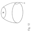
- FIGS. 11 and 12 show, as a variant, different mirror optics 17.
- a substantially plate-shaped transparent body with schematically defractive structures such as, for example, is used to influence the exiting light. Prisms, truncated pyramids or totally reflective cavities with optionally partially reflective surface coatings used.
- the refractive structures 21 have the advantage that they can be made flat and small and have hardly any absorption losses. The light portions reflected back into the cavity emerge from the cavity again after being reflected several times at the various internal surfaces.
- optical diffraction structures 14 consists of a substantially plate-shaped body with schematically drawn optical diffraction structures. These structures are known as holographic optical elements or defractive optical elements or as computer-generated diffraction structures as so-called “kinoforms" or "binary optics".
- the defractive structures have the same advantages as refractive structures 21. In addition, they can be duplicated and manufactured very inexpensively.
Landscapes
- Engineering & Computer Science (AREA)
- General Engineering & Computer Science (AREA)
- Life Sciences & Earth Sciences (AREA)
- Sustainable Development (AREA)
- Non-Portable Lighting Devices Or Systems Thereof (AREA)
- Optical Fibers, Optical Fiber Cores, And Optical Fiber Bundles (AREA)
- Light Guides In General And Applications Therefor (AREA)
- Vessels And Coating Films For Discharge Lamps (AREA)
Abstract
Description
Die vorliegende Erfindung betrifft einen Leuchtkörper zur Beleuchtung von Räumen mit einem von einer Wandung begrenzten Hohlkörper, der zur Mehrfachreflexion von Licht im Inneren mit reflektierenden Innenflächen versehen ist, wobei die Innenflächen des Hohlkörpers einen Reflexionsgrad von mindestens 90 % aufweisen und lichtstreuend ausgebildet sind und in der Wandung des Hohlkörpers mindestens eine die Wandung durchbrechende Lichtaustrittsöffnung vorgesehen ist.The present invention relates to a luminous element for illuminating rooms with a hollow body bounded by a wall, which is provided for multiple reflection of light inside with reflective inner surfaces, wherein the inner surfaces of the hollow body have a reflectance of at least 90% and are designed to be light scattering and in the Wall of the hollow body is provided at least one wall which passes through the light exit opening.
Leuchtkörper zur Beleuchtung von Räumen sind beim Stand der Technik in einer großen Vielfalt und mit unterschiedlichsten Ausprägungen bekannt. Die verschiedenen Ausprägungen von Leuchtkörpern richten sich nach der Art ihrer Verwendung. Hier kann man generell zwischen Leuchtkörpern unterscheiden, welche dem punktuellen Beleuchten einer bestimmten Fläche dienen. Für diese Gattung von Leuchten sind als Beispiel eine Leselampe oder ein Spotlicht für die Ausleuchtung von Bühnen in Theatern oder dergleichen anzuführen. Eine andere Gattung von Leuchtkörpern dient der möglichst gleichmäßigen Ausleuchtung von Räumlichkeiten. Für diesen Zweck werden oft Deckenfluter, Anordnung von Leuchtstoffröhren usw. angewendet. Die Aufgabenstellung der punktuellen Ausleuchtung von bestimmten begrenzten Flächen wie auch die der gleichmäßigen Ausleuchtung von Räumen tritt oft gleichzeitig in geschlossenen Räumen auf. Beim Stand der Technik müssen häufig zur Lösung dieser Aufgabenstellungen verschiedenartige Leuchtkörper in Kombination eingesetzt werden. Oftmals wird die gesetzte Aufgabenstellung jedoch auch durch die Kombination von verschiedenartigen Leuchten nicht vollständig gelöst. Häufige Probleme sind des weiteren, daß bei verschiedenen Leuchtentypen unerwünschte Farbeffekte durch ein eingeschränktes Spektrum des ausgesandten Lichts hervorgerufen werden. So gibt z.B. eine Quecksilberdampflampe durch den in der Lichtquelle unten vorhandenen "Quecksilbersumpf" hindurch nach unten braunes Licht ab, während der Anteil des abgestrahlten Lichts, welches nicht den Sumpf durchdringen muß, eine blaue Färbung hat. Des weiteren werden Personen in den auszuleuchtenden Räumen teilweise durch die beim Stand der Technik verwendeten Leuchtkörper geblendet. Durch die Lampenbauform (Fassung, Sockel, Quetschung...) wie auch die Eigenschaften der verwendeten Lichtquellen wird bei gängigen Leuchtkörpern nach dem Stand der Technik in unterschiedliche Raumrichtungen unterschiedlich viel Licht (Intensität) abgestrahlt, wodurch mit gängigen Reflektoren eine gleichmäßige Verteilung kaum erreicht werden kann. Anders herum ist durch die gegebene Aufgabenstellung einer spezifischen Leuchte oft die äußere Form der Leuchte weitgehend vorgegeben, was eine starke Einschränkung beim Design einer Leuchte bedeutet.Luminaires for the illumination of rooms are known in the prior art in a wide variety and with various forms. The different forms of luminaires depend on the way they are used. Here you can generally distinguish between luminaires, which serve the selective illumination of a particular area. For this type of luminaires are as an example a reading lamp or a spotlight for the illumination of theaters in theaters or the like to cite. Another type of luminaires serves the most uniform possible illumination of premises. For this purpose, ceiling lights, arrangement of fluorescent tubes, etc. are often used. The task of the selective illumination of certain limited areas as well as the uniform illumination of rooms often occurs simultaneously in closed rooms. In the prior art, various types of luminous bodies often have to be used in combination to solve these problems. Often, however, the set task is not completely solved by the combination of different types of lights. Frequent problems are further that in different types of luminous unwanted color effects caused by a limited spectrum of the emitted light. For example, a mercury-vapor lamp emits brown light down through the "mercury sump" present in the light source below, while the proportion of radiated light which does not have to penetrate the sump has a blue coloration. Furthermore, persons in the spaces to be illuminated are partially blinded by the luminous bodies used in the prior art. Due to the lamp design (socket, base, pinch ...) as well as the properties of the light sources used is in common luminaires according to the prior art in different spatial directions different levels of light (intensity) radiated, whereby with common reflectors a uniform distribution can hardly be achieved. On the other hand, given the specific task of a specific luminaire, the outer shape of the luminaire is often largely predetermined, which means that there is a major limitation in the design of a luminaire.
Aus den Schriften DE 4 439 507 A1 und US 4,459,642 A sind Leuchtkörper mit Hohlkörpern bekannt, bei denen die Hohlkörper reflektierende Innenflächen aufweisen. In die in diesen Schriften gezeigten Leuchtkörper wird sowohl Sonnenlicht als auch künstliches Licht eingestrahlt. In dem Hohlkörper findet eine Nivellierung oder Mischung des von den verschiedenen Lichtquellen eingestrahlten Lichtes statt. Diese Nivellierung basiert auf einer Vielfachreflexion des in den Hohlkörper eingestrahlten Lichtes, an dessen reflektierenden Innenflächen. Die Lichtabgabe aus dem Leuchtkörper erfolgt bei der US 4,459,642 A über semi-transparente Bereiche in der Wandung des Hohlkörpers und in der DE 4 439 507 A1 über sogenannte Lichtaustrittssysteme, in denen das Licht ebenfalls über semi-transparente Bereiche austreten kann. Alle in diesen Schriften gezeigten Leuchtkörper haben den Nachteil, daß sie zwar zur gleichmäßigen und ausreichend hellen Raumausleuchtung nicht aber zur gezielten Beleuchtung begrenzter Teilräume mit erhöhtem Lichtbedarf wie z.B. zur Ausleuchtung von Arbeitsplätzen verwendet werden können. Hierzu reicht bei den beim Stand der Technik bekannten, oben genannten Leuchtkörpern die in den jeweiligen Hohlkörpern erzeugte Leuchtdichte nicht aus.The
Die GB 2340215 A offenbart einen gattungsgemäßen Leuchtkörper zur Beleuchtung von Räumen mit einem von einer Wandung begrenzten Hohlkörper, der zur Mehrfachreflexion von Licht im Inneren mit reflektierenden Innenflächen versehen ist, wobei die Innenflächen des Hohlkörpers einen Reflexionsgrad von mindestens 90 % aufweisen und lichtstreuend ausgebildet sind und in der Wandung des Hohlkörpers mindestens eine die Wandung durchbrechende Lichtaustrittsöffnung vorgesehen ist.GB 2340215 A discloses a generic luminous element for illuminating rooms with a hollow body bounded by a wall, which is provided for multiple reflection of light inside with reflective inner surfaces, wherein the inner surfaces of the hollow body have a reflectance of at least 90% and are designed to light scattering and in the wall of the hollow body at least one wall which passes through the light exit opening is provided.
Aufgabe der Erfindung ist es, die Effektivität der gattungsgemäßen Leuchtkörper weiter zu verbessern.The object of the invention is to further improve the effectiveness of the generic luminous body.
Dies wird erfindungsgemäß dadurch erreicht, daß sich aus der Innenfläche A0 der Wandung des Hohlkörpers, der Summe A1 aller Flächen aller Öffnungen in der Wandung und aus dem Reflexionsgrad Rho bei der Berechnung des Wirkungsgrades Eta nach der Formel Eta = Rho x f (1 - Rho (1 - f)) ein Wirkungsgrad Eta von mindestens 40 %, vorzugsweise von mindestens 65 %, ergibt, wobei f = A1 /(A1 + A0) ist und daß das Verhältnis der Innenfläche der Wandung des Hohlkörpers zur Summe aller Flächen aller Öffnungen, vorzugsweise aller Lichtaustrittsöffnungen, in der Wandung des Hohlkörpers größer als 5:1, vorzugsweise größer als 10:1, ist.This is inventively achieved in that from the inner surface A0 of the wall of the hollow body, the sum A1 of all surfaces of all openings in the Wall and from the reflectance Rho in the calculation of the efficiency Eta according to the formula Eta = Rho xf (1 - Rho (1 - f)) results in an efficiency Eta of at least 40%, preferably of at least 65%, where f = A1 / (A1 + A0) and that the ratio of the inner surface of the wall of the hollow body to the sum of all surfaces of all openings, preferably all light exit openings in the wall of the hollow body is greater than 5: 1, preferably greater than 10: 1, is.
Auch bei der Erfindung ist es somit vorgesehen, daß der Leuchtkörper eine die Wandung des Hohlkörpers durchbrechende Lichtaustrittsöffnung aufweist. Diese gezielte Lichtauskopplung kann zur konzentrierten Beleuchtung von begrenzten Flächen, aber auch zur gezielten Ausleuchtung von Räumen verwendet werden. Hierbei wird insgesamt eine deutlich verbesserte Ausleuchtung als mit den beim Stand der Technik bekannten Hohlkörperleuchten erreicht. Die Anwendung von Lichtaustrittsöffnungen ist erst durch eine ausreichend hohe Leuchtdichte im Inneren des Leuchtkörpers möglich. Die hohe Leuchtdichte und damit ein wirtschaftlicher Betrieb solcher Leuchten mit einem entsprechenden hohen Leuchtenbetriebswirkungsgrad ist erst durch den erfindungsgemäßen Reflexionsgrad der Innenflächen des Hohlkörpers von mindestens 90 % möglich. Durch die lichtstreuende Ausbildung der Innenflächen des Hohlkörpers wird darüber hinaus zum einen erreicht, daß Lichtquellen oder andere Bauteile innerhalb des Hohlkörpers nicht nach außen abgebildet werden. Zum anderen resultiert die lichtstreuende Wirkung der Innenflächen darin, daß vom Leuchtkörper nur angenehm diffus gestreutes Licht abgestrahlt wird. Unter lichtstreuend wird hierbei nicht nur eine vollkommen richtungsunabhängige ideale Streuung sondern im allgemeinen eine Aufweitung des reflektierten Lichtstrahls bezeichnet. Insgesamt ist die erfindungsgemäße lichtstreuende Wirkung dadurch charakterisiert, daß das den Leuchtkörper verlassende Licht keine Vorzugsrichtungen mehr aufweist. Dies kann, wie weiter unten angeführt, durch verschiedene Maßnahmen erreicht werden.Also in the invention, it is thus provided that the luminous body has a wall of the hollow body which passes through the light exit opening. This targeted light extraction can be used for concentrated illumination of limited areas, but also for the targeted illumination of rooms. In this case, overall a significantly improved illumination is achieved than with the known in the prior art hollow body lamps. The use of light exit openings is possible only by a sufficiently high luminance in the interior of the luminous element. The high luminance and thus an economical operation of such lamps with a corresponding high luminaire efficiency is only possible by the inventive reflectance of the inner surfaces of the hollow body of at least 90%. Due to the light-scattering design of the inner surfaces of the hollow body is also achieved on the one hand, that light sources or other components within the hollow body are not displayed to the outside. On the other hand, the light-scattering effect of the inner surfaces results in that only diffusely diffused light is radiated from the luminous body. Under light scattering not only a perfect direction independent ideal scattering but in general an expansion of the reflected light beam is called. Overall, the light-scattering effect according to the invention is characterized in that the light leaving the luminous element no longer has preferred directions. This can, as stated below, be achieved by various measures.
Die Leuchtdichte in einem Hohlkörper mit einer weitgehend geschlossenen Innenfläche steigt mit wachsendem Reflexionsgrad von einer Leuchtdichte = 0 bei einem Reflexionsgrad = 0 % theoretisch bis zu einer unendlich großen Leuchtdichte bei einem Reflexionsgrad der Innenflächen von 100 % an. Daher weisen die Innenflächen des Hohlkörpers in bevorzugten Ausführungsformen einen Reflexionsgrad größer als 95 % bzw. 97 % oder größer als 98 % bzw. 99 % auf. Hierbei gilt, daß der oben geschilderte erfindungsgemäße Effekt umso besser ausgenützt werden kann je näher der Reflexionsgrad der Innenfläche des Hohlkörpers sich den 100 % nähert.The luminance in a hollow body with a largely closed inner surface increases with increasing reflectance from a luminance = 0 at a reflectance = 0% theoretically up to an infinitely large luminance with a reflectance of the inner surfaces of 100%. Therefore, in preferred embodiments, the inner surfaces of the hollow body have a reflectance greater than 95% and 97% or greater than 98% and 99%, respectively. It is true that the above described effect can be better utilized the closer the reflectance of the inner surface of the hollow body approaches 100%.
Da alle Öffnungen im Hohlkörper des Leuchtkörpers nicht oder nur gering reflektierende Flächen sind, wird der effektive Reflexionsgrad der Innenflächen durch sie vermindert. Dies führt zu einer Verminderung der Leuchtdichte im Inneren des Leuchtkörpers bzw. des Hohlkörpers. Daher ist es erfindungsgemäß vorgesehen, daß das Verhältnis der Innenfläche der Wandung des Hohlkörpers zur Summe aller Flächen aller Öffnungen, vorzugsweise aller Lichtaustrittsöffnungen, in der Wandung des Hohlkörpers größer als 5:1, vorzugsweise größer als 10:1, ist. Je nach Aufgabenstellung des Leuchtkörpers ist günstigerweise auch ein Verhältnis der Fläche der Wandung des Hohlkörpers zur Summe aller Flächen aller Öffnungen in der Wandung des Hohlkörpers größer als 20 : 1 bzw. größer als 30 : 1 oder vorzugsweise sogar größer als 40 : 1 anzustreben.Since all openings in the hollow body of the luminous are not or only slightly reflective surfaces, the effective reflectance of the inner surfaces is reduced by them. This leads to a reduction in the luminance in the interior of the luminous body or of the hollow body. Therefore, it is provided according to the invention that the ratio of the inner surface of the wall of the hollow body to the sum of all surfaces of all openings, preferably all light exit openings in the wall of the hollow body is greater than 5: 1, preferably greater than 10: 1, is. Depending on the task of the filament is also a ratio of the surface of the wall of the hollow body to the sum of all surfaces of all openings in the wall of the hollow body greater than 20: 1 or greater than 30: 1 or preferably even greater than 40: 1 strive.
Insgesamt ist ein Leuchtkörper nur dann sinnvoll betreibbar, wenn sein Wirkungsgrad Eta oberhalb eines gewissen Mindestwertes liegt. Hierbei hängt der Wirkungsgrad Eta von der Innenfläche der Wandung der Summe aller Flächen aller Öffnungen und vom Reflexionsgrad der Innenflächen ab. Gemäß der Erfindung ist daher vorgesehen, daß sich aus der Innenfläche A0 der Wandung des Hohlkörpers, der Summe A1 aller Flächen aller Öffnungen in der Wandung und aus dem Reflexionsgrad Rho bei der Berechnung des Wirkungsgrades Eta nach der Formel 
ein Wirkungsgrad Eta von mindestens 40 %, vorzugsweise von mindestens 65 %, ergibt, wobei f = A1 / (A1 + A0) ist. Der Wirkungsgrad Eta ist hierbei im allgemeinen als Verhältnis des Lichtstroms, welcher durch A1 aus dem Hohlkörper austritt zu dem Lichtstrom der speisenden Lichtquellen definiert. Praktischerweise ist in vielen Ausführungsformen von Leuchtkörpern vorzusehen, daß die Fläche der Lichtaustrittsöffnung(en) möglichst klein gehalten wird, da hierdurch eine weiterführende Lichtlenkung des durch die Lichtaustrittsöffnungen abgegebenen Lichtstroms durch eine entsprechende Optik vereinfacht ist. Dies ist z.B. der Fall, wenn weiterführende lichtlenkende Reflektoren verwendet werden sollen. Aus der oben angegebenen Formel für den Wirkungsgrad Eta ergibt sich z.B. daß, wenn ein Wirkungsgrad von 65 % mit den beim Stand der Technik bekannten guten Reflexionsgraden von ca. 85 % erreicht werden soll, das Flächenverhältnis f mehr als 32 % betragen müßte. Verwendet man jedoch einen hohen Reflexionsgrad von z.B. 95 % so ergibt sich für das Flächenverhältnis f ein Wert von 9,7 %, was wiederum bedeutet, daß die Fläche der Lichtaustrittsöffnungen dank des hohen Reflexionsgrades wesentlich kleiner gehalten werden kann, ohne daß Einbußen beim Wirkungsgrad in Kauf genommen werden müßten. Bei entsprechend höheren Reflexionsgraden können noch entsprechend kleinere Lichtaustrittsöffnungen bei gleichbleibendem Wirkungsgrad verwendet werden.Overall, a luminous element can only be operated effectively if its efficiency Eta is above a certain minimum value. In this case, the efficiency Eta depends on the inner surface of the wall of the sum of all surfaces of all openings and the reflectance of the inner surfaces. According to the invention it is therefore provided that from the inner surface A0 of the wall of the hollow body, the sum A1 of all surfaces of all openings in the wall and from the reflectance Rho in the calculation of the efficiency Eta according to the formula
gives an efficiency Eta of at least 40%, preferably of at least 65%, where f = A1 / (A1 + A0). In this case, the efficiency Eta is generally defined as the ratio of the luminous flux which exits the hollow body through A1 to the luminous flux of the feeding light sources. Conveniently, in many embodiments of luminous bodies, provision must be made for the area of the light exit opening (s) to be kept as small as possible, since this further simplifies the directing of the light flux emitted by the light exit openings through a corresponding optical system. This is the case, for example, if further light-directing reflectors are to be used. From the above formula for the efficiency Eta results, for example, that when a Efficiency of 65% with the known in the prior art good reflectance of about 85% should be achieved, the area ratio f should be more than 32%. However, using a high reflectance of, for example, 95%, the result for the area ratio f is a value of 9.7%, which in turn means that the surface of the light exit openings can be kept much smaller thanks to the high reflectance, without sacrificing the efficiency in Purchase would have to be taken. With correspondingly higher degrees of reflection, correspondingly smaller light exit openings can be used with constant efficiency.
Eine bevorzugte Ausführungsform des erfindungsgemäßen Leuchtkörpers sieht vor, daß im Leuchtkörper mindestens eine Lichteinlaßöffnung vorzugsweise zum Einlaß von Tageslicht und/oder Sonnenlicht und/oder mindestens eine künstliche Lichtquelle angeordnet ist. Der Hohlkörper mit diffus reflektierender Innenfläche kann auch ein oder mehrere Lichteintrittsöffnung(en) aufweisen, um alternativ oder zusätzlich zu einer integrierten Lichtquelle natürliches oder künstliches Licht von außen durch die Öffnungen in den Hohlkörper einzuspeisen. Durch die Vielfachreflexion des Lichts an den Innenflächen des Hohlkörpers ist die Lage der Lichteintrittsöffnung oder der künstlichen Lichtquelle im Hohlkörper des Leuchtkörpers unabhängig von der vom Leuchtkörper insgesamt abgestrahlten Leuchtwirkung. Dies ermöglicht eine sehr große Freiheit in der Gestaltung der Form des Leuchtkörpers. Darüber hinaus wird garantiert, daß die aus der Lichtaustrittsöffnung austretende Lichtverteilung stets diffus gestreut und unabhängig von der Lichtverteilung der im Hohlkörper befindlichen Lichtquelle und unabhängig von der Lichtverteilung der durch die Eintrittsöffnung einströmenden Lichtquelle ist. Wenn sowohl natürliches als auch künstliches Licht in den Hohlkörper eingestrahlt wird, so kann durch eine entsprechende Steuerung des Anteils an künstlichem Licht eine nahezu gleichmäßige Intensität des vom Leuchtkörper abgestrahlten Lichts bei maximal möglichem Sonnenlichtanteil über den gesamten Tagesablauf hinweg in Innenräumen aufrecht erhalten werden.A preferred embodiment of the filament according to the invention provides that in the luminous body at least one light inlet opening preferably to the inlet of daylight and / or sunlight and / or at least one artificial light source is arranged. The hollow body with a diffusely reflecting inner surface can also have one or more light entry opening (s) in order to feed natural or artificial light from outside through the openings into the hollow body as an alternative or in addition to an integrated light source. Due to the multiple reflection of the light on the inner surfaces of the hollow body, the position of the light entry opening or the artificial light source in the hollow body of the luminous element is independent of the overall luminous effect emitted by the luminous element. This allows a very great freedom in the design of the shape of the filament. In addition, it is guaranteed that the light distribution emerging from the light exit opening is always diffused and independent of the light distribution of the light source located in the hollow body and independent of the light distribution of the light source flowing through the inlet opening. If both natural and artificial light is irradiated into the hollow body, it can be maintained by a corresponding control of the proportion of artificial light, a nearly uniform intensity of the light emitted by the lamp with maximum sunlight proportion over the entire daily routine indoors.
Eine bevorzugte Ausführungsform sieht vor, daß im Leuchtkörper zwei oder mehrere Lichtquellen oder Lichteinlaßöffnungen, vorzugsweise zum Einlaß von Tageslicht und/oder Sonnenlicht angeordnet sind, wobei die Mehrfachreflexion an den hochreflektierenden Innenflächen das in den Hohlkörper eingebrachte Licht, vorzugsweise praktisch vollständig, mischt. So wird verschiedenfarbiges Licht, ob es nun von einer oder unterschiedlichen Lichtquellen in den Hohlkörper des Leuchtkörpers eingestrahlt wird, in der Weise durch Mehrfachreflexionen des Lichts an den Innenflächen des Hohlkörpers gemischt, daß es die Lichtaustrittsflächen stets als Mischlicht, vorzugsweise weißes Licht, verläßt. So kann Tageslicht mit Kunstlicht oder verschiedenfarbiges Licht von verschiedenen Lichtquellen im Hohlkörper des Leuchtkörpers gezielt gemischt werden.A preferred embodiment provides that two or more light sources or light inlet openings, preferably for the entrance of daylight and / or sunlight are arranged in the luminous body, wherein the multiple reflection at the highly reflective inner surfaces, the light introduced into the hollow body, preferably almost completely, mixes. Thus, differently colored light, whether it is irradiated by one or different light sources in the hollow body of the filament, mixed in the way by multiple reflections of the light on the inner surfaces of the hollow body, that it always leaves the light exit surfaces as a mixed light, preferably white light. Thus, daylight with artificial light or different colored light from different light sources in the hollow body of the luminous body can be mixed specifically.
Durch die Lichtmischwirkung des erfindungsgemäßen Leuchtkörpers kann dieser auch derart ausgebildet sein, daß mindestens eine Lichtquelle vorgesehen ist, die in unterschiedliche Raumrichtungen verschiedenfarbiges Licht mit unterschiedlicher Spektralverteilung abstrahlt, wobei die Mehrfachreflexion des Lichts an der hochreflektierenden Innenfläche des Hohlkörpers das Licht verschiedener spektraler Lichtverteilung bzw. Farbverteilung - vorzugsweise zu weißem Licht - mischt. Hierbei kann alternativ auch vorgesehen sein, daß zwei oder mehrere Lichtquellen vorgesehen sind, die Licht mit jeweils verschiedener spektraler Lichtverteilung bzw. verschiedenem Farbinhalt abstrahlen, wobei die Mehrfachreflexion des Lichts an der hochreflektierenden Innenfläche des Hohlkörpers das Licht verschiedener spektraler Verteilung - vorzugsweise zu weißem Licht - mischt.Due to the light mixing effect of the luminous body according to the invention this can also be designed such that at least one light source is provided which emits different colored light with different spectral distribution in different spatial directions, the multiple reflection of the light on the highly reflective inner surface of the hollow body, the light of different spectral Light distribution or color distribution - preferably to white light - mixes. This may alternatively be provided that two or more light sources are provided which emit light with different spectral light distribution or different color content, the multiple reflection of the light on the highly reflective inner surface of the hollow body, the light of different spectral distribution - preferably to white light - mixed.
Neben der Farbmischung kann eine erfindungsgemäße Ausführungsform des Leuchtkörpers auch dazu verwendet werden, die Richtungsabhängigkeit der Intensität des Lichts, welche durch die Abstrahlcharakteristik einer Lichtquelle hervorgerufen ist, zu beseitigen. So sieht eine bevorzugte Ausführungsform vor, daß mindestens eine Lichtquelle vorgesehen ist, die in verschiedene Raumrichtungen Licht mit unterschiedlicher Intensität abstrahlt, wobei die Mehrfachreflexion des Lichts an der hochreflektierenden Innenfläche des Hohlkörpers dazu führt, daß die Intensität des vom Leuchtkörper - vorzugsweise über mindestens eine Lichtaustrittsöffnung - abgegebenen Lichts vollständig richtungsunabhängig ist. Durch die (diffuse) Mehrfachreflexion an der Innenseite wird unabhängig von ihrer ursprünglichen Ausstrahlungscharakteristik jede Lichtquelle (paralleles Sonnenlicht, diffuses Leuchtstofflampenlicht, Glühlampenlicht etc.) in eine "diffus strahlende Flächenlichtquelle" umgewandelt, die - vorzugsweise mit Reflektoren - gut beherrschbar ist. Die durch die Mehrfachreflektion erreichte Nivellierung der Intensität, der Richtung und des Farbgehaltes des von der oder den Lichtquellen abgestrahlten Lichts ist im speziellen auch für die Verwendung von verschiedenfarbigen punkt- und linienförmigen Lichtquellen oder verschiedenfarbigen Hochdruckentladungslampen günstig. Darüber hinaus kann der Nivellierungseffekt auch bei der Verwendung von mehreren Halbleiterlichtquellen (z.B. LEDs) verwendet werden.In addition to color mixing, an inventive embodiment of the luminous element can also be used to eliminate the directional dependence of the intensity of the light, which is caused by the emission characteristic of a light source. Thus, a preferred embodiment provides that at least one light source is provided which emits light of different intensity in different spatial directions, wherein the multiple reflection of the light at the highly reflective inner surface of the hollow body leads to the fact that the intensity of the luminous body - preferably via at least one light exit opening - emitted light is completely independent of direction. Due to the (diffuse) multiple reflection on the inside of each light source (parallel sunlight, diffused fluorescent light, incandescent light, etc.) is converted into a "diffused surface light source" regardless of their original radiation characteristics, which - is easy to control - preferably with reflectors. The achieved by the multiple reflection leveling the intensity, the direction and the color content of the light emitted by the light source or sources is particularly favorable for the use of different-colored point and line light sources or different colored high-pressure discharge lamps. Moreover, the leveling effect can also be used with the use of multiple semiconductor light sources (e.g., LEDs).
Die erfindungsgemäßen hochreflektierenden Eigenschaften der Innenfläche des Hohlkörpers können, wie oben bereits angeführt, durch verschiedene Maßnahmen erreicht werden. So sieht eine bevorzugte Variante vor, daß die lichtstreuenden hochreflektierenden Innenflächen zumindest bereichsweise, vorzugsweise vollständig, eine lichtstreuende vorzugsweise weiße Folie aufweisen. Eine solche weiße Folie kann z.B. aus Polytetrafluoroethylen (PTFE) hergestellt werden. In einer anderen Ausführungsvariante kann alternativ dazu auch vorgesehen sein, daß die lichtstreuenden hochreflektierenden Innenflächen zumindest bereichsweise, vorzugsweise vollständig, eine lichtstreuende aufgerauhte, mattierte oder geätzte Oberfläche aufweisen.The highly reflective properties of the inner surface of the hollow body according to the invention can, as stated above, be achieved by various measures. Thus, a preferred variant provides that the light-scattering highly reflective inner surfaces at least partially, preferably completely, have a light-diffusing preferably white film. Such a white film can be made, for example, from polytetrafluoroethylene (PTFE). Alternatively, it can also be provided in another embodiment that the light-scattering highly reflecting inner surfaces at least partially, preferably completely, have a light-scattering roughened, frosted or etched surface.
Abweichend von diesen beiden Möglichkeiten kann darüber hinaus auch vorgesehen sein, daß die lichtstreuenden hochreflektierenden Innenflächen zumindest bereichsweise vorzugsweise vollständig eine - vorzugsweise aus Noppen, Vielfachkantung, Rillen oder anderen geraden oder schiefen Unebenheiten gebildetelichtstreuende makroskopische Oberflächenstruktur, aufweisen. Bei dieser Form der Ausbildung der hochreflektierenden lichtstreuenden Innenflächen kann sogar vorgesehen sein, daß die makroskopische Oberflächenstruktur aus glänzendem oder hochglänzendem Material besteht. Ein Beispiel für diese Variante besteht z.B. darin, eine hochglänzende Folie oder ein hochglänzendes Reflektorblech, dessen Oberfläche genoppt, gerillt, mehrfach gekantet oder dergleichen ausgeführt ist, zu verwenden. Auch auf diese Weise können Reflexionsgrade der Innenflächen des Hohlkörpers größer 95 % oder 98 % erzielt werden. Allen diese verschiedenen Varianten der Ausbildung der hochreflektierenden lichtstreuenden Innenflächen ist jedoch gemeinsam, daß das letztendlich den Leuchtkörper durch die Lichtaustrittsöffnung verlassende Licht angenehm diffus gestreut ist.Notwithstanding these two possibilities can also be provided beyond that the light-scattering highly reflective inner surfaces at least partially preferably a completely - preferably formed of knobs, Vielfachkantung, grooves or other straight or oblique irregularities formed light-scattering macroscopic surface structure. In this form of formation of the highly reflective light-scattering inner surfaces may even be provided that the macroscopic surface structure consists of glossy or high-gloss material. An example of this variant is e.g. It is to use a high-gloss film or a high-gloss reflector sheet, the surface of which is grooved, grooved, creased multiple or the like. In this way, reflectivities of the inner surfaces of the hollow body greater than 95% or 98% can be achieved. However, all these different variants of the design of the highly reflective light-scattering inner surfaces have in common that the light ultimately leaving the luminous body through the light exit opening is pleasantly diffused.
Eine besonders bevorzugte Ausführungsform sieht vor, daß mindestens eine lichtlenkende, vorzugsweise parabolisch geformte, Spiegeloptik oder eine andere Lichtlenkeinrichtung im Bereich der Lichtaustrittsöffnung des Leuchtkörpers angeordnet ist und das austretende Licht winkelmäßig begrenzt. Alternativ können auch Refraktoroptiken oder Diffraktoroptiken verwendet werden. Hierdurch wird zum einen bewirkt, daß das austretende Licht auf die zu beleuchtende Fläche bedarfsgerecht gezielt konzentriert wird. Andererseits wird verhindert, daß eine Person durch das aus dem Leuchtkörper austretende Licht geblendet wird. Zusätzlich können auch Blenden im Inneren des Hohlkörpers vorgesehen sein, wobei diese Blenden den direkten Blick auf die Lichtquelle oder die Lichteinlaßöffnung im Hohlkörper verhindern.A particularly preferred embodiment provides that at least one light-guiding, preferably parabolically shaped, mirror optics or another light-deflecting device is arranged in the region of the light exit opening of the luminous element and limits the exiting light angularly. Alternatively, refractor optics or diffractor optics may also be used. As a result, on the one hand causes the exiting light is selectively focused as needed on the surface to be illuminated. On the other hand, it prevents a person from being blinded by the light emerging from the luminous element. In addition, diaphragms can also be provided in the interior of the hollow body, these diaphragms preventing the direct view of the light source or the light inlet opening in the hollow body.
Eine bevorzugte Ausführungsform des erfindungsgemäßen Leuchtkörpers sieht vor, daß er eine vorzugsweise diffus streuende, für den nicht reflektierten Lichtanteil im wesentlichen lichtdurchlässige Wandung aufweist. Hierdurch wird eine besonders gleichmäßige und angenehme Ausleuchtung eines Raumes erzeugt. Durch die durch den hohen Reflexionsgrad erzeugte, stark konzentrierte Leuchtdichte innerhalb des Hohlraumes des Leuchtkörpers reicht der sehr geringe nicht an der Innenfläche des Hohlkörpers reflektierte sondern durch die Wandung transmittierte diffus gestreute Lichtanteil für eine für das menschliche Auge angenehme gleichmäßige Beleuchtung eines Raumes aus. Durch die Transmission des nicht reflektierenden Restlichts durch die Wandung wird somit der Wirkungsgrad des Leuchtkörpers weiter erhöht, da nahezu das gesamte wie auch immer eingespeiste Licht als Nutzlicht den Leuchtkörper verläßt.A preferred embodiment of the luminous body according to the invention provides that it has a preferably diffusely scattering, for the non-reflected light component substantially translucent wall. This creates a particularly uniform and pleasant illumination of a room. Due to the high reflectance generated, highly concentrated luminance within the Cavity of the filament extends from the very small not reflected on the inner surface of the hollow body but transmitted through the wall diffusely scattered light component for a pleasant for the human eye uniform illumination of a room. As a result of the transmission of the non-reflecting residual light through the wall, the efficiency of the luminous element is further increased since almost the entire light, which is also always fed in, leaves the luminous element as useful light.
Zur Verhinderung eines unnötigen Aufheizens der Wandung bzw. des Leuchtkörpers ist es günstig, daß die Wandung bzw. der Leuchtkörper möglichst wenig Lichtenergie in Form von Wärme absorbiert. Dies gilt vor allem für die außerhalb des sichtbaren Bereichs liegenden Spektralbereiche des Lichts, insbesondere für den infraroten Wellenlängenbereich. Erreicht werden kann die geringe Wärmeabsorption durch einen hohen Transmissionsgrad. Hierbei steht vor allem eine gute Transmission der infraroten Wellenlängenbereiche des Lichts im Vordergrund. So ist die Verwendung von Innenflächen mit einem Reflexionsgrad von mindestens 90 % für sichtbare Lichtanteile und einem Reflexionsgrad von nur ca. 20 % für den Infrarotbereich besonders günstig. Alternativ können aber auch Kühlrippen oder dergleichen am Hohlkörper vorgesehen sein. Zur Verhinderung von Verbrennungen sieht eine weitere Variante einen thermischen Berührungsschutz z.B. in Form von Gitter, Kunststoffrippen oder dergleichen vor.To prevent unnecessary heating of the wall or the luminous body, it is favorable that the wall or the luminous body absorbs as little light energy in the form of heat. This applies above all to the spectral regions of the light lying outside the visible range, in particular for the infrared wavelength range. The low heat absorption can be achieved by a high degree of transmittance. Above all, a good transmission of the infrared wavelength ranges of the light is in the foreground. Thus, the use of inner surfaces with a reflectance of at least 90% for visible light components and a reflectance of only about 20% for the infrared range is particularly favorable. Alternatively, however, cooling fins or the like may be provided on the hollow body. To prevent burns, another variant provides thermal shock protection e.g. in the form of mesh, plastic ribs or the like.
Soll die Oberfläche A0 des Hohlkörpers möglichst klein gehalten werden, ist um eine unzulässige Aufheizung des Hohlkörpers zu verhindern, darauf zu achten, daß der Wärmedurchgangskoeffizient k der Wandung des Hohlkörpers ausreichend groß ist. Durch die Gleichung A0 = P/(dT * k) kann für eine gegebene Lampenleistung P und eine maximal zulässige Temperaturerhöhrung dT der mindestens benötigte Wärmedurchgangskoeffizient k des für die Wandung verwendeten Materials berechnet werden.If the surface A0 of the hollow body is to be kept as small as possible in order to prevent unacceptable heating of the hollow body, it must be ensured that the heat transfer coefficient k of the wall of the hollow body is sufficiently large. By the equation A0 = P / (dT * k), for a given lamp power P and a maximum allowable temperature increase dT, the minimum required heat transfer coefficient k of the material used for the wall can be calculated.
Eine bevorzugte Ausführungsform sieht vor, daß der Leuchtkörper ein vorzugsweise quaderförmiger Hohlkörper ist, welcher mit einer hochreflektierenden Folie ausgekleidet ist, wobei in dem Hohlkörper mindestens eine Lampe oder mindestens eine Lichteintrittsöffnung, - vorzugsweise für Tageslicht und/oder Sonnenlicht - und mindestens eine Blende angeordnet ist, wobei der Direktstrahlungsanteil ausgeblendet ist. Hierdurch wird eine Blendung von Personen bei ansonsten sehr angenehmer gezielter Lichtverteilung verhindert.A preferred embodiment provides that the luminous element is a preferably cuboidal hollow body, which is lined with a highly reflective film, wherein in the hollow body at least one lamp or at least one light inlet opening, - preferably for daylight and / or sunlight - and at least one aperture is arranged , wherein the direct radiation component hidden is. As a result, glare is prevented from persons with otherwise very pleasant targeted light distribution.
Weitere Merkmale und Einzelheiten der vorliegenden Erfindung ergeben sich aus der nachfolgenden Figurenbeschreibung. Dabei zeigen
- Fig. 1
bis 3 - eine schematische Darstellung einer Glühlampe bzw. von Leuchtkörpern nach dem Stand der Technik,
- Fig. 4
bis 10 - verschiedene erfindungsgemäße Ausführungsformen eines Leuchtkörpers,
- Fig. 11
bis 14 - verschiedene Ausführungsvarianten von Spiegeloptiken, Refraktoroptiken und Diffraktoroptiken.
- Fig. 1 to 3
- a schematic representation of an incandescent lamp or of luminous bodies according to the prior art,
- Fig. 4 to 10
- various embodiments of a filament according to the invention,
- Fig. 11 to 14
- various embodiments of mirror optics, refractor optics and diffractor optics.
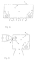
An den schematischen Darstellungen in Fig. 1 bis 3 werden die Nachteile von zahlreichen beim Stand der Technik bekannten Beleuchtungskörpern gezeigt. Fig. 1 zeigt eine einfache Glühlampe, bei der in Richtung der Fassung der Glühlampe kein Licht ausgestrahlt wird. Dies ist ein schematisches Beispiel dafür, daß Lichtquellen in der Regel eine Richtungsabhängigkeit in der abgestrahlten Intensität des Lichts aufweisen. In Fig. 2 wird dies anhand einer in einem Leuchtkörper 2 befindlichen Lichtquelle 1 verdeutlicht. Die Lichtquelle 1 in Fig. 2 strahlt in verschiedenen Richtungen Licht mit verschiedener Intensität ab. Dies resultiert letztendlich darin, daß im Winkelbereich senkrecht unter der Lichtquelle 1 bzw. der Lichtaustrittsöffnung 3 des Leuchtkörpers 2 Licht mit einer verhältnismäßig hohen Intensität abgestrahlt wird. Dies wird schematisch durch den Lichtstrahl 4 verdeutlicht. Im Gegensatz dazu nimmt die Intensität des abgestrahlten Lichts mit größer werdendem Winkel gegen die durch Strahl 4 verdeutlichte vertikale Abstrahlrichtung ab. Dadurch wird die Lichtintensität zu den Seiten hin geringer. Dieses seitlich abgestrahlte Licht geringerer Intensität wird durch die Strahlen 5 und 6 exemplarisch dargestellt.The drawbacks of numerous lighting fixtures known in the prior art are shown in the schematic illustrations in FIGS. 1 to 3. Fig. 1 shows a simple incandescent lamp in which no light is emitted in the direction of the socket of the incandescent lamp. This is a schematic example of the fact that light sources typically have a directionality in the radiated intensity of the light. In Fig. 2, this is illustrated by means of a
Neben dem Problem der Richtungsabhängigkeit der Intensität des abgestrahlten Lichts bei Leuchtkörpern gemäß dem Stand der Technik existiert beim Stand der Technik bei verschiedenen Lichtquellen auch das Problem, daß eine Richtungsabhängigkeit in der spektralen Verteilung des abgestrahlten Lichts besteht. Dies wird in Fig. 3 anhand einer schematischen Darstellung eines Leuchtkörpers mit einer Entladungslampe gezeigt. In einer Entladungslampe 8 bildet sich am Boden ein Lampensumpf 9. Dieser verändert den spektralen Gehalt (die Farbe) des durch ihn hindurchtretenden Lichts. So wird das von der Gasentladungslampe erzeugte Licht beim Durchtritt durch den Lampensumpf 9 derart gefiltert, daß es als braunes Licht die Gasentladungslampe nach unten hin verläßt. Ein solcher Lichtstrahl mit braunem Licht ist schematisch als Strahl 10 in Fig. 3 dargestellt. Im Gegensatz hierzu führt der Strahlenweg 11 nicht durch den Lampensumpf und das auf seinem Weg verlaufende Licht wird somit nicht durch den Lampensumpf gefiltert. Es verläßt auf seinem Weg über eine Reflexion am Reflektor 7 die Gasentladungslampe als blaues Licht. Die Gesamtlichtwirkung eines solchen Leuchtkörpers wird somit dadurch charakterisiert, daß auf der Nutzebene 12 störende Farbflecken existieren, da die Nutzebene 12 bereichsweise mit verschiedenfarbigem Licht ausgeleuchtet wird. Diese hier erläuterten Probleme bisheriger Beleuchtungstechnik können auch nicht durch die beim Stand der Technik bekannte Hohlkörperleuchten ausreichend gelöst werden, da diese nicht zur gezielten Beleuchtung abgegrenzter Bereiche (z.B. von Arbeitsplätzen) verwendet werden können.In addition to the problem of the directional dependence of the intensity of the radiated light in prior art luminaires, there is also the problem in the prior art of different light sources that there is a directionality in the spectral distribution of the radiated light. This is shown in FIG. 3 on the basis of a schematic representation of a luminous body with a discharge lamp. In a discharge lamp 8 forms at the bottom of a
Fig. 4 zeigt nun eine erfindungsgemäße Ausführungsform eines Leuchtkörpers. Das von der Lichtquelle 13 abgestrahlte Licht wird an der lichtstreuend hochreflektierend ausgebildeten Innenfläche 14 des Hohlkörpers 15 mehrfach reflektiert, bevor ein Teil des Lichts durch die Lichtaustrittsöffnung 16 den Leuchtkörper verläßt. Die lichtstreuend hochreflektierenden Eigenschaften der Innenflächen 14 können in allen Ausführungsbeispielen z.B. durch geeignete Anstriche, makroskopische Oberflächenstrukturen oder das Einkleben von geeigneten Folien erreicht werden. Solche Folien können z.B. aus Polytetraethylenfolien oder aus mehrschichtigen polymerischen Filmen mit einer Außenschicht aus Polyethylenenaphthalate (PEN) gebildet werden.4 now shows an embodiment according to the invention of a luminous element. The light emitted by the
An der Lichtaustrittsöffnung 16 kann je nach Bedarf eine Spiegeloptik 17 oder eine sonstige lichtlenkende Einrichtung (vgl. Fig. 11 bis 14) angebracht werden. Hierbei ist vorgesehen, daß unterschiedlichste Spiegelrasteroptiken an die Lichtaustrittsöffnung angebracht werden und damit eine Vielzahl von verschiedenen an den jeweiligen Bedarf angepaßten Lichtwirkungen erzielt werden können. Die Blende 18 verhindert, daß Licht auf direktem Wege von der Lampe 13 durch die Lichtaustrittsöffnung 16 den Leuchtkörper verlassen kann. Hierdurch wird verhindert, daß eine Person durch direkt von der Lichtquelle abgestrahltes Licht geblendet wird. Das durch die Lichtaustrittsöffnung 16 den Leuchtkörper verlassende Licht ist vor dem Verlassen des Leuchtkörpers mehrfach an der hochreflektierenden Innenfläche 14 lichtstreuend reflektiert worden und ist somit ein vollkommen richtungsunabhängiges, spektral vollständig gemischtes, angenehmes diffuses Licht. Zusätzlich zur Beleuchtung des Raumes über die Lichtaustrittsöffnung 16 kann vom Leuchtkörper auch diffuses Licht durch die Wandung des Hohlkörpers 15 abgegeben werden, wenn die Wandung des Hohlkörpers 15 lichtdurchlässig ausgebildet ist. Hierbei ist zu berücksichtigen, daß trotz des hohen Reflexionsgrades der Innenfläche 14 des Hohlkörpers 15 eine für die Beleuchtung eines Raumes ausreichende Lichtmenge durch die hochreflektierende Innenfläche und die Wandung des Hohlkörpers 15 transmittiert werden kann, da zum einen bei geeigneter Wandung deren Absorption zu vernachlässigen ist und zum anderen durch die Mehrfachreflexion eine derart hohe Leuchtdichte im Innenraum 19 des Hohlkörpers erzeugt wird, daß der geringe prozentuale Anteil des transmittierten Restlichts immer noch zur angenehmen Beleuchtung von Räumen ausreicht. Das Verhältnis zwischen dem durch die Wandung 15 des Leuchtkörpers austretenden Lichts und der Menge des durch die Lichtaustrittsöffnung 16 austretenden Lichts wird im wesentlichen durch das Verhältnis aus der Fläche der Lichtaustrittsöffnung 16 und der Gesamtfläche der hochreflektierenden Innenwandung 14 des Hohlkörpers 15 bestimmt und kann an den jeweiligen Bedarf angepaßt werden. Es ist somit eine genaue Steuerung zwischen den Anteilen der allgemeinen Raumbeleuchtung mit angenehm diffusen Licht und der konzentrierten Ausleuchtung von begrenzten Flächen möglich.At the
Durch eine entsprechende Ausführung des erfindungsgemäßen Leuchtkörpers kann für Büroarbeitsplätze eine Blendungsbegrenzung in alle Raumrichtungen für Winkelbereiche über 65° auf die Vertikale auf weniger als 1000 cd/m2 erreicht werden.By a corresponding embodiment of the filament according to the invention, a glare limitation in all spatial directions for angular ranges above 65 ° to the vertical to less than 1000 cd / m 2 can be achieved for office workplaces.
Fig. 5 zeigt eine Variante mit zwei Lichtquellen 13, bei der der Hohlkörper 15 eine insgesamt ovale Querschnittsform und eine in die Wandung integrierte Spiegelrasteroptik 17 aufweist. Fig. 6 zeigt schematisch eine Variante mit mehreren Lichtaustrittsöffnungen 16.5 shows a variant with two
Fig. 7 zeigt eine erfindungsgemäße Ausführungsform, bei der paralleles Sonnenlicht durch eine Lichteintrittsöffnung 20 in den Innenraum 19 des Hohlkörpers 15 eintritt. Durch Mehrfachreflexion des eintretenden Lichts an der hochreflektierend ausgebildeten Innenfläche 14 des Hohlkörpers 15 wird das eintretende Sonnenlicht in ein vollkommen richtungsunabhängiges diffuses Licht verwandelt und tritt anschließend aus der Lichtaustrittsöffnung 16 aus. Zusätzlich kann wiederum die Wandung 15 des Hohlkörpers lichtdurchlässig ausgebildet sein, wodurch auch ein Teil des Lichts durch die Wandung 15 des Leuchtkörpers transportiert und als diffus gestreutes Licht abgegeben wird. An die Lichtaustrittsöffnung 16 kann wie bei der Ausführungsform in Fig. 4 auch eine an den jeweiligen Bedarf angepaßte Spiegelrasteroptik 17 angebracht werden. Die Blende 18 verhindert wiederum, daß das durch die Lichteintrittsöffnung 20 eintretende Sonnenlicht direkt den Leuchtkörper durch die Lichtaustrittsöffnung 16 wieder verläßt, bevor es an den Innenwänden 14 mehrfach reflektiert wird.FIG. 7 shows an embodiment according to the invention in which parallel sunlight enters the interior 19 of the
Der Transport von Sonnenlicht zum Leuchtkörper kann, wie beim Stand der Technik bekannt, in einem Kanal aus vollreflektierenden Prismen oder in Lichtwellenleitern erfolgen. Als Alternative sind auch hochreflektierende Spiegelmaterialien möglich. Generell können als System zum Auffangen, Bündeln und Transportieren des Sonnenlichts bis zu dem zu beleuchtenden Raum Vorrichtungen nach dem Stand der Technik verwendet werden. Eine bevorzugte Ausführungsform hierzu sieht vor, daß der Leuchtkörper über eine Lichtleitung mit einem Heliostaten optisch verbunden ist, welcher das Sonnenlicht über die Lichtleitung in den Leuchtkörper leitet. Der Heliostat besteht dabei gemäß dem Stand der Technik im wesentlichen aus einer Anordnung von Spiegeln, deren Ausrichtung dem Lauf der Sonne nachgesteuert wird, sodaß solange wie möglich die optimale Menge Licht in die Lichtleitung eingekoppelt wird.The transport of sunlight to the luminous element can, as known in the prior art, take place in a channel made of fully reflecting prisms or in optical waveguides. As an alternative, highly reflective mirror materials are also possible. In general, prior art devices may be used as the system for collecting, bundling and transporting the sunlight to the room to be illuminated. A preferred embodiment for this purpose provides that the luminous element is optically connected via a light pipe to a heliostat which directs the sunlight into the luminous body via the light pipe. The heliostat according to the prior art consists essentially of an array of mirrors whose orientation is tracked the course of the sun, so that as long as possible the optimum amount of light is coupled into the light pipe.
Zusätzlich zur Lichteintrittsöffnung 20, durch welche Sonnenlicht oder das Licht von externen künstlichen Lichtquellen eingebracht wird, kann noch eine zusätzliche künstliche Lichtquelle 13 angebracht ist. Diese Kombination aus mindestens einer Lichteintrittsöffnung und mindestens einer zusätzlichen Lichtquelle soll schematisch die Vielzahl der Kombinationsmöglichkeiten zwischen Kunst- und natürlichem Licht oder verschiedenen künstlichen Lichtquellen mit verschiedenen Abstrahlcharakteristiken und abgestrahlten Strahlenverteilungen des Lichts verdeutlichen.In addition to the light entry opening 20 through which sunlight or the light from external artificial light sources is introduced, an additional artificial
In Fig. 8 wird noch einmal eine Variante zur Ausnutzung der Mischwirkung der Mehrfachreflexion des eingestrahlten Lichts im erfindungsgemäßen Hohlkörper des Leuchtskörpers verdeutlicht. Hier ist exemplarisch eine Vielzahl von kleinen Lichtquellen (z.B. verschiedenfarbige LEDs) im Hohlkörper angeordnet.FIG. 8 once again illustrates a variant for utilizing the mixing effect of the multiple reflection of the incident light in the hollow body of the luminous body according to the invention. Here, by way of example, a multiplicity of small light sources (eg LEDs of different colors) are arranged in the hollow body.
Neben der Mischung zu weißem Mischlicht kann durch die Verwendung entsprechender Lichtquellen, welche Licht mit bevorzugter spektraler Verteilungen (Farben) abstrahlen, auch Licht mit einer besonderen Farbwirkung gezielt gemischt werden, falls dies benötigt wird.In addition to the mixture to white mixed light, by using appropriate light sources, which emit light with preferred spectral distributions (colors), also light with a special color effect can be deliberately mixed, if needed.
Fig. 9 zeigt eine Ausführungsvariante, bei der als Lichtquelle 13 eine Leuchtstoffröhre im Hohlkörper angeordnet ist .Fig. 10 zeigt schematisch eine Variante, bei der die lichtstreuende Wirkung der Innenflächen 14 des Hohlkörpers durch eine makroskopische Oberflächenstruktur erreicht wird. In dieser Variante können die Innenflächen sogar glänzend ausgeführt sein, da die lichtstreuende Wirkung durch die Oberflächenstruktur erreicht wird.FIG. 9 shows a variant embodiment in which a fluorescent tube is arranged in the hollow body as
Insgesamt ergibt sich durch die Verwendung der erfindungsgemäß hochreflektierenden Innenflächen des Hohlkörpers, daß das vom Hohlkörper letztendlich abgegebene Licht unabhängig von der tatsächlichen Form des Hohlkörpers und damit des Leuchtkörpers nahezu vollständig diffus gestreut und richtungsunabhängig ist. Dies bedeutet eine große Freiheit bei der Gestaltung des Leuchtkörpers, ohne daß seine Lichtwirkung negativ beeinflußt würde. Hierbei ist es im allgemeinen günstig, daß das Verhältnis zwischen der Oberfläche des Hohlkörpers und dem umschlossenen Volumen des Hohlkörpers nicht das zweifache dieses Verhältnisses bei einer Kugel mit demselben Volumen übersteigt. Als weitere Dimensionierungsrichtlinie kann ebenfalls berücksichtigt werden, daß die maximale diagonale Ausdehnung nicht größer als das Dreifache der minimalen Diagonalen Ausdehnung beträgt. Bei elypsoidförmigen oder kugelförmigen Hohlkörpern wird im allgemeinen ein besonders hoher Wirkungsgrad erreicht. Andere günstige Formen sind zusammengesetzt aus ebenen Oberflächensegmenten oder aus zylindrisch gerollten Oberflächensegmenten und/oder kegelförmig gerollten Oberflächensegmenten. Diese Formen sind vorteilhaft, da sie einfach aus einem Folienmaterial durch Rollen, Kanten und Zusammenfügen hergestellt werden können. Andere günstige Formen sind im wesentlichen konvexe Polyeder, wie z.B. reguläre Polyeder (Tetraeder Würfel, Oktaeder, Dekaeder und Ikosaeder) sowie verzerrte reguläre Polyeder (z.B. Quader und allgemeine Pyramiden). Diese Ausführungsformen haben den Vorteil, daß sie aus wenigen ebenen Obeflächensegmenten bestehen und somit ebenfalls einfach hergestellt werden können.Overall, results from the use of the invention highly reflective inner surfaces of the hollow body, that the final emitted from the hollow body light is scattered almost completely diffused regardless of the actual shape of the hollow body and thus the filament and direction independent. This means a great deal of freedom in the design of the filament without its light effect would be adversely affected. In this case, it is generally favorable that the ratio between the surface of the hollow body and the enclosed volume of the hollow body does not exceed twice this ratio for a sphere having the same volume. As another dimensioning guideline, it can also be considered that the maximum diagonal extent is not greater than three times the minimum diagonal extent. In elypsoidförmigen or spherical hollow bodies in general a particularly high efficiency is achieved. Other favorable shapes are composed of flat surface segments or of cylindrically rolled surface segments and / or conically rolled surface segments. These shapes are advantageous because they can be easily made from a sheet material by rolling, edging and joining. Other favorable forms are essentially convex polyhedra, such as regular polyhedra (tetrahedral cubes, octahedra, decahedra and icosahedra) and distorted regular polyhedra (eg cuboids and general pyramids). These embodiments have the advantage that they consist of a few flat Obeflächensegmenten and thus also can be easily manufactured.
Wie bereits erwähnt, kann die Art des Lichtaustritts aus der Lichtaustrittsöffnung 16 durch verschiedenartige lichtlenkende Einrichtung gezielt beeinflußt werden. Fig. 11 und 12 zeigen hierzu als eine Variante verschiedene Spiegeloptiken 17. Bei der in Fig. 13 gezeigten Variante wird zur Beeinflussung des austretenden Lichtes ein im wesentlichen plattenförmiger transparenter Körper mit schematisch defraktiven Strukturen wie z.B. Prismen, Pyramidenstumpfen oder total reflektierenden Hohlräumen mit gegebenenfalls teilweise reflektierenden Oberflächenbeschichtungen verwendet. Die refraktiven Strukturen 21 haben den Vorteil, daß sie flach und klein gestaltet werden können und kaum Absorptionsverluste aufweisen. Die in den Hohlraum zurückreflektierten Lichtanteile treten wieder aus dem Hohlraum aus, nachdem sie an den verschiedenen Innenflächen mehrfach reflektiert wurden. Das in Fig. 14 gezeigte Ausführungsbeispiel besteht aus einem im wesentlichen plattenförmigen Körper mit schematisch eingezeichneten optischen Beugungsstrukturen. Diese Strukturen sind als holographisch optische Elemente oder defraktive optische Elemente oder als computergenerierte Beugungsstrukturen als sogenannte "Kinoforms" oder "binary optics" bekannt. Die defraktiven Strukturen haben die selben Vorteile wie refraktive Strukturen 21. Außerdem können sie sehr preiswert vervielfältigt und hergestellt werden.As already mentioned, the type of light emission from the
Claims (11)
- A luminary for lighting rooms comprising a hollow body which is defined by a wall (15) and which is provided with reflecting inside surfaces for the multiple reflection of light in the interior, wherein the inside surfaces (14) of the hollow body have a degree of reflection of at least 90% and are light-scattering and provided in the wall (15) of the hollow body is at least one light exit opening (16) which passes through the wall (15), characterised in that the inside area A0 of the wall (15) of the hollow body, the sum A1 of all areas of all openings (16, 20) in the wall (15) and the degree of reflection Rho in calculation of the efficiency Eta in accordance with the formula Eta = Rho x f / (1 - Rho (1 - f)) gives an efficiency Eta of at least 40%, preferably at least 65%, wherein f= A1 / (A1 + A0) and that the ratio of the inside area of the wall (15) of the hollow body to the sum of all areas of all openings, preferably all light exit openings (16), in the wall (15) of the hollow body is greater than 5:1, preferably greater than 10:1.
- A luminary according to claim 1 characterised in that the inside surfaces (14) of the hollow body have a degree of reflection of greater than 95%, preferably greater than 98%.
- A luminary according to one of claims 1 and 2 characterised in that arranged therein is at least one light entry opening (20) - preferably for the entry of daylight and/or sunlight - and/or at least one artificial light source (13).
- A luminary according to one of claims 1 to 3 characterised in that arranged therein are two or more light sources (13) or light entry openings (20) - preferably for the entry of daylight and/or sunlight - , wherein the multiple reflection at the highly reflecting inside surfaces (14) mixes - preferably practically completely - the light introduced into the hollow body.
- A luminary according to one of claims 1 to 4 characterised in that the light-scattering highly reflecting inside surfaces have at least in region-wise manner and preferably completely a light-scattering preferably white film.
- A luminary according to one of claims 1 to 4 characterised in that the light-scattering highly reflecting inside surfaces (14) have at least in region-wise manner and preferably completely a light-scattering roughened, matted or etched surface.
- A luminary according to one of claims 1 to 4 characterised in that the light-scattering highly reflecting inside surfaces (14) have at least in region-wise manner and preferably completely a light-scattering macroscopic surface structure - preferably formed from knobs, multi-edged portions, grooves or other straight or oblique irregularities.
- A luminary according to claim 7 characterised in that the macroscopic surface structure comprises shiny or highly shiny material.
- A luminary according to one of claims 1 to 8 characterised in that at least one light-deflecting, preferably parabolically shaped optical mirror system (17) or another light-deflection means is arranged in the region of the light exit opening (16) of the luminary and the issuing light is limited in respect of angle.
- A luminary according to one of claims 1 to 8 characterised in that at least one light-deflecting optical refractor system or optical diffractor system is arranged in the region of the light exit opening (16) of the luminary and the issuing light is limited in respect of angle.
- A luminary according to one of claims 1 to 10 characterised in that it has a preferably diffusively scattering wall (15) which is substantially transparent for the non-reflected light component.
Applications Claiming Priority (2)
| Application Number | Priority Date | Filing Date | Title |
|---|---|---|---|
| AT3772001 | 2001-03-09 | ||
| AT3772001 | 2001-03-09 |
Publications (3)
| Publication Number | Publication Date |
|---|---|
| EP1239215A2 EP1239215A2 (en) | 2002-09-11 |
| EP1239215A3 EP1239215A3 (en) | 2005-03-23 |
| EP1239215B1 true EP1239215B1 (en) | 2007-06-06 |
Family
ID=3673067
Family Applications (1)
| Application Number | Title | Priority Date | Filing Date |
|---|---|---|---|
| EP02005485A Expired - Lifetime EP1239215B1 (en) | 2001-03-09 | 2002-03-07 | Lighting device for illuminating rooms |
Country Status (4)
| Country | Link |
|---|---|
| EP (1) | EP1239215B1 (en) |
| AT (1) | ATE364153T1 (en) |
| DE (1) | DE50210253D1 (en) |
| ES (1) | ES2286170T3 (en) |
Cited By (1)
| Publication number | Priority date | Publication date | Assignee | Title |
|---|---|---|---|---|
| DE112020003078B4 (en) | 2019-06-28 | 2023-09-14 | Zebra Technologies Corporation | HYBRID LIGHTING SYSTEM FOR SYMBOL READERS AND METHOD FOR READING DPM CODES USING SAME |
Families Citing this family (5)
| Publication number | Priority date | Publication date | Assignee | Title |
|---|---|---|---|---|
| DE102006016218A1 (en) * | 2006-04-03 | 2007-10-04 | Nimbus Design Gmbh | Lamp e.g. room lamp, has multiple of light sources, and diffuser has multiple openings which extends radiation face, by which lighting sources form primary radiation, from which material of diffuser radiates freely |
| WO2012136572A1 (en) * | 2011-04-05 | 2012-10-11 | Valitutti Pierfranco | Light source for testing a photovoltaic panel or cell |
| ITMI20112331A1 (en) * | 2011-12-21 | 2013-06-22 | Artemide Spa | INDIRECT LIGHT LED LIGHTING DEVICE |
| CN105247281B (en) * | 2013-05-30 | 2018-05-18 | 飞利浦灯具控股公司 | For obtaining the optical element of skylight appearance and luminaire |
| US11549680B2 (en) | 2020-07-08 | 2023-01-10 | Feit Electric Company, Inc. | Mirror with light emitting elements and stand |
Family Cites Families (4)
| Publication number | Priority date | Publication date | Assignee | Title |
|---|---|---|---|---|
| US4459642A (en) | 1980-07-07 | 1984-07-10 | Kei Mori | Optical lighting device |
| DE4439507A1 (en) | 1994-10-27 | 1996-05-02 | Heiko Schnetz | Triple component room lighting system |
| DE4442351A1 (en) * | 1994-11-29 | 1996-05-30 | Thoca Geraetebau Gmbh | Light box, e.g. for through illumination of transparent film or foil, e.g. for medical evaluation of X=ray images |
| GB9816492D0 (en) * | 1998-07-30 | 1998-09-23 | Integrated Syst Tech Ltd | Scattering illumination light source |
-
2002
- 2002-03-07 EP EP02005485A patent/EP1239215B1/en not_active Expired - Lifetime
- 2002-03-07 AT AT02005485T patent/ATE364153T1/en active
- 2002-03-07 DE DE50210253T patent/DE50210253D1/en not_active Expired - Lifetime
- 2002-03-07 ES ES02005485T patent/ES2286170T3/en not_active Expired - Lifetime
Cited By (1)
| Publication number | Priority date | Publication date | Assignee | Title |
|---|---|---|---|---|
| DE112020003078B4 (en) | 2019-06-28 | 2023-09-14 | Zebra Technologies Corporation | HYBRID LIGHTING SYSTEM FOR SYMBOL READERS AND METHOD FOR READING DPM CODES USING SAME |
Also Published As
| Publication number | Publication date |
|---|---|
| EP1239215A2 (en) | 2002-09-11 |
| EP1239215A3 (en) | 2005-03-23 |
| ES2286170T3 (en) | 2007-12-01 |
| ATE364153T1 (en) | 2007-06-15 |
| DE50210253D1 (en) | 2007-07-19 |
Similar Documents
| Publication | Publication Date | Title |
|---|---|---|
| DE2238589C3 (en) | Light-diffusing flat cover plate for ceiling lights | |
| EP0846915A1 (en) | Inner room light | |
| DE1936715B2 (en) | Optical projection device | |
| EP2207996A1 (en) | Led lamp with diffuser | |
| EP2201291B1 (en) | Lighting body | |
| EP1239215B1 (en) | Lighting device for illuminating rooms | |
| AT514917B1 (en) | LED light | |
| DE2032229A1 (en) | Lighting fixtures | |
| DE4312889B4 (en) | Mainly direct luminaire with a suspended light guide | |
| WO2015149102A1 (en) | Illuminating device | |
| EP1132680A1 (en) | Luminaire with non homogeneus light radiation | |
| DE102004025699B4 (en) | vehicle headlights | |
| DE9403361U1 (en) | Luminaires and light control panels for it | |
| EP1496308B1 (en) | Interior Light with a refractive element | |
| WO2009121701A1 (en) | Light comprising a transparent body | |
| EP0638764B2 (en) | Indoor lamp for mainly direct lighting | |
| DE29710475U1 (en) | Interior light | |
| AT413144B (en) | guiding arrangement | |
| DE3420414C2 (en) | Translucent lamp cover for glare control of lamps with elongated lamps | |
| DE29712314U1 (en) | Interior light | |
| EP4107426B1 (en) | Elongated lamp | |
| DE10231531B4 (en) | Safety light | |
| DE102020210715B9 (en) | LIGHTING SYSTEM FOR INTEGRATED ARTIFICIAL AND DAYLIGHT ILLUMINATION | |
| DE10241566A1 (en) | Light guide for deflecting light distributions | |
| DE10354462B4 (en) | Luminaire with asymmetrical light emission |
Legal Events
| Date | Code | Title | Description |
|---|---|---|---|
| PUAI | Public reference made under article 153(3) epc to a published international application that has entered the european phase |
Free format text: ORIGINAL CODE: 0009012 |
|
| AK | Designated contracting states |
Kind code of ref document: A2 Designated state(s): AT BE CH CY DE DK ES FI FR GB GR IE IT LI LU MC NL PT SE TR |
|
| AX | Request for extension of the european patent |
Free format text: AL;LT;LV;MK;RO;SI |
|
| PUAL | Search report despatched |
Free format text: ORIGINAL CODE: 0009013 |
|
| AK | Designated contracting states |
Kind code of ref document: A3 Designated state(s): AT BE CH CY DE DK ES FI FR GB GR IE IT LI LU MC NL PT SE TR |
|
| AX | Request for extension of the european patent |
Extension state: AL LT LV MK RO SI |
|
| 17P | Request for examination filed |
Effective date: 20050720 |
|
| AKX | Designation fees paid |
Designated state(s): AT BE CH CY DE DK ES FI FR GB GR IE IT LI LU MC NL PT SE TR |
|
| GRAP | Despatch of communication of intention to grant a patent |
Free format text: ORIGINAL CODE: EPIDOSNIGR1 |
|
| RIC1 | Information provided on ipc code assigned before grant |
Ipc: F21W 131/30 20060101ALI20070117BHEP Ipc: F21S 11/00 20060101ALI20070117BHEP Ipc: F21V 7/22 20060101ALI20070117BHEP Ipc: F21W 131/402 20060101ALI20070117BHEP Ipc: F21S 8/00 20060101AFI20070117BHEP Ipc: F21Y 113/00 20060101ALI20070117BHEP |
|
| GRAS | Grant fee paid |
Free format text: ORIGINAL CODE: EPIDOSNIGR3 |
|
| GRAA | (expected) grant |
Free format text: ORIGINAL CODE: 0009210 |
|
| AK | Designated contracting states |
Kind code of ref document: B1 Designated state(s): AT BE CH CY DE DK ES FI FR GB GR IE IT LI LU MC NL PT SE TR |
|
| PG25 | Lapsed in a contracting state [announced via postgrant information from national office to epo] |
Ref country code: FI Free format text: LAPSE BECAUSE OF FAILURE TO SUBMIT A TRANSLATION OF THE DESCRIPTION OR TO PAY THE FEE WITHIN THE PRESCRIBED TIME-LIMIT Effective date: 20070606 |
|
| REG | Reference to a national code |
Ref country code: GB Ref legal event code: FG4D Free format text: NOT ENGLISH |
|
| REG | Reference to a national code |
Ref country code: CH Ref legal event code: EP |
|
| REG | Reference to a national code |
Ref country code: IE Ref legal event code: FG4D Free format text: LANGUAGE OF EP DOCUMENT: GERMAN |
|
| REF | Corresponds to: |
Ref document number: 50210253 Country of ref document: DE Date of ref document: 20070719 Kind code of ref document: P |
|
| REG | Reference to a national code |
Ref country code: CH Ref legal event code: NV Representative=s name: BOVARD AG PATENTANWAELTE |
|
| PG25 | Lapsed in a contracting state [announced via postgrant information from national office to epo] |
Ref country code: SE Free format text: LAPSE BECAUSE OF FAILURE TO SUBMIT A TRANSLATION OF THE DESCRIPTION OR TO PAY THE FEE WITHIN THE PRESCRIBED TIME-LIMIT Effective date: 20070906 |
|
| GBT | Gb: translation of ep patent filed (gb section 77(6)(a)/1977) |
Effective date: 20070822 |
|
| ET | Fr: translation filed | ||
| REG | Reference to a national code |
Ref country code: ES Ref legal event code: FG2A Ref document number: 2286170 Country of ref document: ES Kind code of ref document: T3 |
|
| REG | Reference to a national code |
Ref country code: IE Ref legal event code: FD4D |
|
| PG25 | Lapsed in a contracting state [announced via postgrant information from national office to epo] |
Ref country code: IE Free format text: LAPSE BECAUSE OF FAILURE TO SUBMIT A TRANSLATION OF THE DESCRIPTION OR TO PAY THE FEE WITHIN THE PRESCRIBED TIME-LIMIT Effective date: 20070606 Ref country code: PT Free format text: LAPSE BECAUSE OF FAILURE TO SUBMIT A TRANSLATION OF THE DESCRIPTION OR TO PAY THE FEE WITHIN THE PRESCRIBED TIME-LIMIT Effective date: 20071106 |
|
| PLBE | No opposition filed within time limit |
Free format text: ORIGINAL CODE: 0009261 |
|
| STAA | Information on the status of an ep patent application or granted ep patent |
Free format text: STATUS: NO OPPOSITION FILED WITHIN TIME LIMIT |
|
| PG25 | Lapsed in a contracting state [announced via postgrant information from national office to epo] |
Ref country code: DK Free format text: LAPSE BECAUSE OF FAILURE TO SUBMIT A TRANSLATION OF THE DESCRIPTION OR TO PAY THE FEE WITHIN THE PRESCRIBED TIME-LIMIT Effective date: 20070606 Ref country code: GR Free format text: LAPSE BECAUSE OF FAILURE TO SUBMIT A TRANSLATION OF THE DESCRIPTION OR TO PAY THE FEE WITHIN THE PRESCRIBED TIME-LIMIT Effective date: 20070907 |
|
| 26N | No opposition filed |
Effective date: 20080307 |
|
| BERE | Be: lapsed |
Owner name: BARTENBACH, CHRISTIAN Effective date: 20080331 |
|
| PG25 | Lapsed in a contracting state [announced via postgrant information from national office to epo] |
Ref country code: MC Free format text: LAPSE BECAUSE OF NON-PAYMENT OF DUE FEES Effective date: 20080331 |
|
| PG25 | Lapsed in a contracting state [announced via postgrant information from national office to epo] |
Ref country code: BE Free format text: LAPSE BECAUSE OF NON-PAYMENT OF DUE FEES Effective date: 20080331 |
|
| PG25 | Lapsed in a contracting state [announced via postgrant information from national office to epo] |
Ref country code: CY Free format text: LAPSE BECAUSE OF FAILURE TO SUBMIT A TRANSLATION OF THE DESCRIPTION OR TO PAY THE FEE WITHIN THE PRESCRIBED TIME-LIMIT Effective date: 20070606 |
|
| PG25 | Lapsed in a contracting state [announced via postgrant information from national office to epo] |
Ref country code: LU Free format text: LAPSE BECAUSE OF NON-PAYMENT OF DUE FEES Effective date: 20080307 |
|
| REG | Reference to a national code |
Ref country code: CH Ref legal event code: PFA Owner name: BARTENBACH, CHRISTIAN Free format text: BARTENBACH, CHRISTIAN#RINNER STRASSE 14#A-6071 ALDRANS (TIROL) (AT) -TRANSFER TO- BARTENBACH, CHRISTIAN#RINNER STRASSE 14#A-6071 ALDRANS (TIROL) (AT) |
|
| PGFP | Annual fee paid to national office [announced via postgrant information from national office to epo] |
Ref country code: TR Payment date: 20110307 Year of fee payment: 10 Ref country code: NL Payment date: 20110330 Year of fee payment: 10 Ref country code: AT Payment date: 20110328 Year of fee payment: 10 Ref country code: FR Payment date: 20110401 Year of fee payment: 10 |
|
| PGFP | Annual fee paid to national office [announced via postgrant information from national office to epo] |
Ref country code: CH Payment date: 20110405 Year of fee payment: 10 Ref country code: ES Payment date: 20110323 Year of fee payment: 10 Ref country code: GB Payment date: 20110324 Year of fee payment: 10 |
|
| PGFP | Annual fee paid to national office [announced via postgrant information from national office to epo] |
Ref country code: IT Payment date: 20120328 Year of fee payment: 11 |
|
| PGFP | Annual fee paid to national office [announced via postgrant information from national office to epo] |
Ref country code: DE Payment date: 20120330 Year of fee payment: 11 |
|
| REG | Reference to a national code |
Ref country code: NL Ref legal event code: V1 Effective date: 20121001 |
|
| REG | Reference to a national code |
Ref country code: CH Ref legal event code: PL |
|
| GBPC | Gb: european patent ceased through non-payment of renewal fee |
Effective date: 20120307 |
|
| REG | Reference to a national code |
Ref country code: AT Ref legal event code: MM01 Ref document number: 364153 Country of ref document: AT Kind code of ref document: T Effective date: 20120307 |
|
| REG | Reference to a national code |
Ref country code: FR Ref legal event code: ST Effective date: 20121130 |
|
| PG25 | Lapsed in a contracting state [announced via postgrant information from national office to epo] |
Ref country code: CH Free format text: LAPSE BECAUSE OF NON-PAYMENT OF DUE FEES Effective date: 20120331 Ref country code: GB Free format text: LAPSE BECAUSE OF NON-PAYMENT OF DUE FEES Effective date: 20120307 Ref country code: FR Free format text: LAPSE BECAUSE OF NON-PAYMENT OF DUE FEES Effective date: 20120402 Ref country code: LI Free format text: LAPSE BECAUSE OF NON-PAYMENT OF DUE FEES Effective date: 20120331 Ref country code: AT Free format text: LAPSE BECAUSE OF NON-PAYMENT OF DUE FEES Effective date: 20120307 |
|
| PG25 | Lapsed in a contracting state [announced via postgrant information from national office to epo] |
Ref country code: NL Free format text: LAPSE BECAUSE OF NON-PAYMENT OF DUE FEES Effective date: 20121001 |
|
| REG | Reference to a national code |
Ref country code: ES Ref legal event code: FD2A Effective date: 20130711 |
|
| PG25 | Lapsed in a contracting state [announced via postgrant information from national office to epo] |
Ref country code: ES Free format text: LAPSE BECAUSE OF NON-PAYMENT OF DUE FEES Effective date: 20120308 |
|
| REG | Reference to a national code |
Ref country code: DE Ref legal event code: R119 Ref document number: 50210253 Country of ref document: DE Effective date: 20131001 |
|
| PG25 | Lapsed in a contracting state [announced via postgrant information from national office to epo] |
Ref country code: DE Free format text: LAPSE BECAUSE OF NON-PAYMENT OF DUE FEES Effective date: 20131001 |
|
| PG25 | Lapsed in a contracting state [announced via postgrant information from national office to epo] |
Ref country code: TR Free format text: LAPSE BECAUSE OF NON-PAYMENT OF DUE FEES Effective date: 20120307 |
|
| PG25 | Lapsed in a contracting state [announced via postgrant information from national office to epo] |
Ref country code: IT Free format text: LAPSE BECAUSE OF NON-PAYMENT OF DUE FEES Effective date: 20140307 |