EP1238939A2 - Vorrichtung und Verfahren zur Sicherstellung der Lenkbarkeit eines Flurförderzeugs - Google Patents
Vorrichtung und Verfahren zur Sicherstellung der Lenkbarkeit eines Flurförderzeugs Download PDFInfo
- Publication number
- EP1238939A2 EP1238939A2 EP02004873A EP02004873A EP1238939A2 EP 1238939 A2 EP1238939 A2 EP 1238939A2 EP 02004873 A EP02004873 A EP 02004873A EP 02004873 A EP02004873 A EP 02004873A EP 1238939 A2 EP1238939 A2 EP 1238939A2
- Authority
- EP
- European Patent Office
- Prior art keywords
- gas generation
- steering
- pressure
- hydraulic
- gas
- Prior art date
- Legal status (The legal status is an assumption and is not a legal conclusion. Google has not performed a legal analysis and makes no representation as to the accuracy of the status listed.)
- Withdrawn
Links
Images

Classifications
-
- B—PERFORMING OPERATIONS; TRANSPORTING
- B62—LAND VEHICLES FOR TRAVELLING OTHERWISE THAN ON RAILS
- B62D—MOTOR VEHICLES; TRAILERS
- B62D5/00—Power-assisted or power-driven steering
- B62D5/06—Power-assisted or power-driven steering fluid, i.e. using a pressurised fluid for most or all the force required for steering a vehicle
- B62D5/30—Safety devices, e.g. alternate emergency power supply or transmission means to ensure steering upon failure of the primary steering means
-
- B—PERFORMING OPERATIONS; TRANSPORTING
- B66—HOISTING; LIFTING; HAULING
- B66F—HOISTING, LIFTING, HAULING OR PUSHING, NOT OTHERWISE PROVIDED FOR, e.g. DEVICES WHICH APPLY A LIFTING OR PUSHING FORCE DIRECTLY TO THE SURFACE OF A LOAD
- B66F9/00—Devices for lifting or lowering bulky or heavy goods for loading or unloading purposes
- B66F9/06—Devices for lifting or lowering bulky or heavy goods for loading or unloading purposes movable, with their loads, on wheels or the like, e.g. fork-lift trucks
- B66F9/075—Constructional features or details
- B66F9/20—Means for actuating or controlling masts, platforms, or forks
- B66F9/22—Hydraulic devices or systems
Definitions
- the invention relates to a device and a method for ensuring the Steerability of an industrial truck with hydraulic steering.
- Hydraulic steering systems provide the driver seat version for industrial trucks standard execution of the steering. With this type of steering the Steering force of the driver (mechanical steering) supported by hydraulics. Doing so A hydraulic pump is driven by the truck engine. Because of that Hydraulic medium on the pressure acting on the steering cylinder increases the steering force. With (fully) hydraulic steering, steering can only be carried out with the engine running. Hydraulic steering can also be supported electrically (electro-hydraulic Steering).
- Hydraulic or electro-hydraulic steering systems are known for the event that the steering pump fails, a second steering pump as a redundant component exhibit. This is to ensure that the truck also moves after Failure of the first steering pump is steerable and at least in a safe position can be brought.
- the equipment with redundant components experience has shown high costs.
- the invention is therefore based on the object, the steerability of an industrial truck in a simple and inexpensive way, at least for the period which is required to bring the truck into a safe position.
- this object is achieved in that at least one Gas generation cartridge and a means for activating gas generation are provided.
- At least one Gas generation cartridge and a means for activating gas generation are provided.
- On the part of the Gas generation cartridge is only used when the energy is needed Hydraulic circuit pressure built up, which is then transferable to the hydraulic medium.
- an advantageous emergency energy supply system stands for a hydraulic one Steering of an industrial truck available.
- a controller is preferably provided via which the means for activating the Gas generation is controllable.
- the means for activating the Gas generation is controllable.
- the means for activating the Gas generation provided electrical activation.
- Pressure monitoring for a hydraulic circuit is particularly preferred hydraulic steering provided. This will advantageously disrupt the Steering system recognized in a simple manner, for example, by the failure of the Steering pump is caused.
- the measured values are used for pressure monitoring expediently as input values for the control.
- a container is provided with which the gas generation cartridge is in Connection is established and its interior can be connected to the hydraulic circuit of the steering is.
- the space intended for gas from one for Hydraulic medium separates the space provided.
- This membrane enables use a wide range of gases in the gas generation cartridge because the gases are not come into contact with the hydraulic medium.
- a pyrotechnic cartridge is particularly advantageous as a gas generation cartridge intended.
- a pyrotechnic cartridge such as airbag systems known in cars, used.
- a gas pressure vessel is provided.
- One with carbon dioxide is particularly preferred filled gas pressure vessel provided. It comes conveniently commercially available carbon dioxide pressure vessels are used.
- the invention has the advantage that the gas generating cartridge takes up the space in which it is currently charging with pressure for a certain period of time.
- the gas space delimited by the membrane expands, as a result of which Pressure on the hydraulic medium on the other side of the membrane is passed on, and thus energy for example for emergency supply of the steering of an industrial truck is available.
- One can be particularly advantageous Device according to the invention have one or more gas generating cartridges. Several gas generating cartridges are used in particular as redundant systems Increase the reliability of the device for use.
- the task is solved in that if there is a drop of the pressure in a hydraulic circuit of the hydraulic steering a gas generation is activated.
- the gas generation is advantageous when the pressure drops below one certain predetermined limit activated.
- a gas generation cartridge is expediently used for gas generation.
- Gas generating cartridge used a pyrotechnic cartridge.
- a controller is preferably used by means of which the means for activating the Gas generation is controllable.
- the measurement values are advantageously used for this control or several measured variables from the steering system are available as input values posed. For example, serve as input values for controlling the activation of the Gas generation the measured values of a pressure monitor.
- the pressure in the hydraulic circuit of the steering is particularly preferably measured. With Monitoring the pressure advantageously allows any malfunction in the hydraulic circuit determine quickly and safely. An example of such a fault that can be determined is the Failure of the steering pump.
- a further development of the invention provides that in the event that at least one measured pressure value falls below a certain limit, the gas generation is activated.
- the gas When the gas generation is activated, the gas is expediently placed in a container issued, the interior of which can be connected to the hydraulic circuit.
- the container is connected to the hydraulic circuit so that the through the Gas generation caused pressure build-up in the tank and the pressure drop in the hydraulic circuit counteracts. It is particularly advantageous for example in the container attached membrane covering a space intended for gas by one for Hydraulic medium provided separates the pressure created by the activation of the Gas production is built up in the space intended for gas to which Transfer hydraulic medium.
- a steering system according to the invention is constructed as a 1-circuit system and Invention an expensive redundant system, for example a second steering pump, What is superfluous is a cost reduction, a reduction in space requirements and the required components, as well as a reduction in maintenance work.
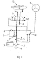
- FIG. 1 shows a tank 1 for hydraulic medium and a steering pump 2, which is driven by a drive 3.
- the drive 3 with the Drive of the industrial truck identical.
- a speed sensor 4 is located on the drive 3 appropriate.
- the hydraulic circuit has a pressure monitor 5 and a check valve 6. Via an electrically unlockable check valve 9, a container 7 with the Hydraulic circuit connectable.
- a gas generation cartridge 8 is on the container 7 appropriate.
- a controller 10 which is connected via signal lines the speed sensor 4, the pressure monitor 5, the gas generation cartridge 8, and an electrically controllable steering valve 11 and a steering wheel 14 in connection stands. Instead of the steering wheel 14, a joystick can also be provided.
- the possible Positions of the steering valve 11 determine the assignment of pressure line and Return line to steering cylinder 12.
- the return line is with tank 1 connected.
- the described device has the following functionality:
- the steering pump 2 is driven by the drive 3 and sucks hydraulic medium from the Tank 1 on.
- the hydraulic medium is fed into the hydraulic circuit.
- the hydraulic circuit is controlled by the electrically controllable one Steering valve 11 interconnected so that the energy that acts on the steering cylinder 12 the direction of travel of the industrial truck according to that on the steering wheel 14 by a driver set specifications for the direction of travel.
- the Control 10 target signals from the steering wheel 14 as input values for the control receive.
- the controller 10 controls the steering valve 11.
- the controller 10 also processes the measured values of the pressure monitoring 5. These measured values serve as input values for controlling the means for activation the gas generating cartridge 8. (The means for activation are not in Figure 1 In the event that the pressure in the hydraulic circuit is below a predetermined If the value drops, the controller 10 becomes the means for activating the gas generation controlled and the gas generation, for example, electrically activated. The pressure drop in the hydraulic circuit is triggered, for example, by a failure of the steering pump 2.
- FIG. 2 shows in detail a housing 7 with a gas generation cartridge 8 and a connecting piece 18, and with a membrane 17, the space 19 for the Separates hydraulic medium from the gas generation cartridge 8.
- the gas production will triggered by an electrical activation 16.
- the use of the separating membrane 17 points the advantage that even gases that are not in contact with the hydraulic medium may come in the gas generation cartridge can be used.
Landscapes
- Engineering & Computer Science (AREA)
- Transportation (AREA)
- Chemical & Material Sciences (AREA)
- Combustion & Propulsion (AREA)
- Mechanical Engineering (AREA)
- Structural Engineering (AREA)
- Civil Engineering (AREA)
- Life Sciences & Earth Sciences (AREA)
- Geology (AREA)
- Fluid-Pressure Circuits (AREA)
- Steering-Linkage Mechanisms And Four-Wheel Steering (AREA)
Abstract
Description
- Figur 1
- eine erfindungsgemäße Lenkung eines Flurförderzeugs mit Lenkzylinder, Lenkpumpe, Drucküberwachung, Steuerung und einem Behälter mit Gaserzeugungspatrone
- Figur 2
- einen Behälter mit einer Gaserzeugungspatrone
Claims (14)
- Vorrichtung zur Sicherstellung der Lenkbarkeit eines Flurförderzeugs mit einer hydraulischen Lenkung, dadurch gekennzeichnet, dass mindestens eine Gaserzeugungspatrone (8) sowie ein Mittel (16) zur Aktivierung einer Gaserzeugung vorgesehen sind.
- Vorrichtung nach Anspruch 1, dadurch gekennzeichnet, dass eine Steuerung (10) vorgesehen ist.
- Vorrichtung nach Anspruch 1 oder 2, dadurch gekennzeichnet, dass eine Drucküberwachung (5) für einen Hydraulikkreis der hydraulischen Lenkung vorgesehen ist.
- Vorrichtung nach einem der Ansprüche 1 bis 3, dadurch gekennzeichnet, dass ein Behälter (7) vorgesehen ist, mit dem die Gaserzeugungspatrone (8) in Verbindung steht und dessen Inneres mit dem Hydraulikkreis der Lenkung verbindbar ist.
- Vorrichtung nach Anspruch 4, dadurch gekennzeichnet, dass in dem Behälter (7) eine Membran (17) angebracht ist, die einen für Gas vorgesehenen Raum von einem für Hydraulikmedium vorgesehenen Raum (19) trennt.
- Vorrichtung nach einem der Ansprüche 1 bis 5, dadurch gekennzeichnet, dass als Gaserzeugungspatrone (8) eine pyrotechnische Patrone (8) vorgesehen ist.
- Vorrichtung nach einem der Ansprüche 1 bis 6, dadurch gekennzeichnet, dass als Gaserzeugungspatrone (8) ein Gasdruckbehälter (8) vorgesehen ist.
- Verfahren zur Sicherstellung der Lenkbarkeit eines Flurförderzeugs mit einer hydraulischen Lenkung, dadurch gekennzeichnet, dass bei einem Absinken des Drucks in einem Hydraulikkreis der hydraulischen Lenkung eine Gaserzeugung aktiviert wird.
- Verfahren nach Anspruch 8, dadurch gekennzeichnet, dass zur Gaserzeugung eine Gaserzeugungspatrone (8) eingesetzt wird.
- Verfahren nach Anspruch 8 oder 9, dadurch gekennzeichnet, dass eine Steuerung (10) eingesetzt wird, durch die ein Mittel (16) zur Aktivierung der Gaserzeugung ansteuerbar ist.
- Verfahren nach einem der Ansprüche 8 bis 10, dadurch gekennzeichnet, dass der Druck im Hydraulikkreis der Lenkung gemessen wird.
- Verfahren nach einem der Ansprüche 8 bis 11, dadurch gekennzeichnet, dass für den Fall, dass mindestens ein gemessener Druckwert einen bestimmten Grenzwert unterschreitet, die Gaserzeugung aktiviert wird.
- Verfahren nach einem der Ansprüche 8 bis 12, dadurch gekennzeichnet, dass bei Aktivierung der Gaserzeugung das Gas in einen Behälter (7) abgegeben wird, dessen Inneres mit dem Hydraulikkreis verbindbar ist.
- Verfahren nach Anspruch 13, dadurch gekennzeichnet, dass der Behälter (7) so mit dem Hydraulikkreis verbunden wird, dass der durch die Gaserzeugung bedingte Druckaufbau im Behälter (7) dem Druckabfall im Hydraulikkreis entgegenwirkt.
Applications Claiming Priority (2)
| Application Number | Priority Date | Filing Date | Title |
|---|---|---|---|
| DE10111234A DE10111234A1 (de) | 2001-03-08 | 2001-03-08 | Vorrichtung und Verfahren zur Sicherstellung der Lenkbarkeit eines Flurförderzeugs |
| DE10111234 | 2001-03-08 |
Publications (2)
| Publication Number | Publication Date |
|---|---|
| EP1238939A2 true EP1238939A2 (de) | 2002-09-11 |
| EP1238939A3 EP1238939A3 (de) | 2006-01-04 |
Family
ID=7676768
Family Applications (1)
| Application Number | Title | Priority Date | Filing Date |
|---|---|---|---|
| EP02004873A Withdrawn EP1238939A3 (de) | 2001-03-08 | 2002-03-04 | Vorrichtung und Verfahren zur Sicherstellung der Lenkbarkeit eines Flurförderzeugs |
Country Status (3)
| Country | Link |
|---|---|
| US (1) | US6904998B2 (de) |
| EP (1) | EP1238939A3 (de) |
| DE (1) | DE10111234A1 (de) |
Families Citing this family (1)
| Publication number | Priority date | Publication date | Assignee | Title |
|---|---|---|---|---|
| ES2301272B1 (es) * | 2005-01-14 | 2009-05-01 | Exex Pool, S.L. | Dispositivo de seguridad activo en piscinas y en todo medio acuatico. |
Family Cites Families (8)
| Publication number | Priority date | Publication date | Assignee | Title |
|---|---|---|---|---|
| DE7523006U (de) | 1975-07-19 | 1977-02-24 | Bergische Achsenfabrik Fr. Kotz & Soehne, 5276 Wiehl | Ausgleichsbehaelter fuer eine hydraulische lenkung |
| US4619285A (en) * | 1983-06-10 | 1986-10-28 | Futurecraft Corporation | Fluid flow control device |
| US5022481A (en) * | 1990-01-30 | 1991-06-11 | Carter Daniel C | Emergency power steering backup apparatus and method |
| DE19546733C1 (de) | 1995-12-14 | 1997-03-27 | Daimler Benz Ag | Hydraulische Servolenkung |
| DE19605501C1 (de) * | 1996-02-14 | 1997-04-03 | Linde Ag | Flurförderzeug mit einer Fahrerkabine |
| JPH10157639A (ja) | 1996-11-27 | 1998-06-16 | Unisia Jecs Corp | パワーステアリング装置 |
| DE19921436A1 (de) | 1999-05-08 | 2000-11-16 | Daimler Chrysler Ag | Hydraulikanlage |
| DE19926495C2 (de) | 1999-06-10 | 2002-06-20 | Siemens Ag | Energieversorgungssystem für sicherheitsrelevante Systeme in einem Kraftfahrzeug |
-
2001
- 2001-03-08 DE DE10111234A patent/DE10111234A1/de not_active Withdrawn
-
2002
- 2002-03-04 EP EP02004873A patent/EP1238939A3/de not_active Withdrawn
- 2002-03-07 US US10/093,082 patent/US6904998B2/en not_active Expired - Fee Related
Also Published As
| Publication number | Publication date |
|---|---|
| EP1238939A3 (de) | 2006-01-04 |
| DE10111234A1 (de) | 2002-09-26 |
| US6904998B2 (en) | 2005-06-14 |
| US20030005848A1 (en) | 2003-01-09 |
Similar Documents
| Publication | Publication Date | Title |
|---|---|---|
| EP1785325B2 (de) | Steuergerät für eine Druckluftbremsanlage eines Kraftfahrzeugs | |
| EP4396049A1 (de) | Verfahren zum betreiben eines elektropneumatischen bremssystems, ausfallsicherheitsventileinheit, elektropneumatisches bremssystem, fahrzeug | |
| EP1953054B1 (de) | Bremsanlage und Verfahren zum Steuern einer Bremsanlage für ein Nutzfahrzeug | |
| DE102016007362B4 (de) | Notausfahrsystem für ein Flugzeugfahrwerk | |
| DE102020210598A1 (de) | Verfahren zur Prüfung der Verfügbarkeit einer hydraulischen Rückfallebene bei einer elektronisch schlupfregelbaren Fremdkraftbremsanlage; elektronisches Steuergerät für eine elektronisch schlupfregelbare Fremdkraftbremsanlage und elektronisch schlupfregelbare Fremdkraftbremsanlage mit einem elektronischen Steuergerät | |
| EP1417118A2 (de) | Verfahren zur entgasung einer hydraulischen fahrzeugbremsanlage | |
| EP3292031A1 (de) | Verfahren zum betrieb eines parkbremssystems für nutzfahrzeuge, sowie vorrichtung hierzu | |
| DE10154650C1 (de) | Kettenfahrzeug | |
| EP2154041B1 (de) | Druckmittelbetätigte Bremsvorrichtung für Kraftfahrzeuge | |
| DE10324723B4 (de) | Federspeicher-Feststellbremse für Fahrzeuge mit Fremdkraftbremsanlage | |
| EP3925840B1 (de) | Kraftfahrzeug mit druckluftsystem | |
| DE4222219C2 (de) | Anlage für die Zufuhr von Gas unter Druck an druckmittelbetriebene Systeme einer Druckmaschine | |
| EP1731394B1 (de) | Druckluftversorgungseinrichtung | |
| DE10111234A1 (de) | Vorrichtung und Verfahren zur Sicherstellung der Lenkbarkeit eines Flurförderzeugs | |
| DE102010015502A1 (de) | Vorrichtung und Verfahren zum Sensieren und Plausibilitätsüberwachen zumindest eines Drucks | |
| EP1366964A2 (de) | Feststellbremsanlage und Verfahren zum Betreiben einer Feststellbremsanlage | |
| DE102023136454A1 (de) | Elektronisch steuerbares pneumatisches Bremssystem mit einem Umkehrrelaisventil zum Be- und Entlüften eines Federspeicherbremszylinders eines Fahrzeugs | |
| DE102005032219A1 (de) | Steuervorrichtung für eine Luftfederungsanlage eines Kraftfahrzeuges | |
| EP0157309B1 (de) | Überwachungsverfahren für ein Bremssystem | |
| EP4313831B1 (de) | Bremssystem für einen aufzug | |
| DE102016222845B4 (de) | Bremssystem für ein Kraftfahrzeug sowie Verfahren zum Betreiben eines Bremssystems | |
| DE102018219411A1 (de) | Bremssystem für ein Kraftfahrzeug sowie Verfahren zum Betreiben eines Bremssystems | |
| EP1440211A1 (de) | Arbeitsmaschine und verfahren zum betreiben einer arbeitsmaschine | |
| DE10111233A1 (de) | Energiespeicher für hydraulische Anlagen | |
| DE102019203068C5 (de) | Mobilkran und Verfahren zum Einstellen eines Bremsdrucks bei einem derartigen Mobilkran |
Legal Events
| Date | Code | Title | Description |
|---|---|---|---|
| PUAI | Public reference made under article 153(3) epc to a published international application that has entered the european phase |
Free format text: ORIGINAL CODE: 0009012 |
|
| AK | Designated contracting states |
Kind code of ref document: A2 Designated state(s): AT BE CH CY DE DK ES FI FR GB GR IE IT LI LU MC NL PT SE TR |
|
| AX | Request for extension of the european patent |
Free format text: AL;LT;LV;MK;RO;SI |
|
| PUAL | Search report despatched |
Free format text: ORIGINAL CODE: 0009013 |
|
| AK | Designated contracting states |
Kind code of ref document: A3 Designated state(s): AT BE CH CY DE DK ES FI FR GB GR IE IT LI LU MC NL PT SE TR |
|
| AX | Request for extension of the european patent |
Extension state: AL LT LV MK RO SI |
|
| 17P | Request for examination filed |
Effective date: 20060530 |
|
| 17Q | First examination report despatched |
Effective date: 20060710 |
|
| AKX | Designation fees paid |
Designated state(s): DE FR GB IT SE |
|
| GRAP | Despatch of communication of intention to grant a patent |
Free format text: ORIGINAL CODE: EPIDOSNIGR1 |
|
| STAA | Information on the status of an ep patent application or granted ep patent |
Free format text: STATUS: THE APPLICATION IS DEEMED TO BE WITHDRAWN |
|
| 18D | Application deemed to be withdrawn |
Effective date: 20070908 |