EP1238868A1 - Fahrzeuglenkrad - Google Patents
Fahrzeuglenkrad Download PDFInfo
- Publication number
- EP1238868A1 EP1238868A1 EP02003275A EP02003275A EP1238868A1 EP 1238868 A1 EP1238868 A1 EP 1238868A1 EP 02003275 A EP02003275 A EP 02003275A EP 02003275 A EP02003275 A EP 02003275A EP 1238868 A1 EP1238868 A1 EP 1238868A1
- Authority
- EP
- European Patent Office
- Prior art keywords
- cover cap
- steering wheel
- guides
- vehicle steering
- wheel according
- Prior art date
- Legal status (The legal status is an assumption and is not a legal conclusion. Google has not performed a legal analysis and makes no representation as to the accuracy of the status listed.)
- Granted
Links
- 239000006260 foam Substances 0.000 claims description 25
- 238000005187 foaming Methods 0.000 abstract description 3
- 230000004308 accommodation Effects 0.000 abstract 2
- 238000006073 displacement reaction Methods 0.000 description 3
- 238000004512 die casting Methods 0.000 description 1
- 230000037431 insertion Effects 0.000 description 1
- 238000003780 insertion Methods 0.000 description 1
- 239000000463 material Substances 0.000 description 1
- 210000003813 thumb Anatomy 0.000 description 1
Images


Classifications
-
- B—PERFORMING OPERATIONS; TRANSPORTING
- B60—VEHICLES IN GENERAL
- B60R—VEHICLES, VEHICLE FITTINGS, OR VEHICLE PARTS, NOT OTHERWISE PROVIDED FOR
- B60R21/00—Arrangements or fittings on vehicles for protecting or preventing injuries to occupants or pedestrians in case of accidents or other traffic risks
- B60R21/02—Occupant safety arrangements or fittings, e.g. crash pads
- B60R21/16—Inflatable occupant restraints or confinements designed to inflate upon impact or impending impact, e.g. air bags
- B60R21/20—Arrangements for storing inflatable members in their non-use or deflated condition; Arrangement or mounting of air bag modules or components
- B60R21/203—Arrangements for storing inflatable members in their non-use or deflated condition; Arrangement or mounting of air bag modules or components in steering wheels or steering columns
- B60R21/2035—Arrangements for storing inflatable members in their non-use or deflated condition; Arrangement or mounting of air bag modules or components in steering wheels or steering columns using modules containing inflator, bag and cover attachable to the steering wheel as a complete sub-unit
- B60R21/2037—Arrangements for storing inflatable members in their non-use or deflated condition; Arrangement or mounting of air bag modules or components in steering wheels or steering columns using modules containing inflator, bag and cover attachable to the steering wheel as a complete sub-unit the module or a major component thereof being yieldably mounted, e.g. for actuating the horn switch or for protecting the driver in a non-deployment situation
-
- B—PERFORMING OPERATIONS; TRANSPORTING
- B62—LAND VEHICLES FOR TRAVELLING OTHERWISE THAN ON RAILS
- B62D—MOTOR VEHICLES; TRAILERS
- B62D1/00—Steering controls, i.e. means for initiating a change of direction of the vehicle
- B62D1/02—Steering controls, i.e. means for initiating a change of direction of the vehicle vehicle-mounted
- B62D1/04—Hand wheels
-
- Y—GENERAL TAGGING OF NEW TECHNOLOGICAL DEVELOPMENTS; GENERAL TAGGING OF CROSS-SECTIONAL TECHNOLOGIES SPANNING OVER SEVERAL SECTIONS OF THE IPC; TECHNICAL SUBJECTS COVERED BY FORMER USPC CROSS-REFERENCE ART COLLECTIONS [XRACs] AND DIGESTS
- Y10—TECHNICAL SUBJECTS COVERED BY FORMER USPC
- Y10T—TECHNICAL SUBJECTS COVERED BY FORMER US CLASSIFICATION
- Y10T74/00—Machine element or mechanism
- Y10T74/20—Control lever and linkage systems
- Y10T74/20576—Elements
- Y10T74/20732—Handles
- Y10T74/20834—Hand wheels
Definitions
- the invention relates to a vehicle steering wheel with a foamed skeleton and a cover cap mounted axially displaceably for horn actuation which is followed by the foam surrounding the skeleton.
- the invention preferably relates to a vehicle steering wheel with an axially for Horn actuated gas bag module, which is mounted on the cover cap is closed.
- a gap is provided which is as small as possible and should be even.
- the object of the invention is therefore to provide a vehicle steering wheel which the gap is kept small and constant over the circumference. Furthermore are intended for the storage of the cover cap and possibly the gas bag module as few parts as possible are used.
- the task is in a vehicle steering wheel of the type mentioned solved in that in the region of an edge of the cap guides for Cover cap are provided, which are stored in the foam so that they when the cover cap is pressed down on one side for horn actuation tilt by giving in to the foam.
- the guides for Cover cap are provided, which are stored in the foam so that they when the cover cap is pressed down on one side for horn actuation tilt by giving in to the foam.
- Through the tilting movement jamming of the guides prevents. It is through leadership alone that Movement of the cover cap when the horn is actuated is not permitted, but instead additionally by allowing the tilting movement in the compliant Foam. It is therefore deliberately a flexible storage of the leadership in the foam.
- the airbag module with the guides is close to the edge connected to the cover cap and axially together with the cover cap displaceable.
- the gas bag module preferably has one that is open to the cover cap Pot-shaped housing for holding an airbag.
- the edge of the The housing has extensions projecting laterally outwards to the edge of the cover cap, on which the guides attack. Through these extensions the positioning of the guides reached directly at the gap.
- the guides are, for example, in one piece on the receiving housing molded bolts. If the housing is made of plastic, you can the guides can be easily molded onto it. If the bolts as Guides are trained, they also serve to guide return springs, by extending through it. The return springs in turn serve for Resetting the cover cap or the entire gas bag module.
- the guides can be accommodated in bearing bushes, the Bearing bushes are not axially removable on the guides formed by bolts stored and pressed into the foam.
- the bearing bushes By the bearing bushes the entire gas bag module can be held axially non-removable on the bolts be designed together with the bearing bushes as a pre-assembled unit and on Steering wheel can be mounted in that when the module is placed on the Bearing bushes in corresponding receptacles in the foam encasement be pushed in.
- a latching connection between the skeleton and the airbag module is used for mounting of the module insofar as the latching connection takes the module out the steering wheel prevented by unauthorized persons.
- the locking connection is preferably used also the creation of an axial stop in the starting position of the Airbag module, i.e. when the horn is not activated.
- a vehicle steering wheel is shown that a steering wheel skeleton 10 Die-casting material and a foam 12 around the skeleton and a gas bag module 14 has.
- the skeleton 10 and the foam 12 are only in the right half shown cut.
- the gas bag module has a cup-shaped receiving housing which is open at the top 16 made of plastic in which an airbag 18 is received.
- the receiving housing 16 has a bottom 20 and a circumferential side wall 22 with an upper edge 24.
- the receiving housing 16 is through a cover cap 26 closed, which tears open when the gas bag 18 unfolds and one Exits outlet opening.
- the large cover cap 26 has an outer Edge 28, to which in the state shown in FIG. 1 without a paragraph, only by a narrow gap 30 separated, the foam 12 connects.
- the Cover cap 26 completely covers the module on the front.
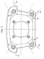
- the guides 32 are made of plastic and are made in one piece on the receiving housing 16 integrally formed, the receiving housing, as can be seen in FIG. 3, on the edge 24 has extensions 36 projecting laterally outwards to the edge 28 of the cover cap 26.
- the guides 32 each have an upward projection 38, which in a receptacle 40 protrudes on the back of the cap 26 in which the guide is recorded without lateral play.
- the individual guides 32 are not directly connected.
- the cap 26 is otherwise firmly connected to the receiving housing 16 via webs, not shown.
- each Guide 32 has a longer shaft section that protrudes downward and itself extends through a return spring 41.
- a bearing bush 42 with one of the System of the return spring 41 serving collar is on each guide 32 from below postponed.
- each guide is thickened to remove the To prevent bearing bushes 42 after unplugging.
- the gas bag module 14 is therefore together with the guides 32 and the bearing bushes 42 at the Assembly from above onto the skeleton 10 together with the surrounding foam 12 (FIG. 5), until the bearing bushes 42 in corresponding recesses 50 in the foam are indented.
- the guides 32 in the foam 12th resiliently mounted, not only axially compliant, but also radially compliant, so that the guides 32 together with bearing bushes 42 in the foam 12 Tilt on the cover cap with lateral pressure.
- hooks 44 On the back of the floor 20 there are hooks 44 as part of a latching connection intended.
- the locking connection is designed so that the locking part 46 together Locking hook 44 in the starting position shown in Figure 1, the stop for the Airbag module 14 forms, but one in the direction of the axis A and down Shift within the latching connection is possible to the horn actuation to allow.
- the axis of rotation 60 is very close to the edge 28, so that with the pivoting of the cap 14 down no substantial radial Relocation of the rim 28 is connected on the right side, and the gap 30 remains essentially the same.
- the minor radial motion components the guides 32 are permitted by the foam 12, the one Allow tilting of the bearing bushes 42.
- FIG. 4 Such a tilting movement of the one shown in the right half of FIG Storage is clearly visible in Figure 4.
- one causes in the area applied force (see also arrow F) tilting the guide 32, 42 in the foam.
- Figure 4b shows a tilting of the Storage in opposite direction; this is caused by depression the cap 14 in the area of the left side of that shown in Figure 2 Storage.
- the axis C is according to Figures 4a and b that of the guide 32 and Axis B is that of opening 50.
- the horn is actuated as soon as horn contacts 62, 64 come into contact have kicked.
Landscapes
- Engineering & Computer Science (AREA)
- Mechanical Engineering (AREA)
- Chemical & Material Sciences (AREA)
- Combustion & Propulsion (AREA)
- Transportation (AREA)
- Air Bags (AREA)
- Steering Controls (AREA)
Abstract
Description
- Figur 1 eine Schnittansicht durch das erfindungsgemäße Lenkrad gemäß einer bevorzugten Ausführungsform bei nichtbetätigter Hupe,
- Figur 2 das Fahrzeuglenkrad nach Figur 1 bei betätigter Hupe,
- Figur 3 eine Ansicht des Gassackmoduls von unten, wobei die Speichen des Lenkrades angedeutet sind,
- die Figuren 4a und 4b ein Nachgeben, d.h. Kippen der Lagerung in verschiedene Richtungen, und
- Figur 5 die Abdeckkappe samt Führung vor dem Einsetzen in die Umschäumung.
Claims (11)
- Fahrzeuglenkrad, mit
einem umschäumten Skelett (10) und
einer zur Hupenbetätigung axial verschiebbar gelagerten Abdeckkappe (26), an welche sich randseitig die Umschäumung (12) des Skeletts (10) anschließt,
dadurch gekennzeichnet, daß im Bereich eines Randes (28) der Abdeckkappe (26) Führungen (32) für die Abdeckkappe (26) vorgesehen sind, die in der Umschäumung (12) so gelagert sind, daß sie beim seitlichen, einseitigen Niederdrücken der Abdeckkappe (26) zur Hupenbetätigung durch ein Nachgeben der Umschäumung (12) kippen. - Fahrzeuglenkrad nach Anspruch 1, gekennzeichnet durch ein von der Abdeckkappe (26) verschlossenes Gassackmodul (14), das zusammen mit der Abdeckkappe (26) axial verschieblich gelagert ist, wobei die Führungen (32) mit dem Gassackmodul (14) verbunden sind.
- Fahrzeuglenkrad nach Anspruch 2, dadurch gekennzeichnet, daß das Gassackmodul ein zur Abdeckkappe (26) offenes topfförmiges Aufnahmegehäuse (16) zur Aufnahme eines Gassacks (18) aufweist, dessen Rand (24) seitlich nach außen zum Rand (28) der Abdeckkappe (26) ragende Fortsätze (36) hat, an denen die Führungen (32) angreifen.
- Fahrzeuglenkrad nach Anspruch 3, dadurch gekennzeichnet, daß die Führungen (32) einstückig an dem Aufnahmegehäuse (16) angeformte Bolzen sind.
- Fahrzeuglenkrad nach Anspruch 3 oder 4, dadurch gekennzeichnet, daß das Aufnahmegehäuse (16) samt Führungen (32) aus Kunststoff ist.
- Fahrzeuglenkrad nach einem der Ansprüche 2 bis 5, dadurch gekennzeichnet, daß eine Rastverbindung zwischen Skelett (10) und Gassackmodul (14) zur Halterung des Gassackmoduls (14) vorgesehen ist.
- Fahrzeuglenkrad nach einem der vorhergehenden Ansprüche, dadurch gekennzeichnet, daß die Führungen (32) Bolzen sind, die sich durch Rückstellfedern (41) erstrecken.
- Fahrzeuglenkrad nach einem der vorhergehenden Ansprüche, dadurch gekennzeichnet, daß die Führungen (32) in Lagerbuchsen (42) aufgenommene Bolzen sind, wobei die Lagerbuchsen (42) axial nicht abziehbar an den Boizen gelagert und in die Umschäumung (12) eingedrückt sind.
- Fahrzeuglenkrad nach einem der vorhergehenden Ansprüche, dadurch gekennzeichnet, daß die Führungen (32) ohne seitliches Spiel in der Abdeckkappe (26) aufgenommen sind.
- Fahrzeuglenkrad nach einem der vorhergehenden Ansprüche, dadurch gekennzeichnet, daß die Abdeckkappe (26) das gesamte Modul vorderseitig abdeckt.
- Fahrzeuglenkrad nach einem der vorhergehenden Ansprüche, dadurch gekennzeichnet, daß die Führungen (32) nicht unmittelbar miteinander verbunden sind.
Applications Claiming Priority (2)
| Application Number | Priority Date | Filing Date | Title |
|---|---|---|---|
| DE20103891U DE20103891U1 (de) | 2001-03-06 | 2001-03-06 | Fahrzeuglenkrad |
| DE20103891U | 2001-03-06 |
Publications (2)
| Publication Number | Publication Date |
|---|---|
| EP1238868A1 true EP1238868A1 (de) | 2002-09-11 |
| EP1238868B1 EP1238868B1 (de) | 2004-09-22 |
Family
ID=7953925
Family Applications (1)
| Application Number | Title | Priority Date | Filing Date |
|---|---|---|---|
| EP02003275A Expired - Lifetime EP1238868B1 (de) | 2001-03-06 | 2002-02-22 | Fahrzeuglenkrad |
Country Status (4)
| Country | Link |
|---|---|
| US (1) | US20020124682A1 (de) |
| EP (1) | EP1238868B1 (de) |
| DE (2) | DE20103891U1 (de) |
| ES (1) | ES2230402T3 (de) |
Cited By (1)
| Publication number | Priority date | Publication date | Assignee | Title |
|---|---|---|---|---|
| DE10250457A1 (de) * | 2002-10-30 | 2004-05-19 | Delphi Technologies, Inc., Troy | Lenkrad eines Kraftfahrzeuges mit einem integrierten Airbagmodul |
Families Citing this family (14)
| Publication number | Priority date | Publication date | Assignee | Title |
|---|---|---|---|---|
| GB2390337A (en) | 2002-07-02 | 2004-01-07 | Autoliv Dev | Steering wheel with airbag centrally and resiliently mounted |
| DE20210741U1 (de) * | 2002-07-16 | 2002-11-28 | TRW Automotive Safety Systems GmbH & Co. KG, 63743 Aschaffenburg | Fahrzeug-Lenkrad |
| DE20304712U1 (de) * | 2003-03-17 | 2003-06-05 | TAKATA-PETRI AG, 63743 Aschaffenburg | Lenkrad mit mindestens einer Vorrichtung zur Befestigung von Anbauteilen |
| US7077427B2 (en) * | 2003-07-16 | 2006-07-18 | Autoliv Asp, Inc. | Steering wheel assembly |
| GB2409715A (en) | 2003-12-31 | 2005-07-06 | Autoliv Dev | Moulding of a plastic steering wheel integral with a metal frame by injecting a propellant to form a cavity |
| DE102009047690A1 (de) * | 2009-12-08 | 2011-06-09 | Takata-Petri Ag | Fahrzeuglenkrad |
| CN103632869B (zh) * | 2012-08-27 | 2016-07-06 | 奥托立夫开发公司 | 车辆方向盘 |
| KR101585098B1 (ko) * | 2013-04-24 | 2016-01-25 | 아우토리브 디벨롭먼트 아베 | 혼 스위치 장치, 에어백 장치, 스티어링 휠 |
| DE102014001821A1 (de) * | 2014-02-13 | 2015-08-13 | Dalphi Metal Espana, S.A. | Vorrichtung zur Positionierung eines Gassackmoduls in einem Kraftfahrzeug |
| DE102014003422B4 (de) * | 2014-03-13 | 2025-02-13 | Dalphi Metal Espana, S.A. | Vorrichtung zur Befestigung eines Gassackmoduls in einem Kraftfahrzeug, Lenkrad, Lenkradbaugruppe sowie Verfahren zur Herstellung einer Lenkradbaugruppe |
| KR101684963B1 (ko) | 2014-12-15 | 2016-12-20 | 아우토리브 디벨롭먼트 아베 | 차량용 혼 스위치 장치 |
| CN110712674B (zh) * | 2018-07-11 | 2022-01-25 | 奥托立夫开发公司 | 方向盘的减震器机构和车辆用方向盘装置 |
| KR102593661B1 (ko) * | 2018-11-13 | 2023-10-25 | 현대모비스 주식회사 | 운전석용 에어백 장치 |
| CN112172908B (zh) * | 2020-09-24 | 2024-07-19 | 盐城同济汽车配件有限公司 | 一种带有减震的方向盘气囊挂钩杆的方向盘骨架 |
Citations (5)
| Publication number | Priority date | Publication date | Assignee | Title |
|---|---|---|---|---|
| EP0717122A1 (de) * | 1994-12-14 | 1996-06-19 | General Motors Corporation | Airbag-System bestehend aus zinkbasislegierten Komponenten |
| DE19852003A1 (de) * | 1997-11-12 | 1999-05-20 | Trw Repa Gmbh | Fahrzeuglenkrad mit integriertem Gassack-Modul |
| EP0945310A2 (de) * | 1998-03-23 | 1999-09-29 | TRW Automotive Safety Systems GmbH & Co. KG | Lenkrad mit Airbag |
| EP1043198A2 (de) * | 1999-04-09 | 2000-10-11 | TRW Automotive Safety Systems GmbH & Co. KG | Lenkrad mit Airbagmodul |
| DE20103890U1 (de) * | 2001-03-06 | 2001-07-12 | TRW Automotive Safety Systems GmbH & Co. KG, 63743 Aschaffenburg | Fahrzeuglenkrad |
Family Cites Families (2)
| Publication number | Priority date | Publication date | Assignee | Title |
|---|---|---|---|---|
| DE19630725A1 (de) * | 1996-07-30 | 1998-02-05 | Bayerische Motoren Werke Ag | Lenkrad mit Airbag-Einheit für Fahrzeuge |
| DE29918481U1 (de) * | 1999-10-21 | 2000-03-02 | TRW Automotive Safety Systems GmbH & Co. KG, 63743 Aschaffenburg | Fahrzeuglenkrad |
-
2001
- 2001-03-06 DE DE20103891U patent/DE20103891U1/de not_active Expired - Lifetime
-
2002
- 2002-02-22 EP EP02003275A patent/EP1238868B1/de not_active Expired - Lifetime
- 2002-02-22 DE DE50201061T patent/DE50201061D1/de not_active Expired - Lifetime
- 2002-02-22 ES ES02003275T patent/ES2230402T3/es not_active Expired - Lifetime
- 2002-02-26 US US10/083,079 patent/US20020124682A1/en not_active Abandoned
Patent Citations (5)
| Publication number | Priority date | Publication date | Assignee | Title |
|---|---|---|---|---|
| EP0717122A1 (de) * | 1994-12-14 | 1996-06-19 | General Motors Corporation | Airbag-System bestehend aus zinkbasislegierten Komponenten |
| DE19852003A1 (de) * | 1997-11-12 | 1999-05-20 | Trw Repa Gmbh | Fahrzeuglenkrad mit integriertem Gassack-Modul |
| EP0945310A2 (de) * | 1998-03-23 | 1999-09-29 | TRW Automotive Safety Systems GmbH & Co. KG | Lenkrad mit Airbag |
| EP1043198A2 (de) * | 1999-04-09 | 2000-10-11 | TRW Automotive Safety Systems GmbH & Co. KG | Lenkrad mit Airbagmodul |
| DE20103890U1 (de) * | 2001-03-06 | 2001-07-12 | TRW Automotive Safety Systems GmbH & Co. KG, 63743 Aschaffenburg | Fahrzeuglenkrad |
Cited By (1)
| Publication number | Priority date | Publication date | Assignee | Title |
|---|---|---|---|---|
| DE10250457A1 (de) * | 2002-10-30 | 2004-05-19 | Delphi Technologies, Inc., Troy | Lenkrad eines Kraftfahrzeuges mit einem integrierten Airbagmodul |
Also Published As
| Publication number | Publication date |
|---|---|
| US20020124682A1 (en) | 2002-09-12 |
| ES2230402T3 (es) | 2005-05-01 |
| EP1238868B1 (de) | 2004-09-22 |
| DE50201061D1 (de) | 2004-10-28 |
| DE20103891U1 (de) | 2002-04-11 |
Similar Documents
| Publication | Publication Date | Title |
|---|---|---|
| EP1238868B1 (de) | Fahrzeuglenkrad | |
| DE102006041734B4 (de) | Vorrichtung zur Befestigung einer Airbageinheit in einer Baugruppe eines Kraftfahrzeugs, insbesondere in einem Lenkrad, durch Verrasten | |
| EP2077203B1 (de) | Halter für einen Getränkebehälter | |
| DE69703235T2 (de) | Vorrichtung zur Herstellung eines Getränkes | |
| DE69821912T2 (de) | Verpackungs- und Ausgabeeinrichtung für ein flüssiges Produkt | |
| DE29723903U1 (de) | Vorrichtung zum Aufbringen eines Etiketts auf eine Compactdisc oder dergleichen | |
| EP0717948B1 (de) | Espresso-Dauerfiltereinsatz | |
| DE60207355T2 (de) | Airbagmodul | |
| DE4015561A1 (de) | Vorrichtung zur montage und fixierung der hydraulikeinheit eines abs | |
| DE3515116A1 (de) | Innenrueckblickspiegel | |
| EP3300936B1 (de) | Lager für ein bauteil eines kraftfahrzeugs | |
| DE69601959T2 (de) | Montagevorrichtung für Rad und mit Laufrädern versehener, mit solcher Vorrichtung ausgerüsteter, Müllsammelbehälter | |
| DE2920836C2 (de) | ||
| DE10150275A1 (de) | Gehäuse für einen aufblasbaren Gassack eines Kraftfahrzeuges | |
| DE102015004089A1 (de) | Filtergehäuse und Filterelement für ein Filtersystem | |
| DE602005003097T2 (de) | Halter mit Schlitz für eine tragbare Vorrichtung | |
| DE19806790B4 (de) | Vorrichtung an einem Betätigungsorgan, insbesondere einer Türgriffanordnung an einem Kraftfahrzeug | |
| DE3517429A1 (de) | Kupplungsmechanismus mit axialer halterung der druckplatte | |
| EP0842815B1 (de) | Aufnahmevorrichtung für Gegenstände in Fahrzeugen | |
| EP3459797A1 (de) | Fahrzeugsensitiver sensor mit mehrteiliger sensormasse | |
| DE102007043560A1 (de) | Fahrzeuglenkrad | |
| EP1145922B1 (de) | Fahrzeuglenkrad mit verschieblich gelagertem Gassackmodul | |
| DE3218569C2 (de) | ||
| DE10317426B4 (de) | Rückhalteelement für Kohlebürsten eines Kommutatormotors | |
| EP1118554A1 (de) | Sprühkappe mit integriertem Sprühkopf |
Legal Events
| Date | Code | Title | Description |
|---|---|---|---|
| PUAI | Public reference made under article 153(3) epc to a published international application that has entered the european phase |
Free format text: ORIGINAL CODE: 0009012 |
|
| AK | Designated contracting states |
Kind code of ref document: A1 Designated state(s): AT BE CH CY DE DK ES FI FR GB GR IE IT LI LU MC NL PT SE TR |
|
| AX | Request for extension of the european patent |
Free format text: AL;LT;LV;MK;RO;SI |
|
| 17P | Request for examination filed |
Effective date: 20030228 |
|
| 17Q | First examination report despatched |
Effective date: 20030408 |
|
| AKX | Designation fees paid |
Designated state(s): DE ES FR GB IT |
|
| GRAP | Despatch of communication of intention to grant a patent |
Free format text: ORIGINAL CODE: EPIDOSNIGR1 |
|
| RAP1 | Party data changed (applicant data changed or rights of an application transferred) |
Owner name: TRW AUTOMOTIVE SAFETY SYSTEMS GMBH |
|
| GRAS | Grant fee paid |
Free format text: ORIGINAL CODE: EPIDOSNIGR3 |
|
| GRAA | (expected) grant |
Free format text: ORIGINAL CODE: 0009210 |
|
| AK | Designated contracting states |
Kind code of ref document: B1 Designated state(s): DE ES FR GB IT |
|
| REG | Reference to a national code |
Ref country code: GB Ref legal event code: FG4D Free format text: NOT ENGLISH |
|
| REG | Reference to a national code |
Ref country code: IE Ref legal event code: FG4D Free format text: GERMAN |
|
| REF | Corresponds to: |
Ref document number: 50201061 Country of ref document: DE Date of ref document: 20041028 Kind code of ref document: P |
|
| GBT | Gb: translation of ep patent filed (gb section 77(6)(a)/1977) |
Effective date: 20041206 |
|
| REG | Reference to a national code |
Ref country code: IE Ref legal event code: FD4D |
|
| REG | Reference to a national code |
Ref country code: ES Ref legal event code: FG2A Ref document number: 2230402 Country of ref document: ES Kind code of ref document: T3 |
|
| PLBE | No opposition filed within time limit |
Free format text: ORIGINAL CODE: 0009261 |
|
| STAA | Information on the status of an ep patent application or granted ep patent |
Free format text: STATUS: NO OPPOSITION FILED WITHIN TIME LIMIT |
|
| ET | Fr: translation filed | ||
| 26N | No opposition filed |
Effective date: 20050623 |
|
| PG25 | Lapsed in a contracting state [announced via postgrant information from national office to epo] |
Ref country code: GB Free format text: LAPSE BECAUSE OF NON-PAYMENT OF DUE FEES Effective date: 20060222 |
|
| GBPC | Gb: european patent ceased through non-payment of renewal fee |
Effective date: 20060222 |
|
| PGFP | Annual fee paid to national office [announced via postgrant information from national office to epo] |
Ref country code: IT Payment date: 20070529 Year of fee payment: 6 |
|
| PGFP | Annual fee paid to national office [announced via postgrant information from national office to epo] |
Ref country code: ES Payment date: 20090218 Year of fee payment: 8 |
|
| PG25 | Lapsed in a contracting state [announced via postgrant information from national office to epo] |
Ref country code: IT Free format text: LAPSE BECAUSE OF NON-PAYMENT OF DUE FEES Effective date: 20080222 |
|
| PGFP | Annual fee paid to national office [announced via postgrant information from national office to epo] |
Ref country code: FR Payment date: 20090206 Year of fee payment: 8 |
|
| REG | Reference to a national code |
Ref country code: FR Ref legal event code: ST Effective date: 20101029 |
|
| PG25 | Lapsed in a contracting state [announced via postgrant information from national office to epo] |
Ref country code: FR Free format text: LAPSE BECAUSE OF NON-PAYMENT OF DUE FEES Effective date: 20100301 |
|
| REG | Reference to a national code |
Ref country code: ES Ref legal event code: FD2A Effective date: 20110308 |
|
| PG25 | Lapsed in a contracting state [announced via postgrant information from national office to epo] |
Ref country code: ES Free format text: LAPSE BECAUSE OF NON-PAYMENT OF DUE FEES Effective date: 20110307 |
|
| PG25 | Lapsed in a contracting state [announced via postgrant information from national office to epo] |
Ref country code: ES Free format text: LAPSE BECAUSE OF NON-PAYMENT OF DUE FEES Effective date: 20100223 |
|
| REG | Reference to a national code |
Ref country code: DE Ref legal event code: R082 Ref document number: 50201061 Country of ref document: DE Representative=s name: PRINZ & PARTNER MBB PATENTANWAELTE RECHTSANWAE, DE Ref country code: DE Ref legal event code: R081 Ref document number: 50201061 Country of ref document: DE Owner name: ZF AUTOMOTIVE SAFETY GERMANY GMBH, DE Free format text: FORMER OWNER: TRW AUTOMOTIVE SAFETY SYSTEMS GMBH & CO. KG, 63743 ASCHAFFENBURG, DE |
|
| PGFP | Annual fee paid to national office [announced via postgrant information from national office to epo] |
Ref country code: DE Payment date: 20210228 Year of fee payment: 20 |
|
| REG | Reference to a national code |
Ref country code: DE Ref legal event code: R071 Ref document number: 50201061 Country of ref document: DE |