EP1238835A2 - Klimagerät - Google Patents
Klimagerät Download PDFInfo
- Publication number
- EP1238835A2 EP1238835A2 EP02002835A EP02002835A EP1238835A2 EP 1238835 A2 EP1238835 A2 EP 1238835A2 EP 02002835 A EP02002835 A EP 02002835A EP 02002835 A EP02002835 A EP 02002835A EP 1238835 A2 EP1238835 A2 EP 1238835A2
- Authority
- EP
- European Patent Office
- Prior art keywords
- air
- shielding element
- radiator
- heat shielding
- cell
- Prior art date
- Legal status (The legal status is an assumption and is not a legal conclusion. Google has not performed a legal analysis and makes no representation as to the accuracy of the status listed.)
- Granted
Links
Images


Classifications
-
- B—PERFORMING OPERATIONS; TRANSPORTING
- B60—VEHICLES IN GENERAL
- B60H—ARRANGEMENTS OF HEATING, COOLING, VENTILATING OR OTHER AIR-TREATING DEVICES SPECIALLY ADAPTED FOR PASSENGER OR GOODS SPACES OF VEHICLES
- B60H1/00—Heating, cooling or ventilating devices
- B60H1/00007—Combined heating, ventilating, or cooling devices
- B60H1/00021—Air flow details of HVAC devices
- B60H1/00028—Constructional lay-out of the devices in the vehicle
-
- B—PERFORMING OPERATIONS; TRANSPORTING
- B60—VEHICLES IN GENERAL
- B60H—ARRANGEMENTS OF HEATING, COOLING, VENTILATING OR OTHER AIR-TREATING DEVICES SPECIALLY ADAPTED FOR PASSENGER OR GOODS SPACES OF VEHICLES
- B60H1/00—Heating, cooling or ventilating devices
- B60H1/00321—Heat exchangers for air-conditioning devices
-
- B—PERFORMING OPERATIONS; TRANSPORTING
- B60—VEHICLES IN GENERAL
- B60H—ARRANGEMENTS OF HEATING, COOLING, VENTILATING OR OTHER AIR-TREATING DEVICES SPECIALLY ADAPTED FOR PASSENGER OR GOODS SPACES OF VEHICLES
- B60H1/00—Heating, cooling or ventilating devices
- B60H1/00507—Details, e.g. mounting arrangements, desaeration devices
- B60H1/00514—Details of air conditioning housings
-
- B—PERFORMING OPERATIONS; TRANSPORTING
- B60—VEHICLES IN GENERAL
- B60H—ARRANGEMENTS OF HEATING, COOLING, VENTILATING OR OTHER AIR-TREATING DEVICES SPECIALLY ADAPTED FOR PASSENGER OR GOODS SPACES OF VEHICLES
- B60H1/00—Heating, cooling or ventilating devices
- B60H1/00007—Combined heating, ventilating, or cooling devices
- B60H1/00021—Air flow details of HVAC devices
- B60H2001/00078—Assembling, manufacturing or layout details
- B60H2001/00092—Assembling, manufacturing or layout details of air deflecting or air directing means inside the device
Definitions
- the invention relates to an air conditioner, in particular for a motor vehicle and further relates to a heat shielding element, in particular according to the Preamble of claim 1, and a heat shielding element according to the preamble of claim 8.
- the invention is based on the problem that at high Cooling requirements for the air conditioner, for example when driving in Midsummer, the air cooled by the cooling heat exchanger through the hot radiator should not be warmed up again or only slightly, when the cold air flows past the radiator. This problem occurs in particular in the case of air conditioning systems regulated on the air side, in which the The hot cooling water flows permanently through the radiator.
- the Air conditioning unit is inexpensive to manufacture, because the additional to be arranged Heat shielding element can be designed extremely inexpensively.
- the Heat shielding element preferably extends flatly on the Air inflow side and / or air outflow side of the radiator, whereby a Reduction of the installation space is possible.
- the heat shielding element is advantageously constructed like a cell, wherein cell walls include flow openings. This is in Direction of flow of the radiator the air flow that in the Radiator enters and / or exits the radiator through which Heat shielding element opposed only a slight resistance, so that by the heat shielding element only a negligible Pressure drop occurs. At the same time a through the heat shield better loading, i.e. a more even flow or
- the throughflow openings are a further development of the invention preferably cell-like or honeycomb-shaped.
- the cell-like Openings have a round or square, preferably square, rectangular, square or hexagonal cross section.
- the honeycomb-like openings have a hexagonal cross section.
- the shielding effect of the heat shielding element be different in some areas. If the Cross-sectional area is smaller, the shielding effect will be greater and vice versa.
- the depth of the heat shielding element can preferably also vary.
- the height of the cell walls is preferably between 6 and 10 mm, which is an optimal compromise between the required installation space and the shielding effect, because the higher the greater the shielding effect will be the cell walls, whereby also the Installation space increases.
- the heat shielding element is preferably the air inflow side or the Cover the air outlet side of the radiator completely.
- the heat shielding element can be detached from the radiator can be fastened, thus, for example, can be plugged on or clipped on.
- the heat shielding element before inserting the Radiator to be plugged or clipped on which hardly Additional effort in the manufacture of the air conditioner arises.
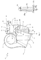
- An air conditioner 10 has an air guide housing 12 in which a blower 14, an air filter 16, a cooling heat exchanger 18, such as a Evaporator, and a radiator 20 to promote and condition the Air are arranged.
- the air is drawn in via the fan 14 and in the direction of the air filter 16 delivered.
- the filtered air is in the cooling heat exchanger 18, the for example, an evaporator of a refrigerant circuit, not shown can be cooled. From the evaporator 18, the cooled air enters one Cold air area 22 on. Any resulting in the evaporator 18 Condensed water can flow out of the drain channel 24 Drain the air duct housing 12.
- the cold air can either through the Radiator 20 guided and heated there and from the radiator 20 enter an air mixing chamber 25 or via a cold air bypass 26, the can be closed with a bypass flap 28 on the radiator 20 passed and enter the air mixing chamber 25. Downstream of the Radiator 20 is a hot air flap 30 is arranged with the Hot air flow can be blocked.
- Defrost air duct 32 which can be closed with a defrost air flap 34 and a ventilation channel 36 which can be closed with a ventilation flap 38, from.
- a footwell air duct 40 branches from the air mixing space 25 from which can also be closed via a flap, not shown can.
- the cooling heat exchanger 18 and the radiator 20 are closely adjacent in parallel. in the maximum cooling operation when the hot air flap 30 is closed all the air exclusively from the cold air room 22 through the Cold air bypass 26 performed, being parallel to the radiator 20 in the direction Bypass channel 26 flows. So that the cold air flows past the Radiator 20 is not heated, according to the invention on one Air inflow side 42 of the radiator 20 has a heat shielding element 44 arranged, on the cold air side 46 cold air can flow past and the warm air duct 48 of the radiator 20 closely adjacent or even on the air inflow side 42 rests directly. It is Heat shielding element 44 received by a receptacle 60, the preferably also receives the radiator. In another The exemplary embodiment is the heat shielding element on the radiator attached, such as attached, clipped or glued and the radiator is taken up by the receiver.
- the heat shielding element 44 is constructed such that it Has openings and over its entire surface essentially the has the same depth.
- FIG. 1a A further exemplary embodiment is shown in FIG. 1a shown with the airflow control or heat shield 44a considered a variable depth in Has air flow direction through the openings. So they are Openings or passages through the heat shield element of different depths. In the lower area, the depth is greater than in the upper area. The depth thus varies with the direction of the Element flowing past air. The airflow control element is thus in the essentially wedge-shaped.
- the depth can also be thought in the height vary, with the part with the greater depth in the lower part of the element is arranged.
- the area of maximum depth be designed such that it is not on an edge area but in a middle zone of the element, in the direction of the flowing past Airflow considered.
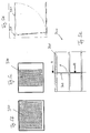
- the heat shielding element shown in FIG. 2 or Airflow control element 44 is preferably constructed in a cell-like manner, wherein Include cell walls 50 throughflow openings 52.
- the Flow openings 52 have a hexagonal cross section, so that the heat shielding element 44 is constructed like a honeycomb.
- Other geometries for example round, square, are and many other geometries, conceivable and possible.
- the cells can regular or irregular or symmetrical or asymmetrical be formed and / or arranged, a plurality of Geometries can be arranged regularly or irregularly distributed.
- Flow openings 52 are of identical design. It is also conceivable that in different areas of the heat shielding element 44, the cross-sectional areas of the flow openings differ could be. For example, the cross-sectional areas in the upper one Area A of the heat shielding element 44 can be made smaller in order to be there increase the heat shielding effect, since more cold air is in the upper area flows past than in the lower area B. However, it can also be useful be when the cells with different sizes across the entire area are distributed as regularly or irregularly. This can be done in Tuning of the radiator, its training and location, selected become.
- the heat shielding element at least partially peripheral edge region 70, which is connected to the honeycomb grid 71 or is formed in one piece with it.
- both Edge area as well as the cell or honeycomb grid made of plastic material, e.g. Polyamide.
- the entire part can be bordered and honeycomb grids can be produced in an injection molding process. Can too the honeycomb grid made of a different or the same material as the Edge area can be produced and joined together with this.
- the height of the cell walls is preferably that of the width D of the Heat shielding element corresponds to between 6 and 15 mm.
- the heat shield 44 preferably completely covers that Air inflow side 42 of the radiator 20 and can schematically clips 54 shown are clipped onto the radiator 20.
- Figures 2a and 2b show sections of the cell grid of the Heat shielding element 200, the cells being uniform in FIG. 2a and are point symmetric and in Figure 2b are the cells Line symmetry., where the height H of the cells is less than the width B.
- the wall thickness W of the cells is in the range of approximately 0.5 mm, preferably between 0.1 mm and 1 mm.
- FIG. 3 shows an air conditioner 100 with an air guide housing 112, in which a blower 114, an air filter 116, a cooling heat exchanger 118, such as for example, an evaporator, and a radiator 120 for conveying and Air conditioning are arranged.
- the air gets through the blower 114 sucked in and discharged in the direction of the air filter 116.
- the filtered Air is in the cooling heat exchanger 118, which is, for example, an evaporator of a refrigerant circuit, not shown, can be cooled.
- the cooling heat exchanger 118 which is, for example, an evaporator of a refrigerant circuit, not shown, can be cooled.
- the cooling heat exchanger 118 which is, for example, an evaporator of a refrigerant circuit, not shown, can be cooled.
- the cooled air enters a cold air area 122.
- any condensate that may occur can be Drain channel 124 run out of air duct housing 112.
- the cold air can either be passed through the heater 120 and heated there and enter from the radiator 120 into an air mixing space 125 or via a cold air bypass 126, which is equipped with a bypass flap 128 is closable, passed the radiator 120 and into the Enter air mixing chamber 125.
- On the upstream side of the radiator 120 is one Warm air damper 130 arranged with the air flow through the radiator can be locked.
- a defrost air duct branches from the air mixing space 125 132, which can be closed with a defrost air flap 134 and a Ventilation duct 136, which can be closed with a ventilation flap 138, from.
- a footwell air duct branches from the air mixing space 125 140, which can also be closed via a flap, not shown can.
- the cooling heat exchanger 118 and the heater 120 closely adjacent to each other in parallel arranged, the flap 130 being arranged between them.
- the flap 130 being arranged between them.
- the maximum cooling operation when the hot air damper 130 is closed all air exclusively from the cold air room 122 through the Cold air bypass 126 performed, parallel to the heater 120 in Flows in the direction of the bypass channel 126.
- the cold air when flowing through the Area 125 is not heated is according to the invention at one Air downstream side 142 of the radiator 120 has a heat shielding element 144 arranged.
- the heat shielding element 144 is of a receptacle 160 added, which preferably also receives the radiator.
- the heat shield attached to the radiator such as attached, clipped or glued on and the radiator is picked up by the holder.
- Figures 4a to 4cv show sections of arrangements of one Heat shielding element, the cell walls 201 in FIG essentially horizontal or parallel to the wall 202 of the at least partially surrounding frame are aligned.
- the walls 210 and 220 are aligned such that an angle between walls of the cells and the frame 211 and 221 is provided so that in the case of FIG. 4b the angle ⁇ is less than 90 ° and in the case of FIG. 4c, the angle ⁇ is greater than 90 °.
- FIG. 5a shows a section of an arrangement a heat shield member 300, with a flap 302 in a cell is arranged and can open and close according to the arrow. The The flap is attached to or arranged on the cell wall 302, such as also formed in one piece if necessary.
- Figures 5b and 5c show schematically embodiments of flap wings 302, the Wing 310 of Figure 5b essentially the entire cross-sectional area closes, the wing of Figure 5c leaves an area and it covers only part of the cross-sectional area.
- 5d shows one Flap wing in section, it can be seen that the wing 330 on one Pivot bearing 331 is suspended.
Landscapes
- Physics & Mathematics (AREA)
- Thermal Sciences (AREA)
- Engineering & Computer Science (AREA)
- Mechanical Engineering (AREA)
- Air-Conditioning For Vehicles (AREA)
Abstract
Description
- Fig. 1
- einen Querschnitt eines Klimagerätes,
- Fig. 1a
- eine Anordnung eines Wärmeabschirmelementes,
- Fig. 2
- eine Ansicht eines Wärmeabschirmelementes,
- Fig. 2a
- ein Ausschnitt eines Wärmeabschirmelements,
- Fig. 2b
- ein Ausschnitt eines Wärmeabschirmelements,
- Fig. 3
- einen Querschnitt eines Klimagerätes,
- Fig. 4a
- ein Schnitt eines Wärmeabschirmelements,
- Fig. 4b
- ein Schnitt eines Wärmeabschirmelements,
- Fig. 4c
- ein Schnitt eines Wärmeabschirmelements,
- Fig. 5a
- ein Schnitt eines Wärmeabschirmelements,
- Fig. 5b
- ein Ausschnitt eines Wärmeabschirmelements,
- Fig. 5c
- ein Ausschnitt eines Wärmeabschirmelements,
- Fig. 5d
- ein Ausschnitt eines Wärmeabschirmelements.
Claims (10)
- Klimagerät, insbesondere für ein Kraftfahrzeug, mit einem Luftführungsgehäuse und darin angeordnetem Kühlwärmetauscher eines Kältemittelkreises zur Abkühlung von Luft, einem Heizkörper zur Erwärmung der Luft und mit Luftstromsteuerungsmitteln, dadurch gekennzeichnet, daß an einer Luftanströmseite und/oder an einer Luftabströmseite des Heizkörpers ein Wärmeabschirmelement angeordnet ist.
- Klimagerät nach Anspruch 1, dadurch gekennzeichnet, daß das Wärmeabschirmelement zellenartig aufgebaut ist, wobei Zellwände Durchströmungsöffnungen einschließen.
- Klimagerät nach Anspruch 2, dadurch gekennzeichnet, daß die Durchströmungsöffnungen einen runden, eckigen oder sechseckigen Querschnitt aufweisen und zellenartig oder wabenartig ausgebildet sind.
- Klimagerät nach einem der vorhergehenden Ansprüche 2 oder 3, dadurch gekennzeichnet, daß die Querschnittsflächen der Durchströmungsöffnungen unterschiedlich ausgebildet sind.
- Klimagerät nach einem der vorhergehenden Ansprüche 2 bis 4, dadurch gekennzeichnet, daß die Höhe (D) der Zellwände zwischen 6 und 15 mm beträgt.
- Klimagerät nach einem der vorhergehenden Ansprüche, dadurch gekennzeichnet, daß das Wärmeabschirmelement die Luftanströmseite vollständig abdeckt.
- Klimagerät nach einem der vorhergehenden Ansprüche, dadurch gekennzeichnet, daß das Wärmeabschirmelement an dem Heizkörper wieder lösbar, insbesondere anklippsbar, befestigt ist.
- Wärmeabschirmelement insbesondere zur Anordnung auf der Anund/oder Abströmseite eines Wärmetauschers, wie Heizkörpers, wobei das Abschirmelement zellenartig ausgebaut ist, wobei die einzelnen Zellen durch Zellwände gebildet sind und einen Durchtritt für ein durchströmendes Medium bilden.
- Wärmeabschirmelement nach Anspruch 8, dadurch gekennzeichnet, daß ein Rahmen und ein zentraler Zellenbereich vorgesehen ist, wobei der Rahmen den zentralen Zellenteil zumindest teilweise umfaßt.
- Wärmeabschirmelement nach Anspruch 9, dadurch gekennzeichnet, daß der Rahmen und der Zellenbereich einstückig ausgebildet ist.
Applications Claiming Priority (2)
| Application Number | Priority Date | Filing Date | Title |
|---|---|---|---|
| DE10110956 | 2001-03-07 | ||
| DE10110956 | 2001-03-07 |
Publications (3)
| Publication Number | Publication Date |
|---|---|
| EP1238835A2 true EP1238835A2 (de) | 2002-09-11 |
| EP1238835A3 EP1238835A3 (de) | 2003-09-17 |
| EP1238835B1 EP1238835B1 (de) | 2008-01-30 |
Family
ID=7676605
Family Applications (1)
| Application Number | Title | Priority Date | Filing Date |
|---|---|---|---|
| EP20020002835 Expired - Lifetime EP1238835B1 (de) | 2001-03-07 | 2002-02-08 | Klimagerät |
Country Status (3)
| Country | Link |
|---|---|
| EP (1) | EP1238835B1 (de) |
| DE (2) | DE10202969A1 (de) |
| ES (1) | ES2299537T3 (de) |
Cited By (2)
| Publication number | Priority date | Publication date | Assignee | Title |
|---|---|---|---|---|
| EP1826042A1 (de) * | 2006-02-28 | 2007-08-29 | Behr GmbH & Co. KG | Kraftfahrzeug-Belüftungssystem |
| FR3102545A1 (fr) * | 2019-10-29 | 2021-04-30 | Valeo Systemes Thermiques | Dispositif de chauffage électrique de véhicule automobile |
Families Citing this family (4)
| Publication number | Priority date | Publication date | Assignee | Title |
|---|---|---|---|---|
| DE102005022368A1 (de) * | 2005-05-10 | 2006-11-16 | Behr Gmbh & Co. Kg | Heizungs- und/oder Klimaanlage |
| DE102010051586A1 (de) * | 2010-11-16 | 2012-05-16 | Daimler Ag | Vorrichtung zur Klimatisierung eines Kraftfahrzeugs |
| DE102014206425A1 (de) | 2014-04-03 | 2015-10-08 | MAHLE Behr GmbH & Co. KG | Klimatisierungssystem |
| US20250178399A1 (en) | 2023-11-30 | 2025-06-05 | Mahle International Gmbh | Housing for multi-flowpath hvac system |
Citations (2)
| Publication number | Priority date | Publication date | Assignee | Title |
|---|---|---|---|---|
| JPS58136813A (ja) | 1982-01-25 | 1983-08-15 | フリ−ダム・インダストリ−ズ・インコ−ポレ−テツド | 旋回信号指示器を有するヘルメツト |
| DE19750381A1 (de) | 1996-11-15 | 1998-05-20 | Denso Corp | Kraftfahrzeug-Klimaanlage |
Family Cites Families (3)
| Publication number | Priority date | Publication date | Assignee | Title |
|---|---|---|---|---|
| DE3710752A1 (de) * | 1986-07-12 | 1988-01-28 | Daimler Benz Ag | Frischluftzufuehreinrichtung |
| DE19505213C1 (de) * | 1995-02-16 | 1996-02-22 | Daimler Benz Ag | Luftzuführeinrichtung |
| DE19951101C1 (de) * | 1999-10-23 | 2000-09-21 | Daimler Chrysler Ag | Klimaanlage für eine Fahrgastzelle eines Fahrzeugs |
-
2002
- 2002-01-26 DE DE10202969A patent/DE10202969A1/de not_active Withdrawn
- 2002-02-08 ES ES02002835T patent/ES2299537T3/es not_active Expired - Lifetime
- 2002-02-08 DE DE50211629T patent/DE50211629D1/de not_active Expired - Lifetime
- 2002-02-08 EP EP20020002835 patent/EP1238835B1/de not_active Expired - Lifetime
Patent Citations (2)
| Publication number | Priority date | Publication date | Assignee | Title |
|---|---|---|---|---|
| JPS58136813A (ja) | 1982-01-25 | 1983-08-15 | フリ−ダム・インダストリ−ズ・インコ−ポレ−テツド | 旋回信号指示器を有するヘルメツト |
| DE19750381A1 (de) | 1996-11-15 | 1998-05-20 | Denso Corp | Kraftfahrzeug-Klimaanlage |
Cited By (2)
| Publication number | Priority date | Publication date | Assignee | Title |
|---|---|---|---|---|
| EP1826042A1 (de) * | 2006-02-28 | 2007-08-29 | Behr GmbH & Co. KG | Kraftfahrzeug-Belüftungssystem |
| FR3102545A1 (fr) * | 2019-10-29 | 2021-04-30 | Valeo Systemes Thermiques | Dispositif de chauffage électrique de véhicule automobile |
Also Published As
| Publication number | Publication date |
|---|---|
| ES2299537T3 (es) | 2008-06-01 |
| EP1238835A3 (de) | 2003-09-17 |
| DE10202969A1 (de) | 2002-09-12 |
| EP1238835B1 (de) | 2008-01-30 |
| DE50211629D1 (de) | 2008-03-20 |
Similar Documents
| Publication | Publication Date | Title |
|---|---|---|
| DE60225979T3 (de) | Vorrichtung zur Erzeugung einer temperaturgeregelten Luftströmung für einen Kraftfahrzeugfahrgastraum und Heizungs- und/oder Klimaanlage mit einer solchen Steuerungsvorrichtung | |
| EP0740617B1 (de) | Heizungs- und/oder klimaeinrichtung | |
| DE10348649A1 (de) | Mehrzonige Kraftfahrzeug-Klimaanlage | |
| DE69725667T2 (de) | Fahrzeugheizgerät | |
| EP2573478B1 (de) | Lüftungsgerät mit Wärmerückgewinnung | |
| DE102008021015A1 (de) | Vorrichtung zur Mischung von gasförmigen Medien und zum Absperren eines Querschnitts | |
| DE102007048331A1 (de) | Klimaanlage für Kraftfahrzeuge | |
| DE3514359C2 (de) | Vorrichtung zum Beheizen und/oder Klimatisieren des Innenraums eines Fahrzeuges | |
| EP1228907B1 (de) | Klimagerät für ein Kraftfahrzeug | |
| EP1238835B1 (de) | Klimagerät | |
| EP1312493B1 (de) | Luftmischeinrichtung für eine Heizungs- oder Klimaanlage | |
| EP2423016B1 (de) | Vorrichtung zur Mischung zweier Luftströme | |
| DE102014209452B4 (de) | Klimaanlage mit Bypassvorrichtung und Verfahren | |
| DE19729899C1 (de) | Heizungs- oder Klimaanlage | |
| EP1721764B1 (de) | Heizungs- und Klimaanlage | |
| DE10147114A1 (de) | Vorrichtung und Verfahren zum Temperieren und Belüften von Kraftfahrzeugen | |
| DE19843322B4 (de) | Heizungs- oder Klimaanlage eines Kraftfahrzeugs | |
| EP3477212B1 (de) | Luftverteilvorrichtung sowie verfahren zur belüftung eines raumes | |
| DE19756166B4 (de) | Luftkanal für eine Heizungs- oder Klimaanlage eines Kraftfahrzeuges sowie damit ausgerüstete Heizungs- oder Klimaanlage | |
| EP1571019B1 (de) | Klimatisierungsvorrichtung, insbesondere für ein Krafffahrzeug | |
| DE102012212470A1 (de) | Klimaanlage | |
| DE3839131C2 (de) | ||
| DE2720714C2 (de) | ||
| DE102005038460B3 (de) | Klimaanlage mit Temperaturmischung in Verbindung mit einem Warmluft- und einem Kaltluftkanal | |
| DE19944531C1 (de) | Klimakasten für Klimaanlagen von Fahrzeugen |
Legal Events
| Date | Code | Title | Description |
|---|---|---|---|
| PUAI | Public reference made under article 153(3) epc to a published international application that has entered the european phase |
Free format text: ORIGINAL CODE: 0009012 |
|
| AK | Designated contracting states |
Kind code of ref document: A2 Designated state(s): AT BE CH CY DE DK ES FI FR GB GR IE IT LI LU MC NL PT SE TR |
|
| AX | Request for extension of the european patent |
Free format text: AL;LT;LV;MK;RO;SI |
|
| PUAL | Search report despatched |
Free format text: ORIGINAL CODE: 0009013 |
|
| AK | Designated contracting states |
Kind code of ref document: A3 Designated state(s): AT BE CH CY DE DK ES FI FR GB GR IE IT LI LU MC NL PT SE TR |
|
| AX | Request for extension of the european patent |
Extension state: AL LT LV MK RO SI |
|
| 17P | Request for examination filed |
Effective date: 20040317 |
|
| AKX | Designation fees paid |
Designated state(s): DE ES FR IT SE |
|
| RAP1 | Party data changed (applicant data changed or rights of an application transferred) |
Owner name: BEHR GMBH & CO. KG |
|
| 17Q | First examination report despatched |
Effective date: 20061218 |
|
| GRAP | Despatch of communication of intention to grant a patent |
Free format text: ORIGINAL CODE: EPIDOSNIGR1 |
|
| GRAS | Grant fee paid |
Free format text: ORIGINAL CODE: EPIDOSNIGR3 |
|
| GRAA | (expected) grant |
Free format text: ORIGINAL CODE: 0009210 |
|
| AK | Designated contracting states |
Kind code of ref document: B1 Designated state(s): DE ES FR IT SE |
|
| REF | Corresponds to: |
Ref document number: 50211629 Country of ref document: DE Date of ref document: 20080320 Kind code of ref document: P |
|
| REG | Reference to a national code |
Ref country code: SE Ref legal event code: TRGR |
|
| PGFP | Annual fee paid to national office [announced via postgrant information from national office to epo] |
Ref country code: ES Payment date: 20080226 Year of fee payment: 7 |
|
| PGFP | Annual fee paid to national office [announced via postgrant information from national office to epo] |
Ref country code: IT Payment date: 20080220 Year of fee payment: 7 |
|
| REG | Reference to a national code |
Ref country code: ES Ref legal event code: FG2A Ref document number: 2299537 Country of ref document: ES Kind code of ref document: T3 |
|
| ET | Fr: translation filed | ||
| PLBE | No opposition filed within time limit |
Free format text: ORIGINAL CODE: 0009261 |
|
| STAA | Information on the status of an ep patent application or granted ep patent |
Free format text: STATUS: NO OPPOSITION FILED WITHIN TIME LIMIT |
|
| 26N | No opposition filed |
Effective date: 20081031 |
|
| REG | Reference to a national code |
Ref country code: ES Ref legal event code: FD2A Effective date: 20090209 |
|
| PGFP | Annual fee paid to national office [announced via postgrant information from national office to epo] |
Ref country code: FR Payment date: 20100225 Year of fee payment: 9 |
|
| PG25 | Lapsed in a contracting state [announced via postgrant information from national office to epo] |
Ref country code: ES Free format text: LAPSE BECAUSE OF NON-PAYMENT OF DUE FEES Effective date: 20090209 |
|
| PGFP | Annual fee paid to national office [announced via postgrant information from national office to epo] |
Ref country code: SE Payment date: 20100216 Year of fee payment: 9 |
|
| PG25 | Lapsed in a contracting state [announced via postgrant information from national office to epo] |
Ref country code: IT Free format text: LAPSE BECAUSE OF NON-PAYMENT OF DUE FEES Effective date: 20090208 |
|
| REG | Reference to a national code |
Ref country code: SE Ref legal event code: EUG |
|
| REG | Reference to a national code |
Ref country code: FR Ref legal event code: ST Effective date: 20111102 |
|
| PG25 | Lapsed in a contracting state [announced via postgrant information from national office to epo] |
Ref country code: FR Free format text: LAPSE BECAUSE OF NON-PAYMENT OF DUE FEES Effective date: 20110228 |
|
| PG25 | Lapsed in a contracting state [announced via postgrant information from national office to epo] |
Ref country code: SE Free format text: LAPSE BECAUSE OF NON-PAYMENT OF DUE FEES Effective date: 20110209 |
|
| REG | Reference to a national code |
Ref country code: DE Ref legal event code: R082 Ref document number: 50211629 Country of ref document: DE Representative=s name: GRAUEL, ANDREAS, DIPL.-PHYS. DR. RER. NAT., DE |
|
| REG | Reference to a national code |
Ref country code: DE Ref legal event code: R082 Ref document number: 50211629 Country of ref document: DE Representative=s name: GRAUEL, ANDREAS, DIPL.-PHYS. DR. RER. NAT., DE Effective date: 20150319 Ref country code: DE Ref legal event code: R081 Ref document number: 50211629 Country of ref document: DE Owner name: MAHLE INTERNATIONAL GMBH, DE Free format text: FORMER OWNER: BEHR GMBH & CO. KG, 70469 STUTTGART, DE Effective date: 20150319 |
|
| PGFP | Annual fee paid to national office [announced via postgrant information from national office to epo] |
Ref country code: DE Payment date: 20210422 Year of fee payment: 20 |