EP1238614B1 - Heizeinsatz für ein elektrisch beheizbares Kochgefäss - Google Patents
Heizeinsatz für ein elektrisch beheizbares Kochgefäss Download PDFInfo
- Publication number
- EP1238614B1 EP1238614B1 EP02004610A EP02004610A EP1238614B1 EP 1238614 B1 EP1238614 B1 EP 1238614B1 EP 02004610 A EP02004610 A EP 02004610A EP 02004610 A EP02004610 A EP 02004610A EP 1238614 B1 EP1238614 B1 EP 1238614B1
- Authority
- EP
- European Patent Office
- Prior art keywords
- metal sheet
- heating insert
- vessel bottom
- vessel
- heating
- Prior art date
- Legal status (The legal status is an assumption and is not a legal conclusion. Google has not performed a legal analysis and makes no representation as to the accuracy of the status listed.)
- Revoked
Links
- 238000010438 heat treatment Methods 0.000 title claims abstract description 74
- 238000010411 cooking Methods 0.000 title claims abstract description 17
- 229910052751 metal Inorganic materials 0.000 claims abstract description 57
- 239000002184 metal Substances 0.000 claims abstract description 57
- 229910000831 Steel Inorganic materials 0.000 claims abstract description 11
- 229910052782 aluminium Inorganic materials 0.000 claims abstract description 11
- XAGFODPZIPBFFR-UHFFFAOYSA-N aluminium Chemical compound [Al] XAGFODPZIPBFFR-UHFFFAOYSA-N 0.000 claims abstract description 11
- 239000010959 steel Substances 0.000 claims abstract description 11
- RYGMFSIKBFXOCR-UHFFFAOYSA-N Copper Chemical compound [Cu] RYGMFSIKBFXOCR-UHFFFAOYSA-N 0.000 claims abstract description 10
- 229910052802 copper Inorganic materials 0.000 claims abstract description 8
- 239000010949 copper Substances 0.000 claims abstract description 8
- 229910045601 alloy Inorganic materials 0.000 claims abstract description 4
- 239000000956 alloy Substances 0.000 claims abstract description 4
- 150000002739 metals Chemical class 0.000 claims abstract description 4
- 238000005476 soldering Methods 0.000 claims description 9
- 230000008878 coupling Effects 0.000 claims description 7
- 238000010168 coupling process Methods 0.000 claims description 7
- 238000005859 coupling reaction Methods 0.000 claims description 7
- 239000000853 adhesive Substances 0.000 claims description 4
- 230000001070 adhesive effect Effects 0.000 claims description 4
- 238000002407 reforming Methods 0.000 claims 2
- 239000010935 stainless steel Substances 0.000 abstract description 6
- 229910001220 stainless steel Inorganic materials 0.000 abstract description 6
- 239000004033 plastic Substances 0.000 description 15
- 229920003023 plastic Polymers 0.000 description 15
- 238000009792 diffusion process Methods 0.000 description 10
- XLYOFNOQVPJJNP-UHFFFAOYSA-N water Substances O XLYOFNOQVPJJNP-UHFFFAOYSA-N 0.000 description 10
- 230000008901 benefit Effects 0.000 description 9
- 239000000463 material Substances 0.000 description 6
- 229910000679 solder Inorganic materials 0.000 description 6
- 239000007788 liquid Substances 0.000 description 4
- 238000000576 coating method Methods 0.000 description 3
- 230000007797 corrosion Effects 0.000 description 3
- 238000005260 corrosion Methods 0.000 description 3
- 230000000694 effects Effects 0.000 description 3
- 238000013021 overheating Methods 0.000 description 3
- 239000004810 polytetrafluoroethylene Substances 0.000 description 3
- 229920001343 polytetrafluoroethylene Polymers 0.000 description 3
- 230000004044 response Effects 0.000 description 3
- 229910000838 Al alloy Inorganic materials 0.000 description 2
- 235000008733 Citrus aurantifolia Nutrition 0.000 description 2
- 235000011941 Tilia x europaea Nutrition 0.000 description 2
- 239000004411 aluminium Substances 0.000 description 2
- 238000004873 anchoring Methods 0.000 description 2
- 230000015572 biosynthetic process Effects 0.000 description 2
- 238000004140 cleaning Methods 0.000 description 2
- 239000011248 coating agent Substances 0.000 description 2
- 238000009826 distribution Methods 0.000 description 2
- 239000004571 lime Substances 0.000 description 2
- 238000004519 manufacturing process Methods 0.000 description 2
- 230000005855 radiation Effects 0.000 description 2
- 230000000087 stabilizing effect Effects 0.000 description 2
- 230000035882 stress Effects 0.000 description 2
- 239000000126 substance Substances 0.000 description 2
- 235000019738 Limestone Nutrition 0.000 description 1
- 238000009835 boiling Methods 0.000 description 1
- 239000004020 conductor Substances 0.000 description 1
- 230000008094 contradictory effect Effects 0.000 description 1
- 230000003247 decreasing effect Effects 0.000 description 1
- 230000001419 dependent effect Effects 0.000 description 1
- 238000011161 development Methods 0.000 description 1
- 230000018109 developmental process Effects 0.000 description 1
- 239000003651 drinking water Substances 0.000 description 1
- 235000020188 drinking water Nutrition 0.000 description 1
- 238000005516 engineering process Methods 0.000 description 1
- 230000002349 favourable effect Effects 0.000 description 1
- 230000004907 flux Effects 0.000 description 1
- 230000001771 impaired effect Effects 0.000 description 1
- JEIPFZHSYJVQDO-UHFFFAOYSA-N iron(III) oxide Inorganic materials O=[Fe]O[Fe]=O JEIPFZHSYJVQDO-UHFFFAOYSA-N 0.000 description 1
- 239000006028 limestone Substances 0.000 description 1
- 230000007774 longterm Effects 0.000 description 1
- 238000000034 method Methods 0.000 description 1
- 229910052759 nickel Inorganic materials 0.000 description 1
- PXHVJJICTQNCMI-UHFFFAOYSA-N nickel Substances [Ni] PXHVJJICTQNCMI-UHFFFAOYSA-N 0.000 description 1
- 239000000049 pigment Substances 0.000 description 1
- 229920000642 polymer Polymers 0.000 description 1
- 230000002028 premature Effects 0.000 description 1
- 230000008569 process Effects 0.000 description 1
- 238000012545 processing Methods 0.000 description 1
- 230000009467 reduction Effects 0.000 description 1
- 230000000717 retained effect Effects 0.000 description 1
- 238000010079 rubber tapping Methods 0.000 description 1
- 230000035939 shock Effects 0.000 description 1
- 238000004901 spalling Methods 0.000 description 1
- 230000006641 stabilisation Effects 0.000 description 1
- 238000011105 stabilization Methods 0.000 description 1
- 239000008399 tap water Substances 0.000 description 1
- 235000020679 tap water Nutrition 0.000 description 1
- 230000008646 thermal stress Effects 0.000 description 1
- 230000002792 vascular Effects 0.000 description 1
- 238000013022 venting Methods 0.000 description 1
- 238000011179 visual inspection Methods 0.000 description 1
- 238000010792 warming Methods 0.000 description 1
Images


Classifications
-
- A—HUMAN NECESSITIES
- A47—FURNITURE; DOMESTIC ARTICLES OR APPLIANCES; COFFEE MILLS; SPICE MILLS; SUCTION CLEANERS IN GENERAL
- A47J—KITCHEN EQUIPMENT; COFFEE MILLS; SPICE MILLS; APPARATUS FOR MAKING BEVERAGES
- A47J27/00—Cooking-vessels
- A47J27/21—Water-boiling vessels, e.g. kettles
- A47J27/21008—Water-boiling vessels, e.g. kettles electrically heated
- A47J27/21041—Water-boiling vessels, e.g. kettles electrically heated with heating elements arranged outside the water vessel
-
- H—ELECTRICITY
- H05—ELECTRIC TECHNIQUES NOT OTHERWISE PROVIDED FOR
- H05B—ELECTRIC HEATING; ELECTRIC LIGHT SOURCES NOT OTHERWISE PROVIDED FOR; CIRCUIT ARRANGEMENTS FOR ELECTRIC LIGHT SOURCES, IN GENERAL
- H05B3/00—Ohmic-resistance heating
- H05B3/78—Heating arrangements specially adapted for immersion heating
- H05B3/82—Fixedly-mounted immersion heaters
-
- A—HUMAN NECESSITIES
- A47—FURNITURE; DOMESTIC ARTICLES OR APPLIANCES; COFFEE MILLS; SPICE MILLS; SUCTION CLEANERS IN GENERAL
- A47J—KITCHEN EQUIPMENT; COFFEE MILLS; SPICE MILLS; APPARATUS FOR MAKING BEVERAGES
- A47J27/00—Cooking-vessels
- A47J27/21—Water-boiling vessels, e.g. kettles
- A47J27/21008—Water-boiling vessels, e.g. kettles electrically heated
- A47J27/21058—Control devices to avoid overheating, i.e. "dry" boiling, or to detect boiling of the water
- A47J27/21066—Details concerning the mounting thereof in or on the water boiling vessel
Definitions
- the invention relates to a heating insert with the in the preamble of claim 1 specified characteristics.
- a heating insert is from the older, but not previously published EP 1 215 939 A2.
- EP 0 285 839 is an electrically heated cooking vessel, in particular for heating drinking water, known which has a heating insert with a stainless steel existing vessel bottom has, at the bottom of a electric radiator in the form of a tubular heater secured by soldering is.
- the heating element is inserted in a container made of plastic.
- Such heating vessels must be equipped with a dry protection, which Ensure that the radiator does not overheat and the plastic container will not be damaged if there is too little or no liquid in the cooking vessel located.
- EP 0 285 839 A2 discloses a profiled Vessel bottom with a sink in the middle and with a sink at the outer edge, which is connected to the plastic vessel.
- the radiator extends in the contrast, higher-lying area of the vessel bottom and at the highest point of the vessel bottom is at the bottom in the immediate Neighborhood of the radiator, a temperature switch or at least the Temperature sensor of a temperature switch arranged.
- a temperature switch or at least the Temperature sensor of a temperature switch arranged. This should be achieved be that with decreasing water level of the bottom area in which the Temperature sensor is arranged, first becomes anhydrous, is heated and characterized triggers the shutdown of the radiator before the water evaporates completely is and the cooking vessel is damaged.
- a cooking vessel is not safe enough, especially in the non-excludable Cases that the cooking vessel is at an angle or in a dry state is turned on. Then it can be damaged by excessive heating of the radiator and / or to shorten its life and come to a damage of the plastic vessel.
- an electrically heatable water vessel which is a heating insert with a stainless steel existing Vessel bottom has, which under formation of a weak elevation in the middle is profiled and at its lowest point on its underside with a tubular heater is soldered. From the tubular heater leads an existing aluminum Thermal bridge to a thermal fuse, which shuts off the tubular heater, if this gets too hot.
- the shape of the vessel bottom is to ensure be that the area of the vessel bottom, under which the Tubular heater is located, can not be above the water surface, and that excessive heating of the tubular heater by means of the thermal bridge, which conducts the heat better than the bottom of the vessel, quickly to a thermal fuse is transmitted.
- the temperature fuse and a temperature controller, which are associated with the heating insert are with the bottom of the vessel bottom screwed.
- a threaded bolt welded, which passes through the thermal bridge.
- the disadvantage is that the point at which the threaded bolt is welded, on the top the vessel bottom is visible. That's undesirable because of it's good looks of the vessel bottom impaired.
- EP 0 636 332 B1 discloses a heating insert for an electric kettle known, the bottom of a vessel made of PTFE coated steel or from having non-oxidizable steel. Except for a raised edge area the vessel bottom, which connects to a plastic vessel produces, the vessel bottom is flat and in its even area with a thermal diffusion plate soldered, which consists of a metal such as aluminum or copper, which conducts heat much better than steel.
- This diffusion plate has a thickness of the order of 2.5 mm to 3 mm, whereas the steel vessel bottom has a thickness of the order of magnitude from 0.3 mm to 1 mm.
- the thermal diffusion plate carries a tubular heater and a temperature limiter.
- the thickness of the thermal diffusion plate is chosen in the order of 2.5 mm to 3 mm to two to meet conflicting demands, namely on the one hand, the heat generated to distribute quickly and on the other hand, the thermal inertia of the Limit heating use; because when you look at the thickness of the thermal diffusion plate increases, at the same time increases the inertia of the heater with the Result that the temperature limiter too slow to a temperature increase the tubular heater reacts; However, reducing the thickness of the thermal Diffusion plate, the heat generated by the tubular heater is not so quickly distributed over the bottom of the vessel.
- the vessel bottom of a heating insert according to the invention consists mostly of a tap water corrosion resistant first metal, in particular made of a stainless steel, which compared to metals such as aluminum and copper is a poor conductor of heat. Under a metal in the sense of the application will also understood an alloy.
- the advantages occur to a considerable extent only with a thickness of the sheet of not more than 1.2 mm.
- the sheet is not more than 1 mm thick, even better, not more than 0.8 mm, which appears to be the optimum.
- a Sheet thickness of less than 0.5 mm is the contribution of the sheet to the dimensional stability the bottom of the vessel too small and it is too expensive or even impossible, the Sheet metal still to attach the temperature limiter or controller to use.
- the vessel bottom is suitably made of steel with one for the intended Purpose - Use in kitchens, especially for water boiling - adequate corrosion resistance.
- the vessel bottom can also be coated be, e.g. with PTFE or other food-grade coating, in particular, one in which foreign substances are bad be liable.
- the sheet does not extend to the edge of the vessel bottom and therefore has no connection to the plastic parts of the cooking vessel. That's simplified the formation of the sheet so that it can be formed just.
- the desired shape-stabilizing effect of the sheet is at the edge of the vessel bottom Not needed, because there the vessel wall has a stabilizing effect exercises.
- the sheet has a hole in the center of the bottom of the vessel.
- the hole is also in the Hole a visual inspection of the solder flow possible. For reasons of symmetry that is Hole expediently circular.
- the radiator is preferably attached to the underside of the sheet. This allows a simple thermal coupling of a temperature limiter the sheet metal to the radiator and is for the assembly of the sheet metal and the radiator at the bottom of the vessel bottom particularly favorable.
- the heat, the the radiator is generated, essentially by the thin sheet, which is a has only low thermal resistance, by the shortest route into the bottom of the vessel and introduced by this in the medium to be heated. Only a small one Part of the heat flows parallel to the bottom of the vessel through the sheet and reaches this way quickly to the temperature limiter or regulator, including the sheet preferably also the means for attaching the temperature limiter or controller having.
- the radiator which is preferably a tubular heater is to solder directly to the bottom of the vessel and the thin sheet in to arrange a certain distance from the radiator in the space defined by it.
- a decoupled in this way from the radiator thin sheet is very well suited to stabilize the shape of the vessel bottom and for mounting to serve a temperature limiter or controller.
- the desired thermal The temperature limiter or controller can be connected to the radiator in in this case by a separate thermal bridge, e.g. by one or two more sheets, which partly on the radiator or rest and partly with the temperature limiter or with its temperature sensor connection to have.
- the other sheet can be done in a similar way as the first Sheet metal attached to the bottom of the vessel bottom, so that the two sheets lie there next to each other.
- the temperature limiter or controller thermally coupled to the radiator.
- the further sheet metal has only a minimum heat capacity;
- a sheet as thin as it is provided according to the invention can be Do not screw down a temperature limiter or controller.
- Dome with a fferbohrung as disclosed in EP 0 870 455 A2
- the inventive Heating insert as a means for attaching the temperature limiter or controller on the sheet more downwardly projecting pins, especially hollow pins, which by deep-drawing the sheet before this with the bottom the vessel bottom is connected.
- the pins or hollow pins are suitable a temperature limiter or regulator with the bottom of the heater to rivet.
- the electric heater is preferably a tubular heater. Its use is cheap and tested. He can flattened by forming and with his flattened side soldered to the bottom of the vessel bottom or sheet and as a result of the flattening its heat better in the bottom of the vessel into and through it. Conveniently, the radiator is from Edge of the vessel bottom spaced to the heat load of the plastic housing to limit the cooking vessel.
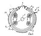
- FIG. 1 shows a plan view of the underside of a heating element 1 for a electric kettle.
- the heating element 1 has a 0.4 mm thick Vessel bottom 2 made of stainless steel, on the underside of a sheet metal 3 is attached, which consists of an aluminum alloy and - apart from the hereinafter explained areas 8, which are made somewhat thinner 0.8 mm thick.
- This sheet 3 is soldered to the vessel bottom 2.
- This sheet 3 is used to attach a - not shown - temperature limiter or controller.
- the sheet 3 has a plurality of downwardly projecting hollow pins 6, which are formed by deep drawing.
- the temperature limiter or regulator is mounted on the plate 3, by means of corresponding openings is placed on the pins 6 and the pins 6 then flattgepreßt become.
- the sheet is used 3 at the same time also the thermal coupling of the temperature limiter or Controller to the soldered to the plate 3 radiator 4 by a support surface for bimetal discs of the temperature limiter or regulator.
- the due to the small thickness of the sheet 3 low heat capacity is this advantageous, since so due to the good thermal conductivity of the sheet 3 - in particular with an empty cooking vessel - the bimetallic discs quickly on their Switching temperature to be heated, without requiring a significant heat flow would be required.
- the sheet 3 has a circular hole 5 in the middle of the vessel bottom 2.
- This hole 5 serves, on the one hand, for the relaxation of stresses which occur when heated due to the different thermal expansion coefficients of the stainless steel existing floor 2 and that of an aluminum alloy existing sheet 3 arise.
- tabs 11 are formed, which for fixing and positioning serve the tubular heater 4 on the plate 3.
- Tabs 11b on the edge of the sheet 3 are used for positioning on the vessel bottom. 2
- FIG. 2 shows a cross-section along the line through that shown in FIG Heating insert 1.
- the radiator 4 Toflächt one side, so that a larger contact surface with the sheet 3 - or as shown in Figures 3 and 4 second embodiment with the vessel bottom 2 - consists.
- Advantageous Thus, a better heat coupling to the vessel bottom 2 and thus that too reaches warming water and improves the load capacity of the solder joint, so that a spalling of the radiator 4 prevented by thermal stresses is.
- the vessel bottom 2 is on the top in contact with water coated with PTFE, so that foreign substances adhere badly and the Cleaning is easier.
- other coatings conceivable and the vessel bottom 2 can also be designed without coating.
- Figure 3 shows another embodiment of a heating insert 1.
- the tubular heater 4 here attached directly to the bottom of the vessel 2 by soldering.
- the temperature limiter or regulator is typically over two bimetal discs with a given switching temperature.
- the sheet 3 is the means for thermal Coupling of the temperature limiter to the radiator 4.
- the heater insert 1 shown in Figure 3 points to this Purpose further sheets 3b, which with the first sheet 3 by narrow Webs 7 are connected. These further sheets 3b are connected to the radiator. 4 soldered and serve to support the bimetallic discs of the temperature limiter.
- the total width of the webs 7 is small compared to the scope of the other sheets 3b, so that only a negligible amount of heat through these webs. 7 flows from the other sheets 3b on the sheet 3; rather, the Main heat flow from these other sheets 3b over the bottom of the vessel 2. Im Case of overheating of the radiator 4 results so an extraordinary short response time of the temperature limiter.
- FIG. 4 shows this heating insert 1 in cross section.
- the vessel bottom 2 includes In this embodiment, a brim, which the anchoring of the vessel bottom supported in the plastic vessel wall of the kettle.
- the vessel bottom 2 has a circular elevation 12 in the middle, which together with the contour of the contoured edge of the hole 5 in Sheet 3 enters a positive engagement and so the positioning of the sheet 3 in the Assembly on the bottom of the vessel 2 facilitates.
- this is also a corresponding depression or other profiling of the surface of the vessel bottom 2 suitable.
- by increasing 12 or another Profiling of the surface also the mechanical stability of the vessel bottom 2 elevated.
- FIG. 5 shows a detail of a cross section through a kettle 20 with a heating insert 1.
- the heating element 1 is over a brim of the vessel bottom 2 anchored in the plastic vessel wall 21, of course Other anchoring options are possible.
- the sheet 3 extends not up to the edge of the vessel bottom 2 and is thus as well as the Radiator 4 from the vessel wall 21 spaced, creating a heat input is minimized by the radiator 4 in the vessel wall 21.
Landscapes
- Engineering & Computer Science (AREA)
- Food Science & Technology (AREA)
- Cookers (AREA)
- Resistance Heating (AREA)
- Baking, Grill, Roasting (AREA)
Description
- einem korrosionsbeständigem Gefäßboden
- einem an der Unterseite des Gefäßbodens angebrachtem Heizkörper
- einer geringen thermischen Trägheit des Heizeinsatzes
- einer hohen Formbeständigkeit bei möglichst ebenem Gefäßboden
- von oben unsichtbaren Befestigungspunkten für einen Temperaturbegrenzer oder -regler und nach
- einem raschen Ansprechen des Temperaturbegrenzers oder -reglers auf ungewollte Temperaturerhöhungen des Heizkörpers
- Verglichen mit den aus der EP 0 636 332 B1 und der EP 0 870 455 A2 bekannten Heizeinsätzen sind die Wärmekapazität und thermische Trägheit des erfindungsgemäßen Heizeinsatzes wesentlich verringert.
- Durch die Verringerung der Menge des einzusetzenden, die Wärme gut leitenden Metalls wie Aluminium oder Kupfer als Material für das Blech lassen sich die Kosten für die Herstellung des Heizeinsatzes gegenüber der EP 0 870 455 A2 um circa 10% bis 30% senken.
- Zur mechanischen Stabilisierung des Gefäßbodens aus einem ersten Metall, welcher eine verhältnismäßig schlechte Wärmeleitfähigkeit hat und deshalb möglichst dünn zu halten ist, vorzugsweise nicht dicker als 0,5 mm, noch besser nicht dicker als 0,4 mm, hat sich ein Blech von 0,5 mm bis 1,2 mm Dicke als völlig ausreichend herausgestellt.
- Das Blech, welches erfindungsgemäß nur noch 0,5 mm bis 1,2 mm dick ist, kann die vom Heizkörper erzeugte Wärme zwar nicht mehr wie eine Wärmeverteilerplatte gemäß der EP 0 870 455 A2 oder wie eine thermische Diffusionsplatte gemäß der EP 0 636 332 B1 schnell und gleichmäßig über den gesamten Boden des Heizeinsatzes verteilen. Das ist aber nur scheinbar ein Nachteil. Tatsächlich erweist sich die Abkehr von der Lehre der EP 0 636 332 A1 und der EP 0 870 455 A2 als vorteilhaft, denn:
- Infolge des höheren Wärmewiderstandes des Blechs in Richtung parallel zum Gefäßboden und des geringeren Wärmewiderstandes von unten nach oben durch den Gefäßboden hindurch wird die vom Heizkörper erzeugte Wärme auf kürzestem Wege in die zu erwärmende Flüssigkeit, insbesondere Wasser, geleitet und kann dort durch Konvektion abgeführt werden.
- Durch den konzentrierteren Wärmefluß durch den Gefäßboden hindurch unmittelbar oberhalb des Heizkörpers platzen unvermeidliche Kalkablagerungen von der Oberseite des Gefäßbodens wieder ab, da die spezifische Heizleistung pro Fläche zunimmt. Auf lange Sicht bleibt die Kalkschicht auf dem Gefäßboden dünner als im Falle eines Heizeinsatzes gemäß der EP 0 870 455 A2 oder gar der EP 0 636 332 B1, bei welchen eine konstante Temperaturverteilung über den Gefäßboden angestrebt wird. Infolge der dünneren Kalkschicht besteht zwischen dem Heizkörper und dem zu beheizenden Medium im Kochgefäß ein geringerer Wärmewiderstand, der eine höhere Lebensdauer des Heizkörpers zur Folge hat, da dieser nicht mehr so heiß wird.
- Anstatt eine höhere Lebensdauer anzustreben kann aber auch bei gleichbleibender Lebensdauer die spezifische Leistung des Heizkörpers erhöht werden, was schnellere Aufheizzeiten und eine weitere Reduzierung der abgelagerten Kalkschicht durch frühzeitigeres Abplatzen der Kalkschicht zur Folge hat.
- Dünnere Kalkschichten bedeuten aber nicht nur einen geringeren Wärmewiderstand, sondern auch eine geringere zu beheizende Masse und dadurch erneut ein schnelleres Aufheizen.
- Wird der Heizkörper durch den geringeren Wärmewiderstand zwischen Heizkörper und zu beheizendem Medium nicht mehr so heiß, gibt er auch nicht mehr so viel Strahlung an das Gehäuse des Kochgefäßes ab, so daß für dieses ein billigerer Kunststoff mit niedrigerer Temperaturbeständigkeit eingesetzt werden kann.
- Werkzeuge, welche für die Fertigung von Heizeinsätzen mit verhältnismäßig dicker Wärmeverteilerplatte an der Unterseite des Gefäßbodens hergestellt wurden, können für das Herstellen erfindungsgemäßer Heizeinsätze weitgehend beibehalten werden. Entsprechendes gilt für die zur Anwendung kommende Verbindungstechnik.
- Es hat sich gezeigt, daß das anstelle einer dickeren Wärmeverteilerplatte erfindungsgemäß zur Anwendung kommende dünne Blech, welches vorzugsweise aus Aluminium oder Kupfer besteht, noch eine hinreichende Wärmekapazität aufweist, um Schockschäden zu verhindern, die auftreten können, wenn in ein überhitztes Kochgefäß plötzlich eine kalte Flüssigkeit eingefüllt wird.
- Ein Blech mit der erfindungsgemäß vorgesehenen Dicke von nur noch 0,5 mm bis 1,2 mm ist ausreichend, um daran einen Temperaturbegrenzer oder -regler anzubringen. Zwar mögen sich die Befestigungspunkte für den Temperaturbegrenzer oder -regler an dem dünnen Blech abzeichnen, sie zeichnen sich aber nicht an der Oberseite des Gefäßbodens ab, mit welchem das dünne Blech flächig verbunden ist.
- Das erfindungsgemäß vorgesehene dünne Blech kann darüberhinaus mit Vorteil verwendet werden, um den Temperaturbegrenzer oder -regler oder wenigstens dessen Temperaturfühler thermisch an den Heizkörper anzukoppeln: Weil das dünne Blech eine geringere Wärmekapazität hat als die aus der EP 0 870 455 A2 bekannte Wärmeverteilerplatte und als die aus der EP 0 636 332 B1 bekannte thermische Diffusionsplatte, pflanzt sich eine Temperaturerhöhung des Heizkörpers über das dünne Blech rascher zum Temperaturbegrenzer oder zu dessen Temperaturfühler fort. Die Wärmemenge, die dabei parallel zum Gefäßboden durch das Blech fließt, ist zwar klein verglichen mit der Wärmemenge, welche quer durch den Gefäßboden fließt, entscheidend ist aber, daß sie die Temperaturerhöhung des Heizkörpers dem Temperaturbegrenzer bzw. dessen Temperaturfühler rasch mitteilt. So kommt es bei einer Überhitzung des Heizkörpers schneller zum Abschalten des Heizkörpers. Das ist ein Gewinn an Sicherheit.
- Der Verzicht der Erfindung darauf, die vom Heizkörper erzeugte Wärme gleichmäßig über den Gefäßboden zu verteilen, führt mithin zu entscheidenden Vorteilen.
- Figur 1
- eine Draufsicht auf die Unterseite eines erfindungsgemäßen Heizeinsatzes,
- Figur 2
- einen Querschnitt durch den in Figur 1 gezeigten Heizeinsatz entlang der Linie aa,
- Figur 3
- eine Draufsicht auf die Unterseite eines weiteren Ausführungsbeispiels eines erfindungsgemäßen Heizeinsatzes,
- Figur 4
- einen Querschnitt entlang der Linie bb durch den in Figur 3 gezeigten Heizeinsatz, und
- Figur 5
- ausschnittsweise einen Querschnitt durch einen Wasserkocher mit Heizeinsatz.
Claims (25)
- Heizeinsatz für ein elektrisch beheizbares Kochgefäß
mit einem Gefäßboden (2) aus einem ersten Metall, welcher an seiner Unterseite mit einem Blech (3b) aus einem zweiten Metall, welches Aluminium, Kupfer oder eine Legierung eines dieser Metalle ist, beschichtet ist, dessen Wärmeleitfähigkeit größer ist als die des ersten Metalls des Gefäßbodens (2), mit einem unter dem Gefäßboden (2) vorgesehenen, den Gefäßboden (2) beheizenden elektrischen Heizkörper (4), welcher als Ruhrhelzkörper ausgebildet ist,
mit Mitteln zum thermischen Ankoppeln eines Temperaturbegrenzers oder -reglers an den Heizkörper (4),
und mit mehreren nach unten vorstehenden Stiften (6) zum Anbringen eines Temperaturbegrenzers oder -reglers an der Unterseite des Blechs (3)
dadurch gekennzeichnet, daß das Blech (3) im Mittel nur 0,5 mm bis 1,2 mm dick ist und dass die Stifte (6) durch Umformen des Blechs (3) gebildet sind. - Heizeinsatz nach Anspruch 1, dadurch gekennzeichnet, daß das Blech (3) im Mittel nicht mehr als 1 mm dick ist.
- Heizeinsatz nach Anspruch 1, dadurch gekennzeichnet, daß das Blech (3) im Mittel nicht mehr als 0,8 mm dick ist.
- Heizeinsatz nach einem der vorstehenden Ansprüche, dadurch gekennzeichnet, daß der Gefäßboden (2) aus einem Stahl besteht.
- Heizeinsetz nach einem der Ansprüche 1 bis 3, dadurch gekennzeichnet, daß der Gefäßboden (2) aus einem auf seiner Oberseite beschichteten Stahl besteht.
- Heizeinsatz nach einem der vorstehenden Ansprüche, dadurch gekennzeichnet, daß der Gefäßboden (2) dort, wo er mit dem Blech (3) beschichtet ist, eben ausgebildet ist.
- Heizeinsatz nach einem der vorstehenden Ansprüche, dadurch gekennzeichnet, daß sich das Blech (3) nicht bis zum Rand des Gefäßbodens (2) erstreckt.
- Heizeinsatz nach einem der vorstehenden Ansprüche, dadurch gekennzeichnet, daß das Blech (3) in der Mitte des Gefäßbodens (2) ein Loch (5) aufweist.
- Heizeinsatz nach Anspruch 8, dadurch gekennzeichnet, daß das Loch (5) kreisrund ist.
- Heizeinsatz nach einem der vorstehenden Ansprüche, dadurch gekennzeichnet, daß der Heizkörper (4) an der Unterseite des Blechs (3) befestigt ist.
- Heizeinsatz nach einem der vorstehenden Ansprüche, dadurch gekennzeichnet, daß das Blech (3) das Mittel zum thermischen Ankoppeln des Temperaturbegrenzers oder -reglers an den Heizkörper (4) ist,
- Heizeinsatz nach Anspruch 11, dadurch gekennzeichnet, daß das Blech (3) die Mittel (6) zum Anbringen des Temperaturbegrenzers oder -reglers aufweist.
- Heizeinsatz nach einem der vorstehenden Ansprüche, dadurch gekennzeichnet, daß an der Unterseite des Gefäßbodens (2) nebeneinander ein erstes Blech (3) mit Mitteln zum Anbringen des Temperaturbegrenzers oder -reglers und wenigstens ein weiteres Blech (3b) zum thermischen Ankoppeln des Temperaturbegrenzers oder -reglers an den Heizkörper (4) vorgesehen sind.
- Heizeinsatz nach einem der vorstehenden Ansprüche, dadurch gekennzeichnet, daß die weiteren Bleche (3b) durch einen oder mehrere Stege (7) mit dem ersten Blech (3) verbunden sind, deren Breite - gegebenenfalls an ihren schmalsten Stellen - für das jeweilige weitere Blech (3b) zusammengenommen klein ist gegen den Umfang des betreffenden weiteren Blechs (3b), welches den Temperaturbegrenzer oder -regler thermisch an den Heizkörper (4) koppelt.
- Heizeinsatz nach einem der vorstehenden Ansprüche, dadurch gekennzeichnet, daß die nach unten vorstehenden Stifte (6) Hohlstifte sind.
- Heizeinsatz nach Anspruch 15, dadurch gekennzeichnet, daß die Stifte (6) durch Tiefziehen des Blechs (3) gebildet sind.
- Heizeinsatz nach Anspruch 15 oder 16, dadurch gekennzeichnet, daß die Dicke des Blechs (3) in einem Bereich (8), der die Stifte (6) unmittelbar umgibt, gegenüber der Dicke des restlichen Blechs (3) vermindert ist.
- Heizeinsatz nach Anspruch 17, dadurch gekennzeichnet, daß das Blech (3) in seinen Bereichen (8) mit verminderter Dicke Rippen (9) aufweist, welche radial in Bezug auf den jeweiligen Stift (6) verlaufen.
- Heizeinsatz nach einem der vorstehenden Ansprüche, dadurch gekennzeichnet, daß aus dem Blech (3) Laschen (11, 11b) ausgebildet sind.
- Heizeinsatz nach einem der vorstehenden Ansprüche, dadurch gekennzeichnet, daß das Blech (3) mit dem Gefäßboden (2) verlötet ist.
- Heizeinsatz nach einem der Ansprüche 1 bis 19, dadurch gekennzeichnet, daß das Blech (3) durch einen hinreichend temperaturbeständigen Leitkleber mit dem Gefäßboden (2) verklebt ist.
- Heizeinsatz nach einem der vorstehenden Ansprüche, dadurch gekennzeichnet, daß der Rohrheizkörper (4) durch Umformen abgeflacht und mit seiner abgeflachten Seite mit der Unterseite des Gefäßbodens (2) oder des Blechs (3) verlötet ist.
- Heizeinsatz nach einem der vorstehenden Ansprüche, dadurch gekennzeichnet, daß der Heizkörper (4) mit Abstand vom Rand des Gefäßbodens (2) angeordnet ist.
- Heizeinsatz nach einem der vorstehenden Ansprüche, dadurch gekennzeichnet, daß der Gefäßboden (2) höchstens 0,5 mm, vorzugsweise höchstens 0,4 mm dick ist.
- Heizeinsatz nach einem der vorstehenden Ansprüche in Verbindung mit Anspruch 8 oder 9, dadurch gekennzeichnet, daß der Gefäßboden (2) In der Mitte eine bevorzugt kreisförmige Erhöhung oder Vertiefung (12) hat, welche zusammen mit dem an die Kontur der Erhöhung oder Vertiefung angepaßten Rand des Lochs (5) in dem Blech (3) einen Formschluß eingeht.
Applications Claiming Priority (2)
| Application Number | Priority Date | Filing Date | Title |
|---|---|---|---|
| DE10112012 | 2001-03-07 | ||
| DE10112012A DE10112012A1 (de) | 2001-03-07 | 2001-03-07 | Heizeinsatz für ein elektrisch beheizbares Kochgefäß |
Publications (2)
| Publication Number | Publication Date |
|---|---|
| EP1238614A1 EP1238614A1 (de) | 2002-09-11 |
| EP1238614B1 true EP1238614B1 (de) | 2005-10-26 |
Family
ID=7677258
Family Applications (1)
| Application Number | Title | Priority Date | Filing Date |
|---|---|---|---|
| EP02004610A Revoked EP1238614B1 (de) | 2001-03-07 | 2002-02-28 | Heizeinsatz für ein elektrisch beheizbares Kochgefäss |
Country Status (3)
| Country | Link |
|---|---|
| EP (1) | EP1238614B1 (de) |
| AT (1) | ATE307520T1 (de) |
| DE (2) | DE10112012A1 (de) |
Families Citing this family (5)
| Publication number | Priority date | Publication date | Assignee | Title |
|---|---|---|---|---|
| FR2876535B1 (fr) * | 2004-10-13 | 2006-12-01 | Seb Sa | Element chauffant |
| GB2497978A (en) * | 2011-12-23 | 2013-07-03 | Otter Controls Ltd | Liquid heating vessel and control |
| EP3013116A1 (de) * | 2014-10-21 | 2016-04-27 | Bleckmann GmbH & Co. KG | Heizungssystemkomponente und Verfahren zur Herstellung davon |
| ITUB20156860A1 (it) * | 2015-12-11 | 2017-06-11 | Gian Luigi Pirovano | Sistema di riscaldamento per contenitori in Acciaio Inox |
| DE102021127666A1 (de) * | 2021-10-25 | 2023-04-27 | Eichenauer Heizelemente Gmbh & Co. Kg | Heizeinrichtung und Verfahren zum Herstellen einer Heizeinrichtung |
Citations (1)
| Publication number | Priority date | Publication date | Assignee | Title |
|---|---|---|---|---|
| EP1215939A2 (de) * | 2000-12-06 | 2002-06-19 | Strix Limited | Heizgefässe für Flüssigkeiten |
Family Cites Families (6)
| Publication number | Priority date | Publication date | Assignee | Title |
|---|---|---|---|---|
| DE3711637A1 (de) * | 1987-04-07 | 1988-10-27 | Ego Elektro Blanc & Fischer | Elektro-heizgefaess |
| FR2708407B1 (fr) * | 1993-07-26 | 1995-09-08 | Seb Sa | Bouilloire électrique comportant un moyen de chauffe simplifié. |
| DE4333417A1 (de) * | 1993-09-30 | 1995-04-06 | Wmf Wuerttemberg Metallwaren | Kochgefäß mit Eigenheizung |
| DE29613481U1 (de) * | 1996-08-03 | 1996-09-19 | Fritz Eichenauer GmbH & Co. KG Fabrik elektr. Spezialartikel, 76870 Kandel | Wasserkochgerät |
| DE29704355U1 (de) * | 1997-03-11 | 1998-04-09 | Fritz Eichenauer Gmbh & Co Kg, 76870 Kandel | Vorrichtung zum Erhitzen von Flüssigkeiten, wie ein Wasserkochgerät |
| DE29710464U1 (de) * | 1997-06-16 | 1997-08-14 | E.G.O. Elektro-Gerätebau Gmbh, 75038 Oberderdingen | Wandungselement |
-
2001
- 2001-03-07 DE DE10112012A patent/DE10112012A1/de not_active Withdrawn
-
2002
- 2002-02-28 EP EP02004610A patent/EP1238614B1/de not_active Revoked
- 2002-02-28 AT AT02004610T patent/ATE307520T1/de not_active IP Right Cessation
- 2002-02-28 DE DE50204642T patent/DE50204642D1/de not_active Expired - Fee Related
Patent Citations (1)
| Publication number | Priority date | Publication date | Assignee | Title |
|---|---|---|---|---|
| EP1215939A2 (de) * | 2000-12-06 | 2002-06-19 | Strix Limited | Heizgefässe für Flüssigkeiten |
Also Published As
| Publication number | Publication date |
|---|---|
| DE50204642D1 (de) | 2005-12-01 |
| DE10112012A1 (de) | 2002-10-02 |
| ATE307520T1 (de) | 2005-11-15 |
| EP1238614A1 (de) | 2002-09-11 |
Similar Documents
| Publication | Publication Date | Title |
|---|---|---|
| DE69421970T3 (de) | Elektrisches Wasserkochgerät mit vereinfachter Heizvorrichtung | |
| DE69520563T4 (de) | Gefässe zum erhitzen von flüssigkeiten | |
| DE60317351T2 (de) | Kochgerät mit einer induktionsheizbasis | |
| DE60101987T2 (de) | Kochgefäss aus Edelstahl mit einem kapsularen Boden, der durch magnetische Induktion heizbar ist | |
| DE19732414A1 (de) | Durchlauferhitzer mit Dickschichtheizelementen | |
| DE3711637A1 (de) | Elektro-heizgefaess | |
| DE2021177A1 (de) | Heizeinheit mit plattenfoermiger Oberflaeche und geringer thermischer Masse | |
| CH654459A5 (de) | Elektrischer strahlungsheizkoerper. | |
| DE10131995B4 (de) | Heizeinsatz für ein elektrisch beheizbares Kochgefäß | |
| DE4333158A1 (de) | Gerät zum Zubereiten von Speisen | |
| EP1238614A1 (de) | Heizeinsatz für ein elektrisch beheizbares Kochgefäss | |
| EP0604886B1 (de) | Elektrisch beheiztes Kochgefäss | |
| DE2751991C2 (de) | ||
| DE60118378T2 (de) | Rohrförmiges heizelement | |
| CH646043A5 (de) | Warmhaltegefaess. | |
| DE20104317U1 (de) | Heizeinsatz für ein elektrisch beheizbares Kochgefäß | |
| DE3716966A1 (de) | Kochgefaess fuer induktionsherde | |
| DE29710464U1 (de) | Wandungselement | |
| DE60110733T2 (de) | Heizgefässe für Flüssigkeiten | |
| DE20110880U1 (de) | Heizeinsatz für ein elektrisch beheizbares Kochgefäß | |
| CH376193A (de) | Elektrische Masse-Kochplatte | |
| DE10312728A1 (de) | Durchlauferhitzer | |
| DE9400205U1 (de) | Elektrischer Durchlauferhitzer | |
| DE4406569A1 (de) | Elektrisch beheizbares Gefäß und Verfahren zur Herstellung des Gefäßes | |
| DE3423472A1 (de) | Kochgeschirr |
Legal Events
| Date | Code | Title | Description |
|---|---|---|---|
| PUAI | Public reference made under article 153(3) epc to a published international application that has entered the european phase |
Free format text: ORIGINAL CODE: 0009012 |
|
| AK | Designated contracting states |
Kind code of ref document: A1 Designated state(s): AT BE CH CY DE DK ES FI FR GB GR IE IT LI LU MC NL PT SE TR |
|
| AX | Request for extension of the european patent |
Free format text: AL;LT;LV;MK;RO;SI |
|
| RAP1 | Party data changed (applicant data changed or rights of an application transferred) |
Owner name: EICHENAUER HEIZELEMENTE GMBH & CO.KG |
|
| 17P | Request for examination filed |
Effective date: 20030208 |
|
| 17Q | First examination report despatched |
Effective date: 20030317 |
|
| AKX | Designation fees paid |
Designated state(s): AT BE CH CY DE DK ES FI FR GB GR IE IT LI LU MC NL PT SE TR |
|
| GRAP | Despatch of communication of intention to grant a patent |
Free format text: ORIGINAL CODE: EPIDOSNIGR1 |
|
| GRAS | Grant fee paid |
Free format text: ORIGINAL CODE: EPIDOSNIGR3 |
|
| GRAA | (expected) grant |
Free format text: ORIGINAL CODE: 0009210 |
|
| AK | Designated contracting states |
Kind code of ref document: B1 Designated state(s): AT BE CH CY DE DK ES FI FR GB GR IE IT LI LU MC NL PT SE TR |
|
| PG25 | Lapsed in a contracting state [announced via postgrant information from national office to epo] |
Ref country code: NL Free format text: LAPSE BECAUSE OF FAILURE TO SUBMIT A TRANSLATION OF THE DESCRIPTION OR TO PAY THE FEE WITHIN THE PRESCRIBED TIME-LIMIT Effective date: 20051026 Ref country code: IE Free format text: LAPSE BECAUSE OF FAILURE TO SUBMIT A TRANSLATION OF THE DESCRIPTION OR TO PAY THE FEE WITHIN THE PRESCRIBED TIME-LIMIT Effective date: 20051026 Ref country code: FI Free format text: LAPSE BECAUSE OF FAILURE TO SUBMIT A TRANSLATION OF THE DESCRIPTION OR TO PAY THE FEE WITHIN THE PRESCRIBED TIME-LIMIT Effective date: 20051026 |
|
| REG | Reference to a national code |
Ref country code: GB Ref legal event code: FG4D Free format text: NOT ENGLISH |
|
| REG | Reference to a national code |
Ref country code: CH Ref legal event code: EP |
|
| REG | Reference to a national code |
Ref country code: IE Ref legal event code: FG4D Free format text: LANGUAGE OF EP DOCUMENT: GERMAN |
|
| REF | Corresponds to: |
Ref document number: 50204642 Country of ref document: DE Date of ref document: 20051201 Kind code of ref document: P |
|
| PG25 | Lapsed in a contracting state [announced via postgrant information from national office to epo] |
Ref country code: DK Free format text: LAPSE BECAUSE OF FAILURE TO SUBMIT A TRANSLATION OF THE DESCRIPTION OR TO PAY THE FEE WITHIN THE PRESCRIBED TIME-LIMIT Effective date: 20060126 Ref country code: SE Free format text: LAPSE BECAUSE OF FAILURE TO SUBMIT A TRANSLATION OF THE DESCRIPTION OR TO PAY THE FEE WITHIN THE PRESCRIBED TIME-LIMIT Effective date: 20060126 Ref country code: GR Free format text: LAPSE BECAUSE OF FAILURE TO SUBMIT A TRANSLATION OF THE DESCRIPTION OR TO PAY THE FEE WITHIN THE PRESCRIBED TIME-LIMIT Effective date: 20060126 |
|
| PG25 | Lapsed in a contracting state [announced via postgrant information from national office to epo] |
Ref country code: ES Free format text: LAPSE BECAUSE OF FAILURE TO SUBMIT A TRANSLATION OF THE DESCRIPTION OR TO PAY THE FEE WITHIN THE PRESCRIBED TIME-LIMIT Effective date: 20060206 |
|
| GBT | Gb: translation of ep patent filed (gb section 77(6)(a)/1977) |
Effective date: 20060116 |
|
| PG25 | Lapsed in a contracting state [announced via postgrant information from national office to epo] |
Ref country code: LI Free format text: LAPSE BECAUSE OF NON-PAYMENT OF DUE FEES Effective date: 20060228 Ref country code: MC Free format text: LAPSE BECAUSE OF NON-PAYMENT OF DUE FEES Effective date: 20060228 Ref country code: BE Free format text: LAPSE BECAUSE OF NON-PAYMENT OF DUE FEES Effective date: 20060228 Ref country code: LU Free format text: LAPSE BECAUSE OF NON-PAYMENT OF DUE FEES Effective date: 20060228 Ref country code: CH Free format text: LAPSE BECAUSE OF NON-PAYMENT OF DUE FEES Effective date: 20060228 Ref country code: AT Free format text: LAPSE BECAUSE OF NON-PAYMENT OF DUE FEES Effective date: 20060228 |
|
| PG25 | Lapsed in a contracting state [announced via postgrant information from national office to epo] |
Ref country code: PT Free format text: LAPSE BECAUSE OF FAILURE TO SUBMIT A TRANSLATION OF THE DESCRIPTION OR TO PAY THE FEE WITHIN THE PRESCRIBED TIME-LIMIT Effective date: 20060327 |
|
| NLV1 | Nl: lapsed or annulled due to failure to fulfill the requirements of art. 29p and 29m of the patents act | ||
| REG | Reference to a national code |
Ref country code: IE Ref legal event code: FD4D |
|
| ET | Fr: translation filed | ||
| PLBI | Opposition filed |
Free format text: ORIGINAL CODE: 0009260 |
|
| PLAX | Notice of opposition and request to file observation + time limit sent |
Free format text: ORIGINAL CODE: EPIDOSNOBS2 |
|
| 26 | Opposition filed |
Opponent name: BLECKMANN GMBH & CO. KG Effective date: 20060724 |
|
| REG | Reference to a national code |
Ref country code: CH Ref legal event code: PL |
|
| PLAF | Information modified related to communication of a notice of opposition and request to file observations + time limit |
Free format text: ORIGINAL CODE: EPIDOSCOBS2 |
|
| PLBB | Reply of patent proprietor to notice(s) of opposition received |
Free format text: ORIGINAL CODE: EPIDOSNOBS3 |
|
| PGFP | Annual fee paid to national office [announced via postgrant information from national office to epo] |
Ref country code: TR Payment date: 20070226 Year of fee payment: 6 |
|
| BERE | Be: lapsed |
Owner name: EICHENAUER HEIZELEMENTE G.M.B.H. & CO.KG Effective date: 20060228 |
|
| PGFP | Annual fee paid to national office [announced via postgrant information from national office to epo] |
Ref country code: IT Payment date: 20070531 Year of fee payment: 6 |
|
| PGFP | Annual fee paid to national office [announced via postgrant information from national office to epo] |
Ref country code: DE Payment date: 20080107 Year of fee payment: 7 Ref country code: GB Payment date: 20080107 Year of fee payment: 7 |
|
| APBP | Date of receipt of notice of appeal recorded |
Free format text: ORIGINAL CODE: EPIDOSNNOA2O |
|
| APAH | Appeal reference modified |
Free format text: ORIGINAL CODE: EPIDOSCREFNO |
|
| PGFP | Annual fee paid to national office [announced via postgrant information from national office to epo] |
Ref country code: FR Payment date: 20080219 Year of fee payment: 7 |
|
| APBQ | Date of receipt of statement of grounds of appeal recorded |
Free format text: ORIGINAL CODE: EPIDOSNNOA3O |
|
| PG25 | Lapsed in a contracting state [announced via postgrant information from national office to epo] |
Ref country code: CY Free format text: LAPSE BECAUSE OF FAILURE TO SUBMIT A TRANSLATION OF THE DESCRIPTION OR TO PAY THE FEE WITHIN THE PRESCRIBED TIME-LIMIT Effective date: 20051026 |
|
| PG25 | Lapsed in a contracting state [announced via postgrant information from national office to epo] |
Ref country code: IT Free format text: LAPSE BECAUSE OF NON-PAYMENT OF DUE FEES Effective date: 20080228 |
|
| GBPC | Gb: european patent ceased through non-payment of renewal fee |
Effective date: 20090228 |
|
| REG | Reference to a national code |
Ref country code: FR Ref legal event code: ST Effective date: 20091030 |
|
| PG25 | Lapsed in a contracting state [announced via postgrant information from national office to epo] |
Ref country code: DE Free format text: LAPSE BECAUSE OF NON-PAYMENT OF DUE FEES Effective date: 20090901 |
|
| APBU | Appeal procedure closed |
Free format text: ORIGINAL CODE: EPIDOSNNOA9O |
|
| RDAF | Communication despatched that patent is revoked |
Free format text: ORIGINAL CODE: EPIDOSNREV1 |
|
| RDAG | Patent revoked |
Free format text: ORIGINAL CODE: 0009271 |
|
| STAA | Information on the status of an ep patent application or granted ep patent |
Free format text: STATUS: PATENT REVOKED |
|
| PG25 | Lapsed in a contracting state [announced via postgrant information from national office to epo] |
Ref country code: FR Free format text: LAPSE BECAUSE OF NON-PAYMENT OF DUE FEES Effective date: 20090302 Ref country code: GB Free format text: LAPSE BECAUSE OF NON-PAYMENT OF DUE FEES Effective date: 20090228 |
|
| 27W | Patent revoked |
Effective date: 20100305 |
|
| PG25 | Lapsed in a contracting state [announced via postgrant information from national office to epo] |
Ref country code: TR Free format text: LAPSE BECAUSE OF NON-PAYMENT OF DUE FEES Effective date: 20080106 |