EP1238449B1 - Multipulse dye laser - Google Patents
Multipulse dye laser Download PDFInfo
- Publication number
- EP1238449B1 EP1238449B1 EP00982374A EP00982374A EP1238449B1 EP 1238449 B1 EP1238449 B1 EP 1238449B1 EP 00982374 A EP00982374 A EP 00982374A EP 00982374 A EP00982374 A EP 00982374A EP 1238449 B1 EP1238449 B1 EP 1238449B1
- Authority
- EP
- European Patent Office
- Prior art keywords
- laser
- flashlamp
- pulse
- series
- dye laser
- Prior art date
- Legal status (The legal status is an assumption and is not a legal conclusion. Google has not performed a legal analysis and makes no representation as to the accuracy of the status listed.)
- Expired - Lifetime
Links
- 230000005284 excitation Effects 0.000 claims description 59
- 230000005855 radiation Effects 0.000 claims description 34
- 238000000034 method Methods 0.000 claims description 27
- 238000004146 energy storage Methods 0.000 claims description 26
- 230000001965 increasing effect Effects 0.000 claims description 19
- 238000007599 discharging Methods 0.000 claims description 10
- 230000004044 response Effects 0.000 claims description 8
- 238000004891 communication Methods 0.000 claims description 4
- 239000007788 liquid Substances 0.000 claims description 4
- 210000003491 skin Anatomy 0.000 description 18
- 238000011282 treatment Methods 0.000 description 18
- 206010037549 Purpura Diseases 0.000 description 16
- 241001672981 Purpura Species 0.000 description 16
- 208000009056 telangiectasis Diseases 0.000 description 14
- 210000004027 cell Anatomy 0.000 description 12
- 230000001815 facial effect Effects 0.000 description 12
- 206010043189 Telangiectasia Diseases 0.000 description 10
- 238000001816 cooling Methods 0.000 description 9
- 230000005540 biological transmission Effects 0.000 description 8
- 231100000216 vascular lesion Toxicity 0.000 description 8
- 230000001419 dependent effect Effects 0.000 description 7
- 239000003990 capacitor Substances 0.000 description 5
- 210000003743 erythrocyte Anatomy 0.000 description 5
- 239000012530 fluid Substances 0.000 description 5
- 230000008901 benefit Effects 0.000 description 4
- 238000010586 diagram Methods 0.000 description 4
- 238000000862 absorption spectrum Methods 0.000 description 3
- 239000000919 ceramic Substances 0.000 description 3
- 230000000694 effects Effects 0.000 description 3
- 210000002615 epidermis Anatomy 0.000 description 3
- 230000007935 neutral effect Effects 0.000 description 3
- 230000000630 rising effect Effects 0.000 description 3
- 238000003860 storage Methods 0.000 description 3
- 230000001225 therapeutic effect Effects 0.000 description 3
- 210000001519 tissue Anatomy 0.000 description 3
- 208000003367 Hypopigmentation Diseases 0.000 description 2
- XUMBMVFBXHLACL-UHFFFAOYSA-N Melanin Chemical compound O=C1C(=O)C(C2=CNC3=C(C(C(=O)C4=C32)=O)C)=C2C4=CNC2=C1C XUMBMVFBXHLACL-UHFFFAOYSA-N 0.000 description 2
- 230000002159 abnormal effect Effects 0.000 description 2
- 230000009471 action Effects 0.000 description 2
- 238000000429 assembly Methods 0.000 description 2
- 230000000712 assembly Effects 0.000 description 2
- 229910010293 ceramic material Inorganic materials 0.000 description 2
- 230000008859 change Effects 0.000 description 2
- 239000000284 extract Substances 0.000 description 2
- 230000005283 ground state Effects 0.000 description 2
- 230000003425 hypopigmentation Effects 0.000 description 2
- 238000013532 laser treatment Methods 0.000 description 2
- 239000000463 material Substances 0.000 description 2
- 238000005259 measurement Methods 0.000 description 2
- 229910052761 rare earth metal Inorganic materials 0.000 description 2
- 150000002910 rare earth metals Chemical class 0.000 description 2
- 238000005507 spraying Methods 0.000 description 2
- 230000002792 vascular Effects 0.000 description 2
- 206010015150 Erythema Diseases 0.000 description 1
- 206010015866 Extravasation Diseases 0.000 description 1
- 208000032843 Hemorrhage Diseases 0.000 description 1
- 229910052689 Holmium Inorganic materials 0.000 description 1
- 229910052779 Neodymium Inorganic materials 0.000 description 1
- 229910052777 Praseodymium Inorganic materials 0.000 description 1
- XUIMIQQOPSSXEZ-UHFFFAOYSA-N Silicon Chemical compound [Si] XUIMIQQOPSSXEZ-UHFFFAOYSA-N 0.000 description 1
- 208000027418 Wounds and injury Diseases 0.000 description 1
- 230000005856 abnormality Effects 0.000 description 1
- 238000010521 absorption reaction Methods 0.000 description 1
- 238000009825 accumulation Methods 0.000 description 1
- 230000001154 acute effect Effects 0.000 description 1
- 238000000149 argon plasma sintering Methods 0.000 description 1
- 230000002238 attenuated effect Effects 0.000 description 1
- 230000015572 biosynthetic process Effects 0.000 description 1
- BJQHLKABXJIVAM-UHFFFAOYSA-N bis(2-ethylhexyl) phthalate Chemical compound CCCCC(CC)COC(=O)C1=CC=CC=C1C(=O)OCC(CC)CCCC BJQHLKABXJIVAM-UHFFFAOYSA-N 0.000 description 1
- 239000012503 blood component Substances 0.000 description 1
- 210000004204 blood vessel Anatomy 0.000 description 1
- 238000009835 boiling Methods 0.000 description 1
- 230000001427 coherent effect Effects 0.000 description 1
- 239000012809 cooling fluid Substances 0.000 description 1
- 239000002537 cosmetic Substances 0.000 description 1
- 230000006378 damage Effects 0.000 description 1
- 230000008021 deposition Effects 0.000 description 1
- 238000009792 diffusion process Methods 0.000 description 1
- 238000002845 discoloration Methods 0.000 description 1
- 230000009977 dual effect Effects 0.000 description 1
- 231100000321 erythema Toxicity 0.000 description 1
- 238000002474 experimental method Methods 0.000 description 1
- 230000036251 extravasation Effects 0.000 description 1
- 239000000835 fiber Substances 0.000 description 1
- 230000005669 field effect Effects 0.000 description 1
- 238000010304 firing Methods 0.000 description 1
- 239000011521 glass Substances 0.000 description 1
- 238000010438 heat treatment Methods 0.000 description 1
- KJZYNXUDTRRSPN-UHFFFAOYSA-N holmium atom Chemical compound [Ho] KJZYNXUDTRRSPN-UHFFFAOYSA-N 0.000 description 1
- 208000000069 hyperpigmentation Diseases 0.000 description 1
- 230000003810 hyperpigmentation Effects 0.000 description 1
- 230000001976 improved effect Effects 0.000 description 1
- 230000001939 inductive effect Effects 0.000 description 1
- 230000000977 initiatory effect Effects 0.000 description 1
- 208000014674 injury Diseases 0.000 description 1
- 230000003993 interaction Effects 0.000 description 1
- 238000003698 laser cutting Methods 0.000 description 1
- 238000002430 laser surgery Methods 0.000 description 1
- 230000003902 lesion Effects 0.000 description 1
- 229910044991 metal oxide Inorganic materials 0.000 description 1
- 150000004706 metal oxides Chemical class 0.000 description 1
- 238000004021 metal welding Methods 0.000 description 1
- 239000000203 mixture Substances 0.000 description 1
- QEFYFXOXNSNQGX-UHFFFAOYSA-N neodymium atom Chemical compound [Nd] QEFYFXOXNSNQGX-UHFFFAOYSA-N 0.000 description 1
- 229910052755 nonmetal Inorganic materials 0.000 description 1
- 150000002843 nonmetals Chemical class 0.000 description 1
- 230000003287 optical effect Effects 0.000 description 1
- 230000035515 penetration Effects 0.000 description 1
- 238000001782 photodegradation Methods 0.000 description 1
- 230000001766 physiological effect Effects 0.000 description 1
- PUDIUYLPXJFUGB-UHFFFAOYSA-N praseodymium atom Chemical compound [Pr] PUDIUYLPXJFUGB-UHFFFAOYSA-N 0.000 description 1
- 230000008569 process Effects 0.000 description 1
- 239000004065 semiconductor Substances 0.000 description 1
- 229910052710 silicon Inorganic materials 0.000 description 1
- 239000010703 silicon Substances 0.000 description 1
- 210000004927 skin cell Anatomy 0.000 description 1
- 230000036555 skin type Effects 0.000 description 1
- 239000007921 spray Substances 0.000 description 1
- 230000007704 transition Effects 0.000 description 1
- 238000004383 yellowing Methods 0.000 description 1
Images


Classifications
-
- H—ELECTRICITY
- H01—ELECTRIC ELEMENTS
- H01S—DEVICES USING THE PROCESS OF LIGHT AMPLIFICATION BY STIMULATED EMISSION OF RADIATION [LASER] TO AMPLIFY OR GENERATE LIGHT; DEVICES USING STIMULATED EMISSION OF ELECTROMAGNETIC RADIATION IN WAVE RANGES OTHER THAN OPTICAL
- H01S3/00—Lasers, i.e. devices using stimulated emission of electromagnetic radiation in the infrared, visible or ultraviolet wave range
- H01S3/10—Controlling the intensity, frequency, phase, polarisation or direction of the emitted radiation, e.g. switching, gating, modulating or demodulating
- H01S3/102—Controlling the intensity, frequency, phase, polarisation or direction of the emitted radiation, e.g. switching, gating, modulating or demodulating by controlling the active medium, e.g. by controlling the processes or apparatus for excitation
- H01S3/1022—Controlling the intensity, frequency, phase, polarisation or direction of the emitted radiation, e.g. switching, gating, modulating or demodulating by controlling the active medium, e.g. by controlling the processes or apparatus for excitation by controlling the optical pumping
-
- H—ELECTRICITY
- H01—ELECTRIC ELEMENTS
- H01S—DEVICES USING THE PROCESS OF LIGHT AMPLIFICATION BY STIMULATED EMISSION OF RADIATION [LASER] TO AMPLIFY OR GENERATE LIGHT; DEVICES USING STIMULATED EMISSION OF ELECTROMAGNETIC RADIATION IN WAVE RANGES OTHER THAN OPTICAL
- H01S3/00—Lasers, i.e. devices using stimulated emission of electromagnetic radiation in the infrared, visible or ultraviolet wave range
- H01S3/09—Processes or apparatus for excitation, e.g. pumping
- H01S3/091—Processes or apparatus for excitation, e.g. pumping using optical pumping
- H01S3/0915—Processes or apparatus for excitation, e.g. pumping using optical pumping by incoherent light
- H01S3/092—Processes or apparatus for excitation, e.g. pumping using optical pumping by incoherent light of flash lamp
-
- H—ELECTRICITY
- H01—ELECTRIC ELEMENTS
- H01S—DEVICES USING THE PROCESS OF LIGHT AMPLIFICATION BY STIMULATED EMISSION OF RADIATION [LASER] TO AMPLIFY OR GENERATE LIGHT; DEVICES USING STIMULATED EMISSION OF ELECTROMAGNETIC RADIATION IN WAVE RANGES OTHER THAN OPTICAL
- H01S3/00—Lasers, i.e. devices using stimulated emission of electromagnetic radiation in the infrared, visible or ultraviolet wave range
- H01S3/10—Controlling the intensity, frequency, phase, polarisation or direction of the emitted radiation, e.g. switching, gating, modulating or demodulating
- H01S3/102—Controlling the intensity, frequency, phase, polarisation or direction of the emitted radiation, e.g. switching, gating, modulating or demodulating by controlling the active medium, e.g. by controlling the processes or apparatus for excitation
- H01S3/1022—Controlling the intensity, frequency, phase, polarisation or direction of the emitted radiation, e.g. switching, gating, modulating or demodulating by controlling the active medium, e.g. by controlling the processes or apparatus for excitation by controlling the optical pumping
- H01S3/1024—Controlling the intensity, frequency, phase, polarisation or direction of the emitted radiation, e.g. switching, gating, modulating or demodulating by controlling the active medium, e.g. by controlling the processes or apparatus for excitation by controlling the optical pumping for pulse generation
-
- H—ELECTRICITY
- H01—ELECTRIC ELEMENTS
- H01S—DEVICES USING THE PROCESS OF LIGHT AMPLIFICATION BY STIMULATED EMISSION OF RADIATION [LASER] TO AMPLIFY OR GENERATE LIGHT; DEVICES USING STIMULATED EMISSION OF ELECTROMAGNETIC RADIATION IN WAVE RANGES OTHER THAN OPTICAL
- H01S3/00—Lasers, i.e. devices using stimulated emission of electromagnetic radiation in the infrared, visible or ultraviolet wave range
- H01S3/14—Lasers, i.e. devices using stimulated emission of electromagnetic radiation in the infrared, visible or ultraviolet wave range characterised by the material used as the active medium
- H01S3/20—Liquids
- H01S3/213—Liquids including an organic dye
Definitions
- the present invention relates generally to the field of lasers. More specifically, this invention relates to a method and laser apparatus for producing a pulsed output beam of laser radiation having a long effective pulse duration.
- Facial telangiectasia i.e., abnormal, dilated blood vessels
- the flashlamp-excited pulsed dye laser is an established device for the treatment of various cutaneous vascular lesions including facial telangiectasia. When treated with such a dye laser, most vessels can be cleared with a single treatment, and nearly all vessels can be cleared within three treatments.
- Flashlamp-excited pulsed dye lasers used for treatment of facial telangiectasia typically operate at a wavelength between 585 and 600 nanometers (nm) and a pulse duration of 450 microseconds ( ⁇ sec) to 1.5 milliseconds (msec).
- One of the treatment side effects particularly bothersome to patients is acute post-treatment purpura (i.e., superficial hemorrhage characterized by blue/black discoloration). Purpura is always bothersome, particularly when it appears on the face. Purpura can take one to three weeks to fully resolve and is often quite disruptive in a person's work and social schedules. The acceptance of dye laser treatment would be considerably enhanced if purpura could be minimized or eliminated.
- Various lasers currently used to treat facial telangiectasia generate a continuous pulse having a long pulse duration (i.e., greater than 10 msec).
- the Aura TM laser manufactured by Laserscope, Inc. of San Jose, Calif.
- the Versapulse TM laser manufactured by Coherent, Inc., Medical Group, of Santa Clara, Calif.
- the depth of penetration of the output beam from these solid-state lasers is less than that of a pulsed dye laser beam due to the shorter wavelength (i.e., 532 nm).
- the efficacy in treating deeper and larger telangiectasias is reduced when using one of these solid-state lasers.
- the difficulty in forming a continuous output pulse having a long pulse duration with a flashlamp-excited dye laser is that accumulation of dye molecules in metastable electronic states, thermal distortions in the liquid dye medium (i.e., the gain medium) and photodegradation of the dye all can cause the laser action (i.e. lasing) to self-terminate.
- This self-termination occurs when the lasing threshold (i.e., the excitation energy level at which laser action occurs) rises due to these conditions.
- the lasing threshold i.e., the excitation energy level at which laser action occurs
- U. S. Patent No. 5,287,380 discloses a method of generating an excitation pulse with a ramped amplitude to extend the duration of the output beam of a flashlamp-excited pulsed dye laser.
- U. S. Patent No. 5,598,426 discloses a ramping technique in which the amplitude of the excitation pulse changes in coordination with the lasing threshold to achieve an output beam pulse of extended duration. These patents describe methods that extend the pulse duration of the output beam to about 2 milliseconds.
- U. S. Patent No. 5,746,735 describes optically combining the output beams of multiple lasers to obtain an output beam having a pulse duration of at least one millisecond. However, this technique requires 1 to 2 lasers for each millisecond of pulse duration.
- U.S Patent No. 5 315 607 describes the laser application of Laser Identification of Friend or Foe which requires two laser pulses spaced apart by a minimum of 50 milliseconds to a maximum of 125 milliseconds.
- U.S. Patent No. 5 315 607 discloses a dual pulse flashlamp-pumped laser system having a power supply circuit which not only charges two capacitors which are successively discharged to produce two laser pulses, but also supplies a simmer current through the flashlamp between the pulses.
- the first laser pulse follows a trigger pulse on a flashlamp trigger wire which ionizes the flashlamp gas, permitting a first capacitor to discharge through the flashlamp.
- the simmer current maintains the flashlamp gas in an ionized state, so that a second trigger pulse is not needed.
- the second laser pulse follows an SCR-controlled discharge of the second capacitor through the flashlamp.
- a principle object of the present invention is to provide a flashlamp-excited pulsed dye laser having a long effective pulse duration (on the order of 5 to 40 milliseconds) so as to effectively treat facial telangiectasia (and various other cutaneous vascular lesions) with reduced post-treatment purpura,
- the invention relates to an apparatus and method for generating an output beam of laser radiation having a long effective pulse duration (on the order of 5 to 40 milliseconds).
- a long effective laser pulse duration is desirable to allow thermal diffusion to occur during the time of laser energy deposition.
- An example is treating facial telangiectasia effectively while avoiding purpura.
- Another example is laser cutting and welding of metals and non-metals. While preferred embodiments include a flashlamp-excited pulsed dye laser, the principles of the invention can be advantageously applied to any laser with a dynamically increasing lasing threshold.
- Lasers with dynamically increasing lasing threshold include all lasers in which the lasing transition terminates in an energy level with appreciable thermal population.
- the lasing threshold increases during a laser pulse due to the increase in lower laser level population caused by the increase in temperature of the lasing medium.
- the principles of the present invention can also be advantageously used when the desired laser pulse duration is difficult to generate because the excitation energy required to maintain the laser above lasing threshold for the entire pulse is too great.
- a laser incorporating the principles of the invention generates an output beam comprised of a series of micropulses of laser radiation.
- the series of micropulses constitute an output beam having a long "effective" pulse duration that has been shown to be effective in therapeutic treatment of cutaneous vascular legions while minimizing the undesired side effects of purpura or other hyper-, hypo-pigmentation abnormalities.
- the present invention provides a method as defined by claim 1 of the appended claims.
- the method preferably further includes the steps of measuring a portion of the output beam transmitted through a wavelength filter and adjusting a tuning element in response to the measured portion of the output beam.
- the method includes the step of directing the output beam laser radiation to a target using a flexible aiming device.
- each pulse within the spaced series of excitation pulses has an amplitude that increases in coordination with increasing lasing threshold for the flashlamp-excited dye laser.
- a tuning element is adjusted in coordination with each pulse within the spaced series of excitation pulses to vary the wavelength of each micropulse.
- each micropulse has a pulse duration of at least 10 microseconds.
- each micropulse delivered to the skin has a fluence less than 5j/cm 2 .
- the series of micropulses delivered to the skin has a total fluence greater than 6j/cm 2 .
- each micropulse has an energy level that is less than half of the total energy of the series of micropulses.
- the series of micropulses has a total energy greater than 1 Joule.
- the output beam of laser radiation is directed at the skin of a patient to treat a cutaneous vascular lesion.
- the pulse parameters are selected to minimize the formation of purpura.
- the output beam of laser radiation is aligned with the target using an aiming beam.
- the aiming beam has a wavelength in the green region.
- the present invention provides a flashlamp excited dye laser as defined by claim 11 of the appended claims.
- the laser includes a feedback module and a tuning element.
- the feedback module measures a portion of the output beam transmitted through a wavelength filter.
- the tuning element is in communication with the feedback module and varies the wavelength of each micropulse in response to the measured portion of the output beam.
- the laser may include a flexible aiming device.
- the flexible aiming device is connected to the lasing medium, receives the output beam of the laser radiation and directs the output beam to a target.
- each pulse within the spaced series of excitation pulses is generated with increasing amplitude in coordination with an increasing lasing threshold for the flashlamp-excited dye laser.
- a tuning element is adjusted in coordination with each pulse within the spaced series of excitation pulses to vary the wavelength of each micropulse.
- each micropulse has a pulse duration of at least 10 microseconds.
- each micropulse has an energy level less than half of the total energy of the series of micropulses.
- the series of micropulses has a total energy greater than 1 Joule.
- the output beam of laser radiation is used to treat a cutaneous vascular lesion on a patient's skin.
- the flashlamp-excited dye laser includes an aiming beam for aligning the output beam of laser radiation with the target.
- the aiming beam has a wavelength in the green region.
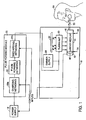
- FIG. 1 depicts a laser system 10 incorporating the principles of the invention.
- the laser system 10 includes a lasing medium 14 comprising an elongated dye cell in which a dye carried by a liquid is dissolved.
- the lasing medium 14 preferably is maintained at a uniform and constant temperature.
- a pulse forming module 20 includes pulse forming networks 22, charging networks 26A and discharging networks 26B.
- the pulse forming networks 22 generate a spaced series of excitation pulses (described in more detail below).
- the pulse forming module 20 applies each excitation pulse through the respective discharging networks 26B, to a flashlamp 30 to excite the lasing medium 14.
- the power supply 18 provides the energy to the pulse forming networks 22.
- the charging networks 26A regulate the amount of energy delivered to each pulse forming network 22.
- a simmer supply 28 supplies a low level current 80 ( FIG. 3A ) to the flashlamp 30 to develop a significant level of ionization in the flashlamp prior to discharge of the flashlamp.
- Each pulse generated by the pulse forming module 20 is discharged through the flashlamp 30, producing a pulse of light of high intensity. More specifically, the high intensity light emanating from the flashlamp 30 is directed to the lasing medium in the dye cell 14.
- a reflector 32 can be used to direct the light to the dye cell. In one embodiment, the reflector 32 encircles the flashlamp 30 and the lasing medium 14.
- the reflector 32 can be made from a white ceramic material. Using a ceramic reflector 32 provides the following advantages: ceramic is resistant to yellowing from light exposure and ceramic can be made into the desired shape prior to firing, so that cost is minimized.
- the lasing medium can include a liquid dye mixture.
- the light from the flashlamp 30 is absorbed by the lasing medium 14 causing dye molecules to move from the ground state to excited singlet states. As the excited molecules return to the ground state, photons of a particular wavelength are emitted. Some of the light emanates from apertures 34, 38 located at each end of the dye cell 14.
- First and second mirror assemblies 42, 46, in combination, constitute an optical system for the laser. The first mirror assembly 42 is fully reflective and returns emanated light back into the dye cell.
- the first mirror assembly 42 can include a wavelength tuning element 48 to tune the output beam within the gain bandwidth of the dye solution.
- The are several tuning techniques known in the art of dye lasers.
- the tuning element 48 can be an intracavity element such as a grating, prism or etalon.
- the tuning element 48 can be a control device that controls the concentration of the dye solution.
- the wavelength tuning element 48 reduces the bandwidth of the beam and can be used to match the wavelength of the laser to the absorption spectrum of the target to enhance the desired physiological effects. As the target cells and surrounding cells heat up, their respective absorption spectra change. In one embodiment, the wavelength of each micropulse is changed to match the peak in the absorption spectrum of the target cells.
- the tuning element 48 is in communication with a synchronizer 182 ( FIG. 4 ) and the synchronizer 182 transmits a series of trigger signals to the tuning element 48. In response to the trigger signals, the tuning element 48 adjusts the wavelength for each subsequent pulse in the spaced series of micropulses of laser radiation 104, 108, 112, 116.
- a second mirror assembly 46 is partially transmissive, returning a portion of the emanated light and allowing the remaining portion to exit the cell.
- the light resonates between the first and second mirror assemblies 42, 46 and increases in intensity when lasing threshold is reached. At that point, a measurable amount of light passes through the second mirror assembly 46 as a pulsed output beam 50.
- the output beam 50 which is comprised of a spaced series of micropulses of laser radiation 88, 92, 96, 100 ( FIG. 3B ), can be aimed at a cutaneous vascular legion 60 (e.g., facial telangiectasia) of the patient 64 being treated.
- FIG. 2A is a detailed representation of the second mirror assembly 46 used in the laser 10.
- the emanated light passes through the aperture 38 at the end of the dye cell 14 to a partially reflective mirror 66.
- the mirror 66 reflects a portion of the light back into the dye cell 14 and transmits a portion of the light to a broadband beamsplitter 300.
- the small amount of reflected light from the beamsplitter 300 is incident on a scatter disc 301, which in one embodiment is made from a ceramic material.
- the light scattering through the disc is optionally attenuated with a neutral density filter 302.
- the light transmitted through the filter 302 is incident on two separate filter/detector pairs.
- the first pair has a neutral density filter 303 and a first detector 68.
- the second pair has a wavelength filter 70 and a second detector 72.
- the wavelength filter 70 provides wavelength dependent transmission of light through it.
- the wavelength filter 70 is glass doped with a rare earth material, for example Praseodymium and Neodymium.
- the wavelength filter 70 is a dielectric coated optic.
- the neutral density filter 302 in one embodiment, is designed to have the same transmission as the wavelength filter 70 at the desired wavelength.
- the first detector 68 and the second detector 72 are in electrical communication with a feedback module 69. In one embodiment, the first and second detectors 69, 72 measure the intensity of the light.
- the wavelength filter 70 permits transmission of light based on a function that is dependent on the wavelength of that light that passes through the wavelength filter 70. This function is represented as a curve, shown graphically in FIG. 2B .
- the feedback module 69 is programmed with the function of transmission dependent on the wavelength of the light.
- the feedback module 69 divides the measurement of the second detector 72 by the measurement of the first detector 68 to determine the amount of light transmitted T 0 through the wavelength filter 70.
- the feedback module 69 uses the point where the calculated amount of light transmitted T 0 intercepts the curve to determine the wavelength ⁇ 0 of the output beam.
- the feedback module uses the function to determine that the wavelength of the output beam has changed from ⁇ 0 to ⁇ 1 .
- a wavelength filter 70 is chosen to provide a transmission function having a steep slope around the operating wavelength of the laser 10.
- flashlamp-excited pulsed dye lasers used for treatment of facial telangiectasia typically operate at a wavelength between 585 and 600 nm.
- a wavelength filter 70 is chosen to provide a transmission function having a steep slope at the wavelength range between 585 and 600 nm.
- a steep slope causes small changes in wavelength to result in large changes in transmission.
- This allows the feedback module 69 to quickly and easily identify changes in wavelength and send an adjustment to the tuning element 48.
- This feedback system (e.g., 48,68,69,70,72) can keep the wavelength of the output beam 50 to a desired tolerance of +/- 1 nm.
- the light passes through optional lenses 304 to a flexible aiming device 74.
- the flexible aiming device 74 allows the user to direct the output beam 50 wherever the user desires without regard to the position of the dye cell 14.
- the flexible aiming device 74 does not alter the wavelength.
- the flexible aiming device 74 is constructed from a fiber optic cable.
- the flexible aiming device has an attached aiming beam device 76.
- the aiming beam device 76 produces an aiming beam 78.
- the aiming beam 78 shows the user where the output beam 50 is aimed.
- the aiming beam has a wavelength in the green region, approximately 490 nm to 550 nm.
- the green wavelength region is used because light in that wavelength range does not disperse on skin cells as much as light in other color ranges. This allows the spot size of the aiming beam to be visibly accurate.
- the spot size of the aiming beam is the same as the spot size of the output beam 50.
- the aiming beam 78 is always present. The user can aim the flexible aiming device 74 until the aiming beam 78 is located directly on the spot the user wants the output beam 50. Once appropriately aimed, the user initiates the triggering of the pulsed output beam 50.
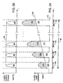
- FIG. 3A depicts a graph of the generated excitation pulses 104, 108, 112, 116.
- FIG. 3B depicts a graph of the output beam 50 corresponding to a series of micropulses 88, 92, 96, 100.
- the horizontal axes for both FIG. 3A and FIG. 3B represent time.
- the vertical axis of FIG. 3A represents the electric current for driving the flashlamp; in this embodiment, current measured in amperes.
- the vertical axis of FIG. 3B represents power of the output beam; in this embodiment, power measured in watts.
- the output beam 50 has an effective pulse duration 84 as shown in FIGS. 3A and 3B .
- the effective pulse duration 84 is defined as the time from the start (i.e., rising edge) of the first micropulse of laser radiation 88 to the end (i.e., falling edge) of the last micropulse of laser radiation 100.
- the output beam 50 is not a continuous pulse of laser radiation, but a time spaced series of micropulses of laser radiation 88, 92, 96, 100.
- the number and amplitude of the excitation pulses 104, 108, 112, 116 determine the number and amplitude of micropulses of laser radiation 88, 92, 96, 100.
- the spacing between the micropulses of laser radiation 88, 92, 96, 100 does not necessarily have to be uniform. In other words, the spacing between the series of excitation pulses 104, 108, 112, 116 can be varied in any way to accomplish the user's goals.
- Each excitation pulse 104, 108, 112, 116 ( FIG. 3A ) is formed using the pulse forming networks 22 and the charging and discharging networks 26A, 26B, as described in more detail below.
- each excitation pulse has more energy than the previous pulse in coordination with an increasing lasing threshold 120.
- the amplitude of each excitation pulse 104, 108, 112, 116 can vary as needed to accomplish various treatment goals. For example, the amplitude of each excitation pulse is coordinated to be greater than the increasing lasing threshold 120. In another embodiment, where the amplitude of each excitation pulse is nearly similar, the duration of each excitation pulse can be increased.
- the increasing lasing threshold 120 is dependent on a variety of factors (as discussed above). In general, the increase in lasing threshold 120 for a dye laser is proportional to the total excitation energy delivered to the dye medium. This energy is, in turn, proportional to the product of the excitation power and the excitation time duration. For a laser incorporating the principles of the invention, the excitation time corresponds to the sum of the excitation times 124, 128, 132, 136 for each of the micropulses of laser radiation 88, 92, 96, 100. Because this sum is significantly shorter than the long effective pulse duration 84, the lasing threshold 120 increases slowly (i.e., smaller slope) relative to traditional continuous pulsed dye lasers.
- the laser 10 generates four pulses, each with a pulse duration 124, 128, 132, 136 of 100 microseconds. Each pulse is spaced so that the time period from the start of the first pulse 88 until the end of the last pulse 100 (i.e., the long effective pulse duration 84) is 10 milliseconds.
- This output beam has a long "effective" pulse duration (i.e., 10 milliseconds), but an actual total "on" time of only 400 microseconds.
- an output beam comprised of a series of micropulses not only helps improve the lasing threshold 120, but also makes the laser more energy efficient.
- the amount of excitation energy converted to output pulse energy corresponds to the sum of the amount of energy of each excitation pulse 104a, 108a, 112a, 116a above the lasing threshold 120.
- a known pulsed dye laser requires excitation energy throughout the entire pulse duration of the output beam. None of the excitation energy below the lasing threshold 120 is converted to output laser radiation.
- the present invention requires excitation energy only when forming each micropulse (i.e., no excitation energy is required between the excitation pulses 104, 108, 112, 116), except for the nominal simmer current 80.
- a laser incorporating the principles of the invention requires less excitation pulse energy to deliver an output beam containing the same amount of laser radiation energy as known pulsed dye lasers. Therefore, a laser incorporating the principles of the invention is more efficient.
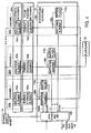
- FIG. 4 is a detailed representation of the pulse forming networks 22 and the charging and discharging networks 26A, 26B used in the laser 10 to form the desired spaced series of excitation pulses 104, 108, 112, 116.
- the pulse forming networks 22, the charging networks 26A and the discharging networks 26B have a plurality of channels 150a, 150b, 150c, each channel corresponding to the creation of a single excitation pulse.
- channel one 150a corresponds to the first excitation pulse 104 ( FIG. 3B )
- channel two 150b corresponds to the second excitation pulse 108 ( FIG. 3B )
- channel n 150c corresponds to the nth or last excitation pulse 116 ( FIG. 3B ).
- each channel is a separate pulse forming network (e.g. channel 1, channel 2, channel n) and includes an energy storage element 160 (e.g., a capacitor).
- the storage element 160 is charged by the power supply 18 prior to the initiation of the spaced series of excitation pulses 104, 108, 112, 116.
- each subsequent excitation pulse needs to have a correspondingly higher amplitude.
- each excitation can have a different amplitude dependent upon the treatment procedure goals.
- each storage element 160 has a different value of capacitance such that a constant voltage from the power supply 18 stores different energies in each channel, as required to meet the treatment goals.
- an inductive element (not shown) is positioned between the pulse forming module 20 and the flashlamp 30. If different values of capacitance are used, the pulse width of each excitation pulse can vary.
- the power supply 18 is a programmable power supply and charges each energy storage element 160, which are all the same value of capacitance, to different voltage levels.
- FIGS. 5A and 5B are a detailed representation of the charging circuit of such an embodiment.
- the switch control module 204 can be a microprocessor controller or a set of circuits made from discrete logic IC's (integrated circuits).
- the switches can be, for example a SCR (silicon controlled rectifier), IGBT (insulated gate bipolar transistor), MOSFET (metal oxide semiconductor field effect transistor), or BJT (bipolar junction transistor).
- the switches can be, for example, a SCR or IGBT, with the driving circuitry.
- the power supply 18 rises in voltage over time, from zero to a predetermined level, as shown in FIG. 5B .
- the switch control module 204 works in coordination with the rising voltage, opening the switch for the respective channel when the desired voltage of that respective channel is reached.
- V a represents the voltage level to which the energy storage device 160a needs to be charged
- V b represents the voltage level to which the energy storage device 160b needs to be charged
- V c represents the voltage level to which the energy storage device 160c needs to be charged.
- the power supply 18 is outputting voltage V a
- the power supply 18 is outputting voltage V b
- the power supply 18 is outputting voltage V b and at time t c, the power supply 18 is outputting voltage V c .
- the switch control module 204 opens switch S a so that the energy storage element 160a of channel 1 is charged only to voltage V a .
- the switch control module 204 opens switch S b so that the energy storage element 160b of channel 2 is charged only to voltage V b and at time t c , the switch control module 204 opens switch S c so that the energy storage element 160c of channel n is charged only to voltage V c .
- the switching element 164 provides protection from discharging a subsequent energy storage element 160 into the power supply, when inhibited, or a previous energy storage element 160 that has previously discharged.
- each channel is a separate switching network and includes a switching element 168 (e.g., a SCR, MOSFET, BJT or IGBT, with the driving circuitry), and a switch filter 172 (e.g., a snubber).
- the switching element 168 remains open, electrically disconnecting the energy storage element 160 of the same channel from the flashlamp 30, while the energy storage element 160 is being charged by the power supply 18 through the switching element 164.
- the switching element 168 closes, electrically connecting the energy storage element 160 to the flashlamp 30.
- the energy is discharged from the energy storage element 160 of the same channel to the flashlamp 30 to create a high intensity light pulse.
- the switch filter 172 prevents false triggering of the switch 168 and prevents ringing when the switching element 168 is opened.
- a synchronizer 182 synchronizes the closing of the switching elements 168a, 168b. 168c to create the desired spaced series of excitation pulses 104, 108, 116 ( FIG. 3A ) respectively.
- the synchronizer 182 Upon receiving a trigger input signal, the synchronizer 182 inhibits the power supply 18 (e.g., commands the output to be 0 Volts) and closes the switching element 160a of channel one. The result is the creation of the first excitation pulse 104 ( FIG. 3A ).
- the synchronizer 182 closes the switching element 168b of channel two, creating the second excitation pulse 108 ( FIG. 3A ). This process is repeated until the predetermined number of excitation pulses in the spaced series has been created.
- the synchronizer 182 also communicates with the tuning element 48. In coordination with the closing of each switching element 160, the synchronizer 182 sends a trigger signal to the tuning element to vary the wavelength of the micropulse of laser radiation corresponding to the applicable excitation pulse.
- the flashlamp-excited dye laser as applied to selective photothermolysis, produces a beam of output pulses having a wavelength that is more optimal than other lasers.
- the output beam 50 of the present invention can be used over a long effective pulse duration so that purpura is eliminated.
- the parameters of pulse duration and fluence level are chosen such that the laser can effectively treat facial telangiectasia while eliminating purpura.
- the pulse duration 124, 128, 132, 136 of each micropulse is chosen to be greater than the thermal relaxation time of red blood cells and less than the thermal relaxation time of the target vessel.
- the thermal relaxation time of red blood cells is on the order of magnitude of 10 microseconds.
- the pulse duration 124, 128, 132, 136 of each micropulse is selected to be longer than the thermal relaxation time of red blood cells, the heat is dissipated to surrounding fluid thereby preventing the red blood cells from exploding.
- the pulse duration 124. 128, 132, 136 is selected to be at least 10 microseconds.
- Denaturing of the target vessel is desired, so the long effective pulse duration 84 should be less than the thermal relaxation time of the target vessel.
- the thermal relaxation time of the target vessel varies with its size. For most target vessels, an appropriate long effective pulse duration 84 should be less than 40 milliseconds.
- the long effective pulse duration 84 should be greater than the thermal relaxation time of the epidermis (i.e., for the same reasoning as red blood cells). For most target vessels, it is believed that an appropriate long effective pulse duration 84 should be greater than 5 milliseconds. Thus, a long effective pulse duration 84 between 5 and 40 milliseconds is chosen for most target vessels.
- the time between micropulses is optimized.
- the time between micropulses, the amplitude of the energy, and duration of each micropulse affect the temperature profile of the target tissue.
- the target tissue temperature rises steadily throughout the laser pulse.
- the temperature rise resembles discrete steps in temperature increase corresponding to each of the micropulses.
- the spacing between each micropulse can be selected to optimize the thermal profile for the greatest therapeutic efficacy.
- the spacing can also be optimized for combined use with cooling devices (e.g., a dynamic cooling device) as described in more detail below.
- each single micropulse of laser energy should have a fluence at the skin of less than about 5 j/cm 2 .
- the entire fluence delivered to the skin during the long effective pulse duration 84 i.e., the sum of the fluence of each of the micropulses 88, 92, 96, 100) needs to exceed the minimum fluence level required for effective treatment.
- the effective therapeutic fluence necessary varies with the size of the target vessel and is, in general, between 7 and 30 j/cm 2 .
- the invention is programmed to generate, upon the receipt of an input trigger signal, a spaced series of four micropulses of laser radiation 88, 92, 96. 100.
- Each micropulse has a pulse duration 124, 128, 132, 136 of 100 microseconds and a fluence of 3j/cm 2 on target tissue.
- the series of micropulses 88, 92, 96, 100 are spaced so that from the start (i.e., rising edge) of the first micropulse 88 to the end (i.e., falling edge) of the last micropulse 100 is 10 milliseconds.
- the output beam delivers a fluence of 12 j/cm 2 at the skin over an effective pulse duration 84 of 10 milliseconds.
- dynamic cooling of the epidermal layers of the skin occurs between each micropulse of laser radiation 88, 92, 96, 100.
- the cooling system may comprise a pressurized container of a low boiling point fluid. Cooling of the surface of the skin is accomplished by briefly spraying the skin with the fluid, which extracts heat from the skin on contact. The fluid extracts heat from the surface skin by the virtue of evaporative cooling. The fluid is sprayed on the skin between each micropulse of laser radiation. By spraying between the micropulses of the laser, scattering of the laser beam by the spray is avoided. The energy in each micropulse can be adjusted to the amount of cooling fluid applied prior to the micropulse.
- the combination of timing and cooling can be varied in any way to accomplish the treatment goals.
- the first micropulse 88 can contain a higher energy level than the subsequent micropulses 92, 96,100.
- the first two micropulses 88, 92 are produced, the skin is cooled for a relatively long period (e.g., 5 milliseconds), and a third micropulse 96 is applied with a much higher amount of energy corresponding to the amount of cooling.
- telangiectasias were treated to verify the benefits of the invention. Eleven adults (age eighteen or above) with Fitzpatrick skin types I-III and facial telangiectasias were used for the study. Two distinct areas of telangiectasias were identified on the faces of these volunteers. Pretreatment photographs were taken. One area was treated with the Candela SPTL Ib, a flashlamp pulsed dye laser with a wavelength of 589 ⁇ 2 nm and pulse duration of 450 ⁇ sec, currently in use for treatment of vascular lesions. A second area was treated with a laser incorporating the principles of the invention. The laser generated an output beam having the same wavelength and an effective pulse duration of 20 msec.
- Evaluators compared the photos and/or assessments of treatments with the lasers described above of the 20 msec pulse duration and the 450 ⁇ sec pulse duration.
- the clearance performance (removal of the facial telangiectasias) was equivalent between the two lasers.
- the laser of the present invention demonstrated improved performance over the SPTL-Ib with regards to the occurrence and severity of purpura, pain and other side effects.
- a similar experiment was performed using a 10 millisecond long effective pulse and the results were the same.
Landscapes
- Physics & Mathematics (AREA)
- Electromagnetism (AREA)
- Engineering & Computer Science (AREA)
- Plasma & Fusion (AREA)
- Optics & Photonics (AREA)
- Laser Surgery Devices (AREA)
- Radiation-Therapy Devices (AREA)
- Lasers (AREA)
Applications Claiming Priority (5)
| Application Number | Priority Date | Filing Date | Title |
|---|---|---|---|
| US455264 | 1999-12-06 | ||
| US09/455,264 US6364872B1 (en) | 1999-12-06 | 1999-12-06 | Multipulse dye laser |
| US528866 | 2000-03-20 | ||
| US09/528,866 US6512782B1 (en) | 1999-12-06 | 2000-03-20 | Multipulse dye laser |
| PCT/US2000/032837 WO2001041266A1 (en) | 1999-12-06 | 2000-12-04 | Multipulse dye laser |
Publications (2)
| Publication Number | Publication Date |
|---|---|
| EP1238449A1 EP1238449A1 (en) | 2002-09-11 |
| EP1238449B1 true EP1238449B1 (en) | 2008-06-25 |
Family
ID=27037802
Family Applications (1)
| Application Number | Title | Priority Date | Filing Date |
|---|---|---|---|
| EP00982374A Expired - Lifetime EP1238449B1 (en) | 1999-12-06 | 2000-12-04 | Multipulse dye laser |
Country Status (4)
| Country | Link |
|---|---|
| US (1) | US6829260B2 (enExample) |
| EP (1) | EP1238449B1 (enExample) |
| JP (1) | JP2003515959A (enExample) |
| WO (1) | WO2001041266A1 (enExample) |
Families Citing this family (28)
| Publication number | Priority date | Publication date | Assignee | Title |
|---|---|---|---|---|
| US20090281531A1 (en) * | 1995-08-31 | 2009-11-12 | Rizoiu Ioana M | Interventional and therapeutic electromagnetic energy systems |
| US20060240381A1 (en) * | 1995-08-31 | 2006-10-26 | Biolase Technology, Inc. | Fluid conditioning system |
| US20060241574A1 (en) * | 1995-08-31 | 2006-10-26 | Rizoiu Ioana M | Electromagnetic energy distributions for electromagnetically induced disruptive cutting |
| US20090143775A1 (en) * | 1995-08-31 | 2009-06-04 | Rizoiu Ioana M | Medical laser having controlled-temperature and sterilized fluid output |
| US6288499B1 (en) * | 1997-06-12 | 2001-09-11 | Biolase Technology, Inc. | Electromagnetic energy distributions for electromagnetically induced mechanical cutting |
| US6200134B1 (en) | 1998-01-20 | 2001-03-13 | Kerr Corporation | Apparatus and method for curing materials with radiation |
| US20080157690A1 (en) * | 2001-05-02 | 2008-07-03 | Biolase Technology, Inc. | Electromagnetic energy distributions for electromagnetically induced mechanical cutting |
| US7182597B2 (en) | 2002-08-08 | 2007-02-27 | Kerr Corporation | Curing light instrument |
| US20100151406A1 (en) * | 2004-01-08 | 2010-06-17 | Dmitri Boutoussov | Fluid conditioning system |
| JP4054004B2 (ja) | 2004-04-28 | 2008-02-27 | 株式会社スカンジナビア | 美容機器 |
| US7970030B2 (en) * | 2004-07-27 | 2011-06-28 | Biolase Technology, Inc. | Dual pulse-width medical laser with presets |
| WO2006012461A2 (en) * | 2004-07-27 | 2006-02-02 | Biolase Technology, Inc. | Contra-angle rotating handpiece having tactile-feedback tip ferrule |
| EP2974686B1 (en) * | 2004-08-13 | 2021-03-03 | Biolase, Inc. | Dual pulse-width medical laser with presets |
| US8113830B2 (en) * | 2005-05-27 | 2012-02-14 | Kerr Corporation | Curing light instrument |
| US8613741B1 (en) * | 2006-10-11 | 2013-12-24 | Candela Corporation | Voltage bucking circuit for driving flashlamp-pumped lasers for treating skin |
| US7815630B2 (en) * | 2007-01-25 | 2010-10-19 | Biolase Technology, Inc. | Target-close electromagnetic energy emitting device |
| US7695469B2 (en) * | 2007-01-25 | 2010-04-13 | Biolase Technology, Inc. | Electromagnetic energy output system |
| US9101377B2 (en) * | 2007-01-25 | 2015-08-11 | Biolase, Inc. | Electromagnetic energy output system |
| US20080276192A1 (en) * | 2007-05-03 | 2008-11-06 | Biolase Technology, Inc. | Method and apparatus for controlling an electromagnetic energy output system |
| US20090225060A1 (en) * | 2007-05-03 | 2009-09-10 | Rizoiu Ioana M | Wrist-mounted laser with animated, page-based graphical user-interface |
| JP2009028278A (ja) * | 2007-07-26 | 2009-02-12 | Panasonic Electric Works Co Ltd | 光照射美容器具 |
| US7671327B2 (en) * | 2008-04-22 | 2010-03-02 | Candela Corporation | Self calibrating irradiation system |
| US8357150B2 (en) | 2009-07-20 | 2013-01-22 | Syneron Medical Ltd. | Method and apparatus for fractional skin treatment |
| US9072572B2 (en) | 2009-04-02 | 2015-07-07 | Kerr Corporation | Dental light device |
| US9066777B2 (en) | 2009-04-02 | 2015-06-30 | Kerr Corporation | Curing light device |
| US20110081945A1 (en) * | 2009-10-06 | 2011-04-07 | Microvision, Inc. | High Efficiency Laser Drive Apparatus |
| EP3522811B1 (en) * | 2016-10-04 | 2023-04-26 | Boston Scientific Scimed, Inc. | Tailored laser pulses for surgical applications |
| KR102013791B1 (ko) * | 2018-05-17 | 2019-08-23 | 허진 | 레이저 조사 장치 |
Family Cites Families (16)
| Publication number | Priority date | Publication date | Assignee | Title |
|---|---|---|---|---|
| US3992684A (en) * | 1974-01-25 | 1976-11-16 | Jersey Nuclear-Avco Isotopes, Inc. | Flashlamp pumped laser device employing fluid material for producing laser beam |
| US4150342A (en) * | 1977-07-05 | 1979-04-17 | Coherent, Inc. | Method and apparatus for automatically reacquiring a predetermined output radiation frequency in a tunable laser system despite momentary perturbations of laser oscillation |
| JPS5760879A (en) * | 1980-09-30 | 1982-04-13 | Toshiba Corp | Power supply for laser application |
| JPS62221Y2 (enExample) * | 1982-03-01 | 1987-01-07 | ||
| JP2934802B2 (ja) * | 1991-11-27 | 1999-08-16 | ミヤチテクノス株式会社 | レーザ溶接電源装置 |
| US5287380A (en) * | 1993-02-19 | 1994-02-15 | Candela Laser Corporation | Method and apparatus for generating long output pulses from flashlamp-excited lasers |
| US5315607A (en) * | 1993-03-09 | 1994-05-24 | Hughes Aircraft Company | Dual use power supply configuration for the double pulsed flashlamp pumped dye laser |
| US5598426A (en) * | 1995-02-03 | 1997-01-28 | Candela Laser Corporation | Method and dye laser apparatus for producing long pulses of laser radiation |
| US5921981A (en) * | 1995-11-09 | 1999-07-13 | Alcon Laboratories, Inc. | Multi-spot laser surgery |
| US6547781B1 (en) * | 1996-04-09 | 2003-04-15 | Cynsure, Inc. | Ultra-long flashlamp-excited pulse dye laser for therapy and method therefor |
| CN1220591A (zh) * | 1996-04-09 | 1999-06-23 | 希诺索尔公司 | 用于处理皮肤样本的变石激光系统 |
| US5871479A (en) * | 1996-11-07 | 1999-02-16 | Cynosure, Inc. | Alexandrite laser system for hair removal and method therefor |
| US5843072A (en) * | 1996-11-07 | 1998-12-01 | Cynosure, Inc. | Method for treatment of unwanted veins and device therefor |
| US6228075B1 (en) * | 1996-11-07 | 2001-05-08 | Cynosure, Inc. | Alexandrite laser system for hair removal |
| JPH1126860A (ja) * | 1997-07-08 | 1999-01-29 | Matsushita Electric Ind Co Ltd | パルスレーザ制御装置 |
| US6676655B2 (en) * | 1998-11-30 | 2004-01-13 | Light Bioscience L.L.C. | Low intensity light therapy for the manipulation of fibroblast, and fibroblast-derived mammalian cells and collagen |
-
2000
- 2000-12-04 WO PCT/US2000/032837 patent/WO2001041266A1/en not_active Ceased
- 2000-12-04 JP JP2001542429A patent/JP2003515959A/ja active Pending
- 2000-12-04 EP EP00982374A patent/EP1238449B1/en not_active Expired - Lifetime
-
2002
- 2002-12-20 US US10/325,688 patent/US6829260B2/en not_active Expired - Lifetime
Also Published As
| Publication number | Publication date |
|---|---|
| WO2001041266A9 (en) | 2002-05-23 |
| WO2001041266A1 (en) | 2001-06-07 |
| US6829260B2 (en) | 2004-12-07 |
| EP1238449A1 (en) | 2002-09-11 |
| US20030227953A1 (en) | 2003-12-11 |
| JP2003515959A (ja) | 2003-05-07 |
Similar Documents
| Publication | Publication Date | Title |
|---|---|---|
| EP1238449B1 (en) | Multipulse dye laser | |
| US6512782B1 (en) | Multipulse dye laser | |
| US7097639B1 (en) | Dual filter multiple pulse photo-dermatological device with pre/post optical heating, quasi-logarithmic spacing, and laser rod spectrum infusion | |
| EP0202265B1 (en) | Long pulse tunable dye laser | |
| CA2457697C (en) | Improved hand-held laser device for skin treatment | |
| US7427289B2 (en) | Multiple wavelength laser workstation | |
| AU726249B2 (en) | Method and apparatus for treatment of cancer using pulsed electromagnetic radiation | |
| US7465307B2 (en) | Tissue treatment system | |
| US5769844A (en) | Conventional light-pumped high power system for medical applications | |
| US7367969B2 (en) | Ablative material removal with a preset removal rate or volume or depth | |
| EP3023072B1 (en) | Laser system for controlling the laser pulse shape | |
| WO2018067530A1 (en) | Tailored laser pulses for surgical applications | |
| EP1158923A1 (en) | Skin wrinkle reduction using pulsed light | |
| US20050038487A1 (en) | Controlling pulse energy of an optical amplifier by controlling pump diode current | |
| WO2004114473A2 (en) | Controlling pulse energy of an optically-pumped amplifier by repetition rate | |
| WO2005018061A2 (en) | Pumping of optically-pumped amplifiers | |
| US8613741B1 (en) | Voltage bucking circuit for driving flashlamp-pumped lasers for treating skin | |
| Miller | Edward Victor Ross | |
| Exley | Investigation of photothermal processes in dermatological lesions |
Legal Events
| Date | Code | Title | Description |
|---|---|---|---|
| PUAI | Public reference made under article 153(3) epc to a published international application that has entered the european phase |
Free format text: ORIGINAL CODE: 0009012 |
|
| 17P | Request for examination filed |
Effective date: 20020705 |
|
| AK | Designated contracting states |
Kind code of ref document: A1 Designated state(s): AT BE CH CY DE DK ES FI FR GB GR IE IT LI LU MC NL PT SE TR |
|
| 17Q | First examination report despatched |
Effective date: 20030318 |
|
| GRAP | Despatch of communication of intention to grant a patent |
Free format text: ORIGINAL CODE: EPIDOSNIGR1 |
|
| GRAS | Grant fee paid |
Free format text: ORIGINAL CODE: EPIDOSNIGR3 |
|
| GRAA | (expected) grant |
Free format text: ORIGINAL CODE: 0009210 |
|
| AK | Designated contracting states |
Kind code of ref document: B1 Designated state(s): AT BE CH CY DE DK ES FI FR GB GR IE IT LI LU MC NL PT SE TR |
|
| REG | Reference to a national code |
Ref country code: GB Ref legal event code: FG4D |
|
| REG | Reference to a national code |
Ref country code: CH Ref legal event code: EP |
|
| REF | Corresponds to: |
Ref document number: 60039308 Country of ref document: DE Date of ref document: 20080807 Kind code of ref document: P |
|
| REG | Reference to a national code |
Ref country code: IE Ref legal event code: FG4D |
|
| PG25 | Lapsed in a contracting state [announced via postgrant information from national office to epo] |
Ref country code: FI Free format text: LAPSE BECAUSE OF FAILURE TO SUBMIT A TRANSLATION OF THE DESCRIPTION OR TO PAY THE FEE WITHIN THE PRESCRIBED TIME-LIMIT Effective date: 20080625 |
|
| PG25 | Lapsed in a contracting state [announced via postgrant information from national office to epo] |
Ref country code: AT Free format text: LAPSE BECAUSE OF FAILURE TO SUBMIT A TRANSLATION OF THE DESCRIPTION OR TO PAY THE FEE WITHIN THE PRESCRIBED TIME-LIMIT Effective date: 20080625 Ref country code: NL Free format text: LAPSE BECAUSE OF FAILURE TO SUBMIT A TRANSLATION OF THE DESCRIPTION OR TO PAY THE FEE WITHIN THE PRESCRIBED TIME-LIMIT Effective date: 20080625 |
|
| NLV1 | Nl: lapsed or annulled due to failure to fulfill the requirements of art. 29p and 29m of the patents act | ||
| PG25 | Lapsed in a contracting state [announced via postgrant information from national office to epo] |
Ref country code: ES Free format text: LAPSE BECAUSE OF FAILURE TO SUBMIT A TRANSLATION OF THE DESCRIPTION OR TO PAY THE FEE WITHIN THE PRESCRIBED TIME-LIMIT Effective date: 20081006 Ref country code: SE Free format text: LAPSE BECAUSE OF FAILURE TO SUBMIT A TRANSLATION OF THE DESCRIPTION OR TO PAY THE FEE WITHIN THE PRESCRIBED TIME-LIMIT Effective date: 20080925 Ref country code: PT Free format text: LAPSE BECAUSE OF FAILURE TO SUBMIT A TRANSLATION OF THE DESCRIPTION OR TO PAY THE FEE WITHIN THE PRESCRIBED TIME-LIMIT Effective date: 20081125 |
|
| PG25 | Lapsed in a contracting state [announced via postgrant information from national office to epo] |
Ref country code: BE Free format text: LAPSE BECAUSE OF FAILURE TO SUBMIT A TRANSLATION OF THE DESCRIPTION OR TO PAY THE FEE WITHIN THE PRESCRIBED TIME-LIMIT Effective date: 20080625 |
|
| PG25 | Lapsed in a contracting state [announced via postgrant information from national office to epo] |
Ref country code: DK Free format text: LAPSE BECAUSE OF FAILURE TO SUBMIT A TRANSLATION OF THE DESCRIPTION OR TO PAY THE FEE WITHIN THE PRESCRIBED TIME-LIMIT Effective date: 20080625 |
|
| PLBE | No opposition filed within time limit |
Free format text: ORIGINAL CODE: 0009261 |
|
| STAA | Information on the status of an ep patent application or granted ep patent |
Free format text: STATUS: NO OPPOSITION FILED WITHIN TIME LIMIT |
|
| 26N | No opposition filed |
Effective date: 20090326 |
|
| PG25 | Lapsed in a contracting state [announced via postgrant information from national office to epo] |
Ref country code: MC Free format text: LAPSE BECAUSE OF NON-PAYMENT OF DUE FEES Effective date: 20081231 |
|
| REG | Reference to a national code |
Ref country code: CH Ref legal event code: PL |
|
| REG | Reference to a national code |
Ref country code: IE Ref legal event code: MM4A |
|
| PG25 | Lapsed in a contracting state [announced via postgrant information from national office to epo] |
Ref country code: LI Free format text: LAPSE BECAUSE OF NON-PAYMENT OF DUE FEES Effective date: 20081231 Ref country code: IE Free format text: LAPSE BECAUSE OF NON-PAYMENT OF DUE FEES Effective date: 20081204 Ref country code: CH Free format text: LAPSE BECAUSE OF NON-PAYMENT OF DUE FEES Effective date: 20081231 |
|
| PG25 | Lapsed in a contracting state [announced via postgrant information from national office to epo] |
Ref country code: LU Free format text: LAPSE BECAUSE OF NON-PAYMENT OF DUE FEES Effective date: 20081204 Ref country code: CY Free format text: LAPSE BECAUSE OF FAILURE TO SUBMIT A TRANSLATION OF THE DESCRIPTION OR TO PAY THE FEE WITHIN THE PRESCRIBED TIME-LIMIT Effective date: 20080625 |
|
| PG25 | Lapsed in a contracting state [announced via postgrant information from national office to epo] |
Ref country code: TR Free format text: LAPSE BECAUSE OF FAILURE TO SUBMIT A TRANSLATION OF THE DESCRIPTION OR TO PAY THE FEE WITHIN THE PRESCRIBED TIME-LIMIT Effective date: 20080625 |
|
| PG25 | Lapsed in a contracting state [announced via postgrant information from national office to epo] |
Ref country code: GR Free format text: LAPSE BECAUSE OF FAILURE TO SUBMIT A TRANSLATION OF THE DESCRIPTION OR TO PAY THE FEE WITHIN THE PRESCRIBED TIME-LIMIT Effective date: 20080926 |
|
| REG | Reference to a national code |
Ref country code: FR Ref legal event code: PLFP Year of fee payment: 16 |
|
| REG | Reference to a national code |
Ref country code: FR Ref legal event code: PLFP Year of fee payment: 17 |
|
| REG | Reference to a national code |
Ref country code: FR Ref legal event code: PLFP Year of fee payment: 18 |
|
| PGFP | Annual fee paid to national office [announced via postgrant information from national office to epo] |
Ref country code: DE Payment date: 20191119 Year of fee payment: 20 |
|
| PGFP | Annual fee paid to national office [announced via postgrant information from national office to epo] |
Ref country code: IT Payment date: 20191209 Year of fee payment: 20 Ref country code: FR Payment date: 20191014 Year of fee payment: 20 |
|
| PGFP | Annual fee paid to national office [announced via postgrant information from national office to epo] |
Ref country code: GB Payment date: 20191206 Year of fee payment: 20 |
|
| REG | Reference to a national code |
Ref country code: DE Ref legal event code: R071 Ref document number: 60039308 Country of ref document: DE |
|
| REG | Reference to a national code |
Ref country code: GB Ref legal event code: PE20 Expiry date: 20201203 |
|
| PG25 | Lapsed in a contracting state [announced via postgrant information from national office to epo] |
Ref country code: GB Free format text: LAPSE BECAUSE OF EXPIRATION OF PROTECTION Effective date: 20201203 |