EP1237802B1 - Appareil de lavage de poubelle - Google Patents
Appareil de lavage de poubelle Download PDFInfo
- Publication number
- EP1237802B1 EP1237802B1 EP00981487A EP00981487A EP1237802B1 EP 1237802 B1 EP1237802 B1 EP 1237802B1 EP 00981487 A EP00981487 A EP 00981487A EP 00981487 A EP00981487 A EP 00981487A EP 1237802 B1 EP1237802 B1 EP 1237802B1
- Authority
- EP
- European Patent Office
- Prior art keywords
- bin
- lance
- cleaning
- discharge means
- fluid discharge
- Prior art date
- Legal status (The legal status is an assumption and is not a legal conclusion. Google has not performed a legal analysis and makes no representation as to the accuracy of the status listed.)
- Expired - Lifetime
Links
- 238000004140 cleaning Methods 0.000 title claims abstract description 65
- 239000012530 fluid Substances 0.000 claims abstract description 57
- 238000001035 drying Methods 0.000 claims abstract description 23
- 238000007599 discharging Methods 0.000 claims abstract description 8
- 230000010355 oscillation Effects 0.000 claims description 19
- 238000000034 method Methods 0.000 claims description 11
- 230000000694 effects Effects 0.000 claims description 8
- 239000007788 liquid Substances 0.000 claims description 6
- 230000005484 gravity Effects 0.000 claims description 2
- 238000006073 displacement reaction Methods 0.000 abstract 1
- 230000000712 assembly Effects 0.000 description 13
- 238000000429 assembly Methods 0.000 description 13
- 238000005406 washing Methods 0.000 description 6
- 230000002441 reversible effect Effects 0.000 description 4
- 230000003534 oscillatory effect Effects 0.000 description 2
- XLYOFNOQVPJJNP-UHFFFAOYSA-N water Substances O XLYOFNOQVPJJNP-UHFFFAOYSA-N 0.000 description 2
- 229910000831 Steel Inorganic materials 0.000 description 1
- 230000006978 adaptation Effects 0.000 description 1
- 239000000654 additive Substances 0.000 description 1
- 230000003115 biocidal effect Effects 0.000 description 1
- 239000003139 biocide Substances 0.000 description 1
- 238000013016 damping Methods 0.000 description 1
- 239000003599 detergent Substances 0.000 description 1
- 238000001914 filtration Methods 0.000 description 1
- 230000000977 initiatory effect Effects 0.000 description 1
- 239000004033 plastic Substances 0.000 description 1
- 229920003023 plastic Polymers 0.000 description 1
- 230000020347 spindle assembly Effects 0.000 description 1
- 239000007921 spray Substances 0.000 description 1
- 239000010959 steel Substances 0.000 description 1
- 239000000126 substance Substances 0.000 description 1
Images

Classifications
-
- B—PERFORMING OPERATIONS; TRANSPORTING
- B65—CONVEYING; PACKING; STORING; HANDLING THIN OR FILAMENTARY MATERIAL
- B65F—GATHERING OR REMOVAL OF DOMESTIC OR LIKE REFUSE
- B65F7/00—Cleaning or disinfecting devices combined with refuse receptacles or refuse vehicles
- B65F7/005—Devices, mounted on refuse collecting vehicles, for cleaning or disinfecting refuse receptacles
Definitions
- the present invention concerns an automated cleaning device for cleaning domestic and/or industrial refuse bins.
- FR 2645775 discloses a vehicle for washing containers such as bins, the vehicle having a washing chamber in which a washing head is able to move in several directions, particularly on one horizontal axis and on a vertical axis, thus meaning that the head can be moved to any desired position within the washing chamber.
- the present invention addresses the problems encountered in prior art devices, and provides an economical, size-adaptable, efficient and automated apparatus and method for cleaning refuse bins or other containers.
- apparatus for cleaning bins comprising a support for locating a bin in a tilted orientation so that liquid can drain from the bin through its top opening, a cleaning lance mounted in cantilever fashion on a base for longitudinal movement into and out of a bin located on the support, the lance being provided at or adjacent its free end with fluid discharge means for discharge of cleaning fluid and being mounted on the base in such a way that the fluid discharge means is movable in planes substantially orthogonal to the direction of longitudinal movement of the lance, and control means operable to effect such movements of the lance, said apparatus further including means for effecting a rastering-type motion of the lance.
- the lance may be telescopic in order to effect said longitudinal movement into and out of the bin.
- Preferably however such longitudinal movement of the lance is effected by mounting the lance on a carriage which, in turn, is mounted on the base.
- control means may be operated so that the fluid discharge means is moved towards and away from the base of the bin when the latter is supported on the support and also in said substantially orthogonal planes whereby the fluid discharge means follows a path in close proximity to internal side wall surfaces of the bin while discharging cleaning fluid at such surfaces.
- the lance may be mounted for angular oscillation to afford the fluid discharge means at least one degree of freedom in said substantially orthogonal planes.
- the lance may be mounted for translational movement to afford the fluid discharge means at least one degree of freedom in said substantially orthogonal planes.
- the lance is mounted for angular oscillation about two substantially mutually orthogonal axes in order to afford the fluid discharge means two degrees of freedom in said substantially orthogonal planes.
- the control means is conveniently adjustable to allow the extent of movement of the fluid discharge means in said substantially orthogonal planes to be varied in dependence on the cross-sectional dimensions of the bins to be cleaned.
- the control means is preferably operable to move the fluid discharge means in said substantially orthogonal planes simultaneously with movement of the carriage in at least one direction relative to the support.
- the support may be arranged to accommodate more than one bin at a time, in which case the apparatus is conveniently provided with more than one lance for use in the cleaning of respective bins, each lance being provided with respective fluid discharge means.
- the apparatus comprises a single carriage for mounting the lances.
- the possibility provided separate carriages each mounting a respective lance is not excluded.
- the support comprise a bin-tilting frame and a bin-lifting sub-frame
- the tilting frame may angularly movable relative to the base about an axis generally perpendicular to the direction of movement of the carriage.
- the bin-lifting sub-frame may be slidable relative to the bin-tilting frame in a direction generally perpendicular to the axis about which the tilting frame is angularly movable.
- the fluid discharge means may be operable to discharge both cleaning fluid and drying fluid towards the internal surfaces of the bin in use, the arrangement conveniently being such that cleaning fluid is discharged during advarice of the fluid discharge means towards the base of the bin and drying fluid is discharged during retraction of the fluid discharge means from the bin.
- bin cleaning apparatus is particularly useful for cleaning the interior of so-called "wheelie bins" and is designed to clean bins of various capacities, either two at a time in the case of smaller capacity bins or one at a time in the case of large capacity bins.
- Bins in domestic and commercial use typically have capacities of 120, 240 and 360 in the case of domestic bins and up to 1100 litres in the case of commercial bins..
- the bins typically comprise a floor standing base with upstanding side walls terminating at a top opening through which refuse is inserted into the bin.
- the bin In cross-section, the bin is usually of square or rectangular configuration. Adjacent its top end, the bin may be provided with a lid hinged at one side (the back wall) and a handle usually in the form of a bar extending horizontally across one side of the bin and located adjacent or coincident with the hinge axis in the case where the bin is hinged.
- the lower end of the bin is provided with wheels.
- Commercial-type bins usually have four wheels, one at each comer.
- wheels are usually provided on one side and are so located that when tilted the base of the bin is moved clear of the ground and the load is supported via the wheels thus allowing the bin to be moved around relatively easily when fully loaded.
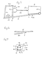
- the bins are usually produced with a external lip L (see Figure 5) around the top opening which may be used as a purchase point for hooking the bin at its front wall lip on to a bin inverting device as used on refuse collection vehicles for emptying the contents of the bin.
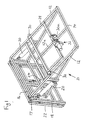
- the apparatus comprises a base frame 10 which is intended to be mounted on a vehicle or a wheeled trailer to allow transport to sites where bin cleaning is to be carried out.
- the base frame 10 has inclined parallel guide side rails 12 and central rail 12a which slope upwardly from lower bar 14 at the rear end of the base frame to upper bar 16 at its forward end.
- a bin tilting frame 18 is pivotally connected via pivots 17 to the base frame 10 at its forward end 16 for movement between a generally vertical loading position as shown in Figures 1 and 2 and a raised support position (see Figure 5) in which the tilting frame 18 is tilted at substantially the same angle as the guide rails 12, such tilting movement being effected by means of fluid-powered piston and cylinder assemblies 20 acting between the base frame 10 and the tilting frame 18.
- the tilting frame 18 slidably mounts a bin-lifting frame 22 for movement towards and away from the upper bar 16 under the control of flluid-powered piston and cylinder assembly 24.
- the lifting frame 22 is provided with a number of bin attachment projections 26 which form a "comb'' and are intended to engage the lip at the front of a bin and thereby attach a floor-standing bin to the lifting frame 22 and hence the tilting frame 18.
- the lifting frame 22 is movable from a lower position in which the hook projections are generally located below the level of the front wall lip when the bin is floor standing to a raised position in which it engages the lip and then raises the bin away from the floor to a level at which the top opening in the bin B is at substantially the same level as the upper bar 16. Where the bin is of the lidded variety, the lid will initially be opened before operating the tilting frame to move the bin to the tilted position.
- the lifting frame 22 is used to raise the bin in this manner when the tilting frame is in its bin-loading position so that when the bin has been lifted fully out of contact with the ground, it may then be tilted by raising the tilting frame into its support position.
- the bin opening 23 is presented towards the rear end of the base frame and the main axis of the bin is substantially parallel with the guide rails 12, 12a (as shown diagrammatically in Figure 5).
- a collection vessel (not shown) will be located at a suitable position to collect the used cleaning fluid for filtration and recycle. If desired, the tilting angle of the bin may be more pronounced than illustrated in Figure 5 in order to secure more effective draining of the bin.
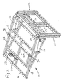
- a carriage 28 is mounted by means of guide rails 12, 12a, the carriage having wheels 30 which seat on guide rails 12 and a drive wheel 30a which engages the central guide rail 12a, the latter wheel being coupled to a drive motor/gear box unit 32 which is mounted on the carriage 28.
- the motor is reversible so that the carriage can be driven forwardly towards the upper bar 16 or rearwardly towards lower bar 14 (see arrows X in Figure 5).
- a cleaning unit 40 (see Figures 3 to 5) is mounted on the carriage 28 via posts 41 and forwardly extending arms 41a (see Figure 5).
- the cleaning unit comprises a reactangular main frame 42 mounting a pair of lances 44 through a gimbals-type arrangement comprising rectangular sub-frame 46 and generally U-shaped structures 48 each carrying a lance 44.
- the sub-frame 46 includes a pair of L-shaped arms 50 at each side thereof, the forwardly projecting ends of which are pivotally connected at 52 to arms 54 extending forwardly from the main frame 42 so that the sub-frame 46 can be oscillated angularly about a generally horizontal axis defined by pivots 52.
- Such angular oscillation is effected by means of a fluid-powered piston and cylinder assembly (not shown) acting between a pivot point afforded by bracket 56 on the main frame 42 and a pivot 58 located at the rear of the sub-frame 46.
- the U-shaped structures 48 are each pivotally connected at 60 to forwardly projecting arms 62 on the sub-frame 46 for angular oscillation about respective axes defined by the pivots 60, which axes are substantially perpendicular to the horizontal axis defined by pivots 52.
- Angular oscillation of the U-shaped structures 48 and the lances 44 is co-ordinated by links 66 which couple the U-shaped structures 48 and is effected by a fluid-powered piston and cylinder assembly (not shown) acting between the suitable points on the sub-frame 46 (see attachment point 68) and one of the U-shaped structures.
- Damping cylinders may also provided in conjunction with the piston and cylinder assemblies for effecting angular oscillation of the lances to smooth the oscillatory movement.
- the cleaning unit 40 is mounted on the carriage 28 so that the lances 44 project in the forward direction towards the tilting frame 18 for entry into the bin or bins B supported on the raised tilting frame 18 in use.
- the lances pass through the ''top'' opening 23 of the tilted bins and move towards the bases 25 thereof.
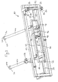
- Each lance 44 is provided with a nozzle assembly 74 at its forward end for discharging cleaning liquid and drying air, the liquid and air supplies to the lance and nozzle assemblies 74 being provided for example via flexible supply lines (not shown).
- the lance may comprise a steel tube along which the cleaning fluid is supplied and the air supply may be located externally of the tube, the central tube and the air supply lines being enclosed in a heavy duty plastics tube.
- each lance is movable in two mutually orthogonal degrees of freedom relative to the carriage 28 allowing control in such a way that the nozzle assemblies 74 execute a well-defined trajectory corresponding to the internal cross-section of the bins to be cleaned, e.g. as illustrated the path of travel 100 of each nozzle assembly 74 may be generally rectangular.
- the trajectory of nozzle travel may be contoured to the bin interior so that the nozzles travel in close proximity around the interior of the bins. It will be understood that such angular oscillation of the lances will take place during advance and retraction of the carriage 28 so that the nozzle assemblies 74 may pass over, in close proximity to, substantially the entire inner surface of the bins.
- the extent of angular oscillation is adjustable to cater for bins of different capacities and hence allow close proximity tracking of the inner bin wall surfaces by the nozzle assemblies 74.
- the oscillation of sub-frame 46 about the horizontal axis may be limited by upper and lower limit switches (not shown) operated by upper and lower discs 80 provided on spindle 82 which is mounted on the main frame 42 for vertical movement.
- the spindle 82 is provided with lateral projections 84 carrying adjustable bolts 86 which co-operate with a jockey wheel 88 mounted on one of the side arms 50.
- the spindle 82 is shown in Figures 3 and 4 in an inoperative position in which adjustment of the bolts is possible to allow the limits of oscillation to be varied; in use, the bolts 86 are positioned diametrically opposite to the location seen in Figures 3 and 4 so as to co-operate with the jockey wheel 88.
- the jockey wheel 88 moves into abutment with the upper and lower bolts 86 thereby displacing the assembly of disc/spindle assembly up or down and operating the associated limit switch which, in turn, causes the piston and cylinder assembly associated with sub-frame 46 to in readiness for movement of the sub-frame in the reverse direction at the appropriate time.
- Oscillation of the U-shaped structures 48 is controlled by a recessed cylinder 90 (see Figure 7) mounted between rearwardly projecting arms 98 of the sub-frame 66.
- the recess 92 in the cylinder receives a pin 94 carried by strap 96 secured to and extending between the links 66.
- the cylinder 90 is mounted for limited axial sliding movement between arms 98, the main axis 99 of the cylinder being substantially horizontal and the cylinder being angularly adjustable about that axis.
- the recess 92 progressively widens in the circumferential direction so that the degree of lost motion M between the pin 94 and the cylinder 90 is determined by the width of the groove 92 at the point of reception of the pin 94.
- the pin 94 travels to and fro from one side of the the recess 92 to the other and, on engaging each side, and shifts the cylinder in the direction of its axis to operate limit switches located adjacent each end of the cylinder 90 in readiness, at the appropriate time, for reverse operation of the piston and cylinder assembly which produces oscillation about the pivots 60.
- the pin 94 registers with the recess 92 at different width locations thereby increasing or reducing the degree of lost motion between the pin and cylinder and hence the varying the extent of movement that can occur before reversal of the associated piston and cylinder assembly takes place.
- two positions of pin 94 are illustrated. In the lower position, there is greater lost motion resulting in a large amplitude of angular oscillation.
- the nozzle assemblies 74 are illustrated diagrammatically in the drawings and may take various forms consistent with discharging cleaning fluid and drying air at the internal wall surfaces of the bins.
- the nozzle assemblies are supplied with suitable cleaning fluid (e.g. water containing additives such as detergent and/or biocide) and drying fluid (e.g. compressed air).
- suitable cleaning fluid e.g. water containing additives such as detergent and/or biocide
- drying fluid e.g. compressed air
- each nozzle assembly is arranged to discharge the cleaning fluid substantially forwardly from an outlet 102 at the end of the respective lance and. in this case, the attitude of the lances as they move along the interior of the bins towards the base of the bin is controlled in such a way that the lance points towards the side walls W so that cleaning fluid F impinges on the side wall surface at a glancing angle (see Figure 6) to enhance the cleaning effect.
- the drying air may also be discharged at the side walls of the bins in the same manner, e.g. from an outlet at the end of the lance.
- the drying air may be discharged forwardly of the lance and/or laterally of the lance.
- the nozzle assemblies may include laterally discharging outlets for the cleaning fluid and/or the drying air and in the case of the drying air, the laterally directed nozzles may be arranged to discharge at an angle towards the bin walls in the rearward direction so as to "drive" the used cleaning fluid towards the bin opening.
- lateral outlets 104 there may be four such lateral outlets 104 arranged equidistantly from each other around the axis of the lance (see Figure 4) and the arrangement may be such that the discharge of fluid (cleaning fluid and/or drying air) is co-ordinated with the position of the nozzle assembly so that the fluid is only discharged from only those lateral outlets that are directed towards the side wall surface undergoing cleaning and/or drying at any particular time during the cycle of operation.
- the lateral discharge outlets may be valve controlled, with the valves being opened only when the outlet is in close proximity and confronting relation with a respective side wall.
- a preferred feature of the invention resides in using the nozzle assemblies for effecting drying of the bin interiors in addition to cleaning.
- bin cleaning may be carried out during advance of the lances towards the base of the bins while bin drying is carried out during withdrawal.
- the nozzle assemblies are caused to track the inner wall surfaces of the bins in the manner described above.
- the drying air may be supplied in such a way that the pressurised air is effective to drive the residual liqud in the bin towards its open end as the lance moves in the direction of withdrawal from the bin. This may be achieved for example by appropriate orientation of the laterally discharging outlets.
- it is preferred to effect bin cleaning during the advance stroke of the lance and bin drying on the retraction stroke it will be appreciated that other possibilities exist. For instance, the lances may undergo two cycles of advance and retraction, bin cleaning being carried out during the first cycle and bin drying being carried during the second cycle.
- Another preferred feature of the invention is the use of a "rastering" type mode of operation of the lance adjacent the bottom of the bin so as to produce effective cleaning of the bin bottom.
- This is achieved by appropriate programming of the circuitry controlling of the lance oscillatory movements.
- the forward end of the lance may be caused to sweep to and fro between the extremities of its oscillation in one direction (e.g. side-to-side) and gradually incremented stepwise upwardly until the forward end of the lance reaches the uppermost edge of the bin bottom.
- the cleaning fluid will be discharged at the bin base.
- the lance may be oscillated back and forth for one or more traverses depending on the intensity of cleaning desired. The lance may then be withdrawn from the bin in the manner described previously. It will be appreciated that, instead of rastering the lance from side-to-side and incrementing it stepwise up or down, the rastering may be in the up-down direction and the stepwise incrementing may be side-to-side.
- Bin cleaning using apparatus as described above gives potential substantial savings in water usage and chemicals used for cleaning.
- a two-lance cleaner will employ a collective cleaning fluid flow rate of the order of 35 litres/minute (i.e. 17.5 litres per lance) and a discharge pressure of the order of 2000 psi.
- the apparatus may be made fully automatic so that the only action required on the part of the operator is to locate the bin or bins in position, fold back the bin lids, adjust controls (e.g. cylinder 90 and bolts 86) according to the capacities and cross-sectional dimensions of the bins to be cleaned and then operate a pushbutton or the like for initiating the cleaning and drying cycle.
- the cleaning and drying cycle then progresses automatically step by step culminating in withdrawal of the lances and return of the bins to their floor standing orientation by reverse operation of the tilting frame 18 and the lifting frame 22.
Landscapes
- Engineering & Computer Science (AREA)
- Mechanical Engineering (AREA)
- Cleaning By Liquid Or Steam (AREA)
- Preliminary Treatment Of Fibers (AREA)
- Feeding, Discharge, Calcimining, Fusing, And Gas-Generation Devices (AREA)
- Filtering Of Dispersed Particles In Gases (AREA)
- Cleaning In General (AREA)
- Electrical Discharge Machining, Electrochemical Machining, And Combined Machining (AREA)
- Camera Data Copying Or Recording (AREA)
Claims (24)
- Appareil de nettoyage de bennes comportant un support (18) servant à placer une benne (B) dans une position inclinée de manière à ce que le liquide puisse s'écouler de la benne par son ouverture supérieure (23), une lance de nettoyage (44) montée à mode de porte-à-faux sur une base (46, 48) pour le mouvement longitudinal en direction et hors d'une benne située sur le support, la lance étant munie, sur son extrémité libre ou de manière adjacente à celle-ci, d'un moyen d'évacuation du fluide (74) servant à évacuer le fluide de nettoyage (F) et étant montée sur la base de telle manière que le moyen d'évacuation du fluide soit mobile sur des plans essentiellement orthogonaux par rapport à la direction du mouvement longitudinal de la lance, et un moyen de commande pouvant être actionné pour produire de tels mouvements de la lance, caractérisé en ce que ledit appareil comprend en outre des moyens (80, 82, 84, 86, 88, 90, 92, 94) servant à produire un mouvement du type balayage de la lance.
- Appareil selon la revendication 1, dans lequel la lance est télescopique afin de produire ledit mouvement longitudinal en direction et hors de la benne.
- Appareil selon la revendication 1, dans lequel le support est disposé afin de placer une benne dans une position inclinée de manière à ce que le liquide puisse s'écouler de la benne par son ouverture supérieure, la base supporte un chariot (28) pour le mouvement en direction du support et dans le sens opposé, la lance de nettoyage étant montée à mode de porte-à-faux sur le chariot de manière à entrer et sortir d'une benne située sur le support tandis que le chariot est déplacé en direction du support et dans le sens opposé.
- Appareil selon l'une quelconque des revendications 1 à 3, dans lequel, lors de l'utilisation, le moyen de commande peut être actionné afin de déplacer le moyen d'évacuation du liquide en direction de la base de la benne et dans le sens opposé lorsque cette dernière est en appui sur le support et également sur lesdits plans essentiellement orthogonaux, moyennant quoi le moyen d'évacuation du fluide suit une trajectoire très proche des surfaces de la paroi latérale interne (40) de la benne tout en évacuant le fluide de nettoyage sur de telles surfaces.
- Appareil selon l'une quelconque des revendications 1 à 4, dans lequel la lance est montée de manière à pouvoir produire une oscillation angulaire afin de conférer au moyen d'évacuation du fluide au moins un degré de liberté sur lesdits plans essentiellement orthogonaux.
- Appareil selon l'une quelconque des revendications 1 à 4, dans lequel 1a lance est montée, de manière à pouvoir produire une oscillation angulaire, autour de deux axes mutuellement orthogonaux pour l'essentiel, afin de conférer au moyen d'évacuation du fluide deux degrés de liberté sur lesdits plans essentiellement orthogonaux.
- Appareil selon l'une quelconque des revendications 1 à 6, dans lequel le moyen de commande est réglable afin de permettre la modulation de l'extension du mouvement du moyen d'évacuation du fluide sur lesdits plans essentiellement orthogonaux en fonction des dimensions transversales des bennes à nettoyer.
- Appareil selon l'une quelconque des revendications 1 à 7, dans lequel le moyen de commande peut être actionné afin de déplacer le moyen d'évacuation du fluide sur lesdits plans essentiellement orthogonaux simultanément au mouvement du chariot dans au moins une direction par rapport au support.
- Appareil selon l'une quelconque des revendications 1 à 8, dans lequel le support est disposé de manière à loger plus d'une benne à la fois.
- Appareil selon la revendication 9, dans lequel on a prévu plusieurs lances destinées à être utilisées dans le nettoyage de bennes respectives, chaque lance étant munie de moyens d'évacuation du fluide respectifs.
- Appareil selon la revendication 10 comportant un chariot unique servant à supporter les lances.
- Appareil selon l'une quelconque des revendications 1 à 11, dans lequel le support comprend un châssis d'inclinaison de la benne (18) et un sous-châssis de levage de la benne (22).
- Appareil selon la revendication 12, dans lequel le châssis d'inclinaison peut être déplacé en angle par rapport à la base, autour d'un axe généralement perpendiculaire à la direction du mouvement du chariot (28).
- Appareil selon la revendication 12 ou 13, dans lequel le châssis de levage de la benne peut être coulissé par rapport au châssis d'inclinaison de la benne dans une direction généralement perpendiculaire à l'axe, autour duquel le châssis d'inclinaison est déplaçable en angle.
- Appareil selon l'une quelconque des revendications 1 à 14, dans lequel le moyen d'évacuation du fluide peut être actionné afin d'évacuer à la fois le fluide de nettoyage et le fluide de séchage en direction des surfaces internes de la benne en cours d'utilisation.
- Méthode de nettoyage d'une benne (23) comprenant :caractérisée ena) l'inclinaison de la benne dans une position telle que le liquide s'écoulera de la benne sous l'action de la force de gravité,b) l'avancement d'une lance de nettoyage (44) à travers l'ouverture de la benne (23) en direction de la base de la benne (25), la lance étant munie d'un moyen d'évacuation du fluide (74) sur son extrémité avant ou de manière adjacente à celle-ci,c) l'approvisionnement de la lance en fluide de nettoyage (?) pendant une telle avance,d) le déplacement de la lance sur le côté de ladite direction d'avance de telle sorte que le moyen d'évacuation du fluide suive une trajectoire du mouvement correspondant à la section transversale interne de la benne pendant l'avance en direction de ladite base, ete) la soumission de la lance à un mouvement de type balayage lorsque l'extrémité avant de la lance est adjacente à la base de la benne.
- Méthode selon la revendication 16, dans laquelle la lance est télescopique et est amenée à l'intérieur et à l'extérieur de la benne par l'extension et la rétraction de ses parties télescopiques.
- Méthode selon la revendication 16 ou 17, dans laquelle le fluide de nettoyage est évacué à un angle de réflexion en direction des parois latérales de la benne pendant l'avance de la lance.
- Méthode selon l'une quelconque des revendications 16 à 18 comprenant en outre le déplacement de la lance sur le côté de ladite direction d'avance de telle sorte que le moyen d'évacuation du fluide suive une trajectoire du mouvement correspondant à la section transversale interne de la benne pendant le retrait de la lance loin de ladite base de la benne.
- Méthode selon l'une quelconque des revendications 16 à 19, dans laquelle les étapes (a) à (e) et toute étape consécutive spécifiée dans l'une quelconque des revendications 21 à 24 sont automatiquement exécutées.
- Méthode selon l'une quelconque des revendications 16 à 20, comprenant en outre le réglage de l'extension du mouvement latéral de la lance en fonction de la zone transversale de la benne à nettoyer.
- Méthode selon l'une quelconque des revendications 16 à 21, dans laquelle plusieurs bennes à la fois sont nettoyées, chaque benne étant nettoyée au moyen d'une lance respective.
- Appareil selon l'une quelconque des revendications 1 à 15, dans lequel le mode de fonctionnement à balayage est produit lorsque l'extrémité avant de la lance est adjacente à la base de la benne.
- Méthode selon l'une quelconque des revendications 16 à 22 ou appareil selon la revendication 23, dans lesquels le mouvement de balayage comprend une traversée dans une direction transversale à l'axe de la lance et un mouvement par étapes dans une direction orthogonale par rapport à l'axe de la lance et à ladite direction.
Applications Claiming Priority (3)
| Application Number | Priority Date | Filing Date | Title |
|---|---|---|---|
| GB9929578A GB2357240B (en) | 1999-12-15 | 1999-12-15 | Bin cleaning apparatus |
| GB9929578 | 1999-12-15 | ||
| PCT/GB2000/004774 WO2001044081A1 (fr) | 1999-12-15 | 2000-12-14 | Appareil de lavage de poubelle |
Publications (2)
| Publication Number | Publication Date |
|---|---|
| EP1237802A1 EP1237802A1 (fr) | 2002-09-11 |
| EP1237802B1 true EP1237802B1 (fr) | 2004-09-22 |
Family
ID=10866318
Family Applications (1)
| Application Number | Title | Priority Date | Filing Date |
|---|---|---|---|
| EP00981487A Expired - Lifetime EP1237802B1 (fr) | 1999-12-15 | 2000-12-14 | Appareil de lavage de poubelle |
Country Status (8)
| Country | Link |
|---|---|
| US (1) | US6758225B2 (fr) |
| EP (1) | EP1237802B1 (fr) |
| AT (1) | ATE276944T1 (fr) |
| AU (1) | AU774874B2 (fr) |
| DE (1) | DE60014154T2 (fr) |
| ES (1) | ES2228637T3 (fr) |
| GB (1) | GB2357240B (fr) |
| WO (1) | WO2001044081A1 (fr) |
Families Citing this family (16)
| Publication number | Priority date | Publication date | Assignee | Title |
|---|---|---|---|---|
| GB0329073D0 (en) * | 2003-12-13 | 2004-01-14 | Covelec Ltd | Cleaning apparatus |
| FR2873600B1 (fr) * | 2004-07-29 | 2006-10-13 | Pronet Soc Par Actions Simplif | Installation de lavage de conteneurs. |
| US20080105761A1 (en) * | 2004-08-25 | 2008-05-08 | Blast N Clean Llc | Interior and exterior cleaning of waste carts and containers |
| US20080035176A1 (en) * | 2004-08-25 | 2008-02-14 | Byers Ernest F | Automated Cart and Container Cleaning System |
| US20080105474A1 (en) * | 2004-08-25 | 2008-05-08 | Blast N Clean Llc | Cart and container cleaning system with heated fluid |
| US20080110476A1 (en) * | 2004-08-25 | 2008-05-15 | Blast N Clean Llc | Container cleaning system using nozzles |
| US7398789B1 (en) | 2005-05-27 | 2008-07-15 | Sheila Herrera | Dumpster cleaning apparatus |
| FI122740B (fi) * | 2007-03-01 | 2012-06-15 | Ficote Oy | Laitteisto jäteastian pesemiseksi ja vastaava menetelmä |
| AU2008255188B2 (en) * | 2007-12-12 | 2014-03-20 | F.B. Technologies Pty Ltd | Bin cleaner |
| GB2458931A (en) * | 2008-04-03 | 2009-10-07 | Kwaku Antwi-Boasiako | A mobile bin washer |
| ITVR20080096A1 (it) * | 2008-09-01 | 2010-03-02 | Tecme Ete S R L | Apparecchiatura e procedimento per il lavaggio in automatico di cassonetti o similari |
| US20130291907A1 (en) * | 2012-05-07 | 2013-11-07 | Jim David Brozik | Spray Head Positioning Device |
| US11090701B2 (en) | 2017-02-14 | 2021-08-17 | Packline Technologies, Inc. | Bin cleaning systems and methods of use |
| US12485454B2 (en) | 2017-02-14 | 2025-12-02 | Packline Technologies, Inc. | Bin cleaning systems and methods of use |
| WO2018206997A1 (fr) * | 2017-05-10 | 2018-11-15 | Volvo Truck Corporation | Véhicule comprenant au moins une caméra et un système de lavage correspondant pour le nettoyage de la caméra |
| CN110949915A (zh) * | 2019-12-07 | 2020-04-03 | 盐城东方汽车广场投资发展有限公司 | 一种室外环保垃圾桶 |
Family Cites Families (12)
| Publication number | Priority date | Publication date | Assignee | Title |
|---|---|---|---|---|
| DE1924562C3 (de) * | 1969-05-14 | 1975-07-10 | Fahrzeugbau Haller Gmbh, 7000 Stuttgart | Mülltonnen-Spülwagen |
| DE2901599C2 (de) * | 1979-01-17 | 1985-02-21 | Fahrzeugbau Haller Gmbh, 7000 Stuttgart | Reinigungsvorrichtung für Müllbehälter o.dgl. |
| IT1195672B (it) * | 1983-10-07 | 1988-10-19 | Cristanini Adolfo | Apparecchiatura di lavaggio e disinfezione particolarmente per cassonetti stradali |
| US4694846A (en) * | 1986-09-09 | 1987-09-22 | Bouchard Roland D | Garbage truck with trash bin cleaning system |
| FR2645775B1 (fr) * | 1989-04-17 | 1991-07-12 | Plastic Omnium Cie | Vehicule de lavage de conteneurs, notamment de conteneurs pour la collecte mecanisee d'ordures menageres |
| FR2688203B1 (fr) * | 1992-03-06 | 1998-04-10 | Serge Seijido | Installation pour le nettoyage automatique de recipients tels que poubelles. |
| NL9301014A (nl) * | 1993-06-11 | 1995-01-02 | Geesink Bv | Inrichting voor het inzamelen van in afvalhouders aangeboden afval en het reinigen van geleegde afvalhouders. |
| US5560781A (en) * | 1995-05-08 | 1996-10-01 | The United States Of America As Represented By The Administrator Of The National Aeronautics And Space Administration | Process for non-contact removal of organic coatings from the surface of paintings |
| AU695793B2 (en) | 1996-09-09 | 1998-08-20 | Brett Frencham | Recycling pressure cleaning system |
| DE19647519A1 (de) * | 1996-11-16 | 1998-05-20 | Baier & Koeppel | Vorrichtung für oder an Müllfahrzeugen |
| GB2321843A (en) | 1997-02-04 | 1998-08-12 | Oliver Plunkett Mcdonald | Refuse bin cleaning apparatus |
| US6554008B2 (en) * | 2000-12-29 | 2003-04-29 | Dustin Dewey | Apparatus for and a method of cleaning a trash bin |
-
1999
- 1999-12-15 GB GB9929578A patent/GB2357240B/en not_active Expired - Fee Related
-
2000
- 2000-12-14 ES ES00981487T patent/ES2228637T3/es not_active Expired - Lifetime
- 2000-12-14 US US10/168,154 patent/US6758225B2/en not_active Expired - Fee Related
- 2000-12-14 AT AT00981487T patent/ATE276944T1/de not_active IP Right Cessation
- 2000-12-14 EP EP00981487A patent/EP1237802B1/fr not_active Expired - Lifetime
- 2000-12-14 AU AU18722/01A patent/AU774874B2/en not_active Ceased
- 2000-12-14 DE DE60014154T patent/DE60014154T2/de not_active Expired - Lifetime
- 2000-12-14 WO PCT/GB2000/004774 patent/WO2001044081A1/fr not_active Ceased
Also Published As
| Publication number | Publication date |
|---|---|
| DE60014154T2 (de) | 2005-09-22 |
| US20020189650A1 (en) | 2002-12-19 |
| AU774874B2 (en) | 2004-07-08 |
| GB2357240B (en) | 2003-12-17 |
| AU1872201A (en) | 2001-06-25 |
| WO2001044081A1 (fr) | 2001-06-21 |
| DE60014154D1 (de) | 2004-10-28 |
| US6758225B2 (en) | 2004-07-06 |
| GB2357240A (en) | 2001-06-20 |
| EP1237802A1 (fr) | 2002-09-11 |
| ATE276944T1 (de) | 2004-10-15 |
| ES2228637T3 (es) | 2005-04-16 |
| GB9929578D0 (en) | 2000-02-09 |
Similar Documents
| Publication | Publication Date | Title |
|---|---|---|
| EP1237802B1 (fr) | Appareil de lavage de poubelle | |
| US3881950A (en) | Multiple drum washing apparatus for vehicles | |
| US7398789B1 (en) | Dumpster cleaning apparatus | |
| US4835811A (en) | Brushing and washing machine | |
| EP0559541B1 (fr) | Installation pour le nettoyage de récipients tels que poubelles | |
| EP0667192B1 (fr) | Appareil de nettoyage de conteneurs | |
| CN112092709A (zh) | 一种矿用自卸车车斗 | |
| DK200001009A (da) | Spuleindretning til brug i et apparat til rengøring af containere | |
| CN115610882B (zh) | 一种高精度垃圾转运处理设备 | |
| US6672317B2 (en) | Cleaning device for rotationally symmetrical bodies | |
| JP2620552B2 (ja) | ごみを収集する路面掃除機 | |
| GB2283409A (en) | Washing refuse bins | |
| EP0578317B1 (fr) | Procédé et dispositif pour vider et nettoyer des poubelles et véhicule à ordures equipé d'un tel dispositif | |
| EP0256699A2 (fr) | Dispositif de nettoyage de l'intérieur d'un bâti | |
| CN218946715U (zh) | 一种道路桥梁围栏维修焊接装置 | |
| CN217615521U (zh) | 一种锯片加工用喷涂装置 | |
| NL1023248C2 (nl) | Inrichting voor het opnemen en in een in hoofdzaak omgekeerde toestand in een ruimte van een voertuig plaatsen van afvalhouders, alsmede een wasinrichting en een afvalinzamelingsvoertuig. | |
| AU728688B2 (en) | Bin washer | |
| EP0202513B1 (fr) | Machine à laver avec des brosses | |
| SU1183208A1 (ru) | Способ промывки внутренней поверхности емкости | |
| JPH08500999A (ja) | フロア・トリートメント装置 | |
| IE910346A1 (en) | Container for use in a vacuum cleaner | |
| CN221159937U (zh) | 一种便于收放料的喷砂装置 | |
| CN223491635U (zh) | 一种大型陶坛清洗生产线 | |
| US20250206524A1 (en) | Waste bin cleaning truck |
Legal Events
| Date | Code | Title | Description |
|---|---|---|---|
| PUAI | Public reference made under article 153(3) epc to a published international application that has entered the european phase |
Free format text: ORIGINAL CODE: 0009012 |
|
| 17P | Request for examination filed |
Effective date: 20020615 |
|
| AK | Designated contracting states |
Kind code of ref document: A1 Designated state(s): AT BE CH CY DE DK ES FI FR GB GR IE IT LI LU MC NL PT SE TR |
|
| AX | Request for extension of the european patent |
Free format text: AL;LT;LV;MK;RO;SI |
|
| 17Q | First examination report despatched |
Effective date: 20021015 |
|
| GRAP | Despatch of communication of intention to grant a patent |
Free format text: ORIGINAL CODE: EPIDOSNIGR1 |
|
| GRAS | Grant fee paid |
Free format text: ORIGINAL CODE: EPIDOSNIGR3 |
|
| GRAA | (expected) grant |
Free format text: ORIGINAL CODE: 0009210 |
|
| AK | Designated contracting states |
Kind code of ref document: B1 Designated state(s): AT BE CH CY DE DK ES FI FR GB GR IE IT LI LU MC NL PT SE TR |
|
| PG25 | Lapsed in a contracting state [announced via postgrant information from national office to epo] |
Ref country code: TR Free format text: LAPSE BECAUSE OF FAILURE TO SUBMIT A TRANSLATION OF THE DESCRIPTION OR TO PAY THE FEE WITHIN THE PRESCRIBED TIME-LIMIT Effective date: 20040922 Ref country code: CY Free format text: LAPSE BECAUSE OF FAILURE TO SUBMIT A TRANSLATION OF THE DESCRIPTION OR TO PAY THE FEE WITHIN THE PRESCRIBED TIME-LIMIT Effective date: 20040922 Ref country code: AT Free format text: LAPSE BECAUSE OF FAILURE TO SUBMIT A TRANSLATION OF THE DESCRIPTION OR TO PAY THE FEE WITHIN THE PRESCRIBED TIME-LIMIT Effective date: 20040922 Ref country code: CH Free format text: LAPSE BECAUSE OF FAILURE TO SUBMIT A TRANSLATION OF THE DESCRIPTION OR TO PAY THE FEE WITHIN THE PRESCRIBED TIME-LIMIT Effective date: 20040922 Ref country code: FI Free format text: LAPSE BECAUSE OF FAILURE TO SUBMIT A TRANSLATION OF THE DESCRIPTION OR TO PAY THE FEE WITHIN THE PRESCRIBED TIME-LIMIT Effective date: 20040922 Ref country code: LI Free format text: LAPSE BECAUSE OF FAILURE TO SUBMIT A TRANSLATION OF THE DESCRIPTION OR TO PAY THE FEE WITHIN THE PRESCRIBED TIME-LIMIT Effective date: 20040922 |
|
| REG | Reference to a national code |
Ref country code: GB Ref legal event code: FG4D |
|
| REG | Reference to a national code |
Ref country code: CH Ref legal event code: EP |
|
| REG | Reference to a national code |
Ref country code: IE Ref legal event code: FG4D |
|
| REF | Corresponds to: |
Ref document number: 60014154 Country of ref document: DE Date of ref document: 20041028 Kind code of ref document: P |
|
| PG25 | Lapsed in a contracting state [announced via postgrant information from national office to epo] |
Ref country code: LU Free format text: LAPSE BECAUSE OF NON-PAYMENT OF DUE FEES Effective date: 20041214 |
|
| PG25 | Lapsed in a contracting state [announced via postgrant information from national office to epo] |
Ref country code: SE Free format text: LAPSE BECAUSE OF FAILURE TO SUBMIT A TRANSLATION OF THE DESCRIPTION OR TO PAY THE FEE WITHIN THE PRESCRIBED TIME-LIMIT Effective date: 20041222 Ref country code: GR Free format text: LAPSE BECAUSE OF FAILURE TO SUBMIT A TRANSLATION OF THE DESCRIPTION OR TO PAY THE FEE WITHIN THE PRESCRIBED TIME-LIMIT Effective date: 20041222 Ref country code: DK Free format text: LAPSE BECAUSE OF FAILURE TO SUBMIT A TRANSLATION OF THE DESCRIPTION OR TO PAY THE FEE WITHIN THE PRESCRIBED TIME-LIMIT Effective date: 20041222 |
|
| LTIE | Lt: invalidation of european patent or patent extension |
Effective date: 20040922 |
|
| REG | Reference to a national code |
Ref country code: CH Ref legal event code: PL |
|
| REG | Reference to a national code |
Ref country code: ES Ref legal event code: FG2A Ref document number: 2228637 Country of ref document: ES Kind code of ref document: T3 |
|
| PLBE | No opposition filed within time limit |
Free format text: ORIGINAL CODE: 0009261 |
|
| STAA | Information on the status of an ep patent application or granted ep patent |
Free format text: STATUS: NO OPPOSITION FILED WITHIN TIME LIMIT |
|
| ET | Fr: translation filed | ||
| 26N | No opposition filed |
Effective date: 20050623 |
|
| PGFP | Annual fee paid to national office [announced via postgrant information from national office to epo] |
Ref country code: MC Payment date: 20061221 Year of fee payment: 7 |
|
| PG25 | Lapsed in a contracting state [announced via postgrant information from national office to epo] |
Ref country code: PT Free format text: LAPSE BECAUSE OF NON-PAYMENT OF DUE FEES Effective date: 20050222 |
|
| PG25 | Lapsed in a contracting state [announced via postgrant information from national office to epo] |
Ref country code: MC Free format text: LAPSE BECAUSE OF NON-PAYMENT OF DUE FEES Effective date: 20071231 |
|
| PGFP | Annual fee paid to national office [announced via postgrant information from national office to epo] |
Ref country code: IE Payment date: 20131230 Year of fee payment: 14 Ref country code: DE Payment date: 20131220 Year of fee payment: 14 |
|
| PGFP | Annual fee paid to national office [announced via postgrant information from national office to epo] |
Ref country code: NL Payment date: 20131219 Year of fee payment: 14 Ref country code: IT Payment date: 20131223 Year of fee payment: 14 Ref country code: ES Payment date: 20131226 Year of fee payment: 14 |
|
| PGFP | Annual fee paid to national office [announced via postgrant information from national office to epo] |
Ref country code: BE Payment date: 20131219 Year of fee payment: 14 |
|
| PGFP | Annual fee paid to national office [announced via postgrant information from national office to epo] |
Ref country code: FR Payment date: 20131220 Year of fee payment: 14 |
|
| PG25 | Lapsed in a contracting state [announced via postgrant information from national office to epo] |
Ref country code: BE Free format text: LAPSE BECAUSE OF NON-PAYMENT OF DUE FEES Effective date: 20141231 |
|
| REG | Reference to a national code |
Ref country code: DE Ref legal event code: R119 Ref document number: 60014154 Country of ref document: DE |
|
| REG | Reference to a national code |
Ref country code: NL Ref legal event code: V1 Effective date: 20150701 |
|
| REG | Reference to a national code |
Ref country code: NL Ref legal event code: V1 Effective date: 20150701 |
|
| REG | Reference to a national code |
Ref country code: IE Ref legal event code: MM4A |
|
| REG | Reference to a national code |
Ref country code: FR Ref legal event code: ST Effective date: 20150831 |
|
| PG25 | Lapsed in a contracting state [announced via postgrant information from national office to epo] |
Ref country code: NL Free format text: LAPSE BECAUSE OF NON-PAYMENT OF DUE FEES Effective date: 20150701 |
|
| PG25 | Lapsed in a contracting state [announced via postgrant information from national office to epo] |
Ref country code: DE Free format text: LAPSE BECAUSE OF NON-PAYMENT OF DUE FEES Effective date: 20150701 Ref country code: IE Free format text: LAPSE BECAUSE OF NON-PAYMENT OF DUE FEES Effective date: 20141214 |
|
| PG25 | Lapsed in a contracting state [announced via postgrant information from national office to epo] |
Ref country code: FR Free format text: LAPSE BECAUSE OF NON-PAYMENT OF DUE FEES Effective date: 20141231 |
|
| PG25 | Lapsed in a contracting state [announced via postgrant information from national office to epo] |
Ref country code: IT Free format text: LAPSE BECAUSE OF NON-PAYMENT OF DUE FEES Effective date: 20141214 |
|
| REG | Reference to a national code |
Ref country code: ES Ref legal event code: FD2A Effective date: 20160128 |
|
| PG25 | Lapsed in a contracting state [announced via postgrant information from national office to epo] |
Ref country code: ES Free format text: LAPSE BECAUSE OF NON-PAYMENT OF DUE FEES Effective date: 20141215 |
|
| PGFP | Annual fee paid to national office [announced via postgrant information from national office to epo] |
Ref country code: GB Payment date: 20161214 Year of fee payment: 17 |
|
| GBPC | Gb: european patent ceased through non-payment of renewal fee |
Effective date: 20171214 |
|
| PG25 | Lapsed in a contracting state [announced via postgrant information from national office to epo] |
Ref country code: GB Free format text: LAPSE BECAUSE OF NON-PAYMENT OF DUE FEES Effective date: 20171214 |