EP1237782B1 - Light emitting diode assembly for use as an aircraft position light - Google Patents
Light emitting diode assembly for use as an aircraft position light Download PDFInfo
- Publication number
- EP1237782B1 EP1237782B1 EP00983904A EP00983904A EP1237782B1 EP 1237782 B1 EP1237782 B1 EP 1237782B1 EP 00983904 A EP00983904 A EP 00983904A EP 00983904 A EP00983904 A EP 00983904A EP 1237782 B1 EP1237782 B1 EP 1237782B1
- Authority
- EP
- European Patent Office
- Prior art keywords
- circuit board
- leds
- circuit boards
- light
- led
- Prior art date
- Legal status (The legal status is an assumption and is not a legal conclusion. Google has not performed a legal analysis and makes no representation as to the accuracy of the status listed.)
- Expired - Lifetime
Links
- 230000003287 optical effect Effects 0.000 claims description 29
- 238000004891 communication Methods 0.000 claims description 9
- 230000001154 acute effect Effects 0.000 claims description 7
- 238000009826 distribution Methods 0.000 description 13
- 229910052736 halogen Inorganic materials 0.000 description 12
- 238000006073 displacement reaction Methods 0.000 description 10
- 230000008901 benefit Effects 0.000 description 9
- 239000011521 glass Substances 0.000 description 8
- 125000005843 halogen group Chemical group 0.000 description 7
- 238000003384 imaging method Methods 0.000 description 7
- 230000004297 night vision Effects 0.000 description 7
- 238000013461 design Methods 0.000 description 6
- 150000002367 halogens Chemical class 0.000 description 5
- 238000012423 maintenance Methods 0.000 description 5
- 238000004519 manufacturing process Methods 0.000 description 5
- 230000003595 spectral effect Effects 0.000 description 5
- 239000000463 material Substances 0.000 description 4
- 238000002834 transmittance Methods 0.000 description 4
- 230000000694 effects Effects 0.000 description 3
- 239000004033 plastic Substances 0.000 description 3
- 239000013598 vector Substances 0.000 description 3
- 230000005540 biological transmission Effects 0.000 description 2
- 230000015572 biosynthetic process Effects 0.000 description 2
- 230000008859 change Effects 0.000 description 2
- 238000010276 construction Methods 0.000 description 2
- 230000014509 gene expression Effects 0.000 description 2
- 238000005286 illumination Methods 0.000 description 2
- 230000002045 lasting effect Effects 0.000 description 2
- 239000003550 marker Substances 0.000 description 2
- 238000012986 modification Methods 0.000 description 2
- 230000004048 modification Effects 0.000 description 2
- 230000001105 regulatory effect Effects 0.000 description 2
- 239000004065 semiconductor Substances 0.000 description 2
- 238000001228 spectrum Methods 0.000 description 2
- 229910005540 GaP Inorganic materials 0.000 description 1
- 240000003380 Passiflora rubra Species 0.000 description 1
- 241001223864 Sphyraena barracuda Species 0.000 description 1
- 239000000853 adhesive Substances 0.000 description 1
- 230000001070 adhesive effect Effects 0.000 description 1
- AJGDITRVXRPLBY-UHFFFAOYSA-N aluminum indium Chemical compound [Al].[In] AJGDITRVXRPLBY-UHFFFAOYSA-N 0.000 description 1
- 239000003086 colorant Substances 0.000 description 1
- 239000002131 composite material Substances 0.000 description 1
- 238000004590 computer program Methods 0.000 description 1
- 230000002950 deficient Effects 0.000 description 1
- 230000001934 delay Effects 0.000 description 1
- 230000002939 deleterious effect Effects 0.000 description 1
- 238000002474 experimental method Methods 0.000 description 1
- 230000002349 favourable effect Effects 0.000 description 1
- HZXMRANICFIONG-UHFFFAOYSA-N gallium phosphide Chemical compound [Ga]#P HZXMRANICFIONG-UHFFFAOYSA-N 0.000 description 1
- 229910052738 indium Inorganic materials 0.000 description 1
- APFVFJFRJDLVQX-UHFFFAOYSA-N indium atom Chemical compound [In] APFVFJFRJDLVQX-UHFFFAOYSA-N 0.000 description 1
- 238000009434 installation Methods 0.000 description 1
- 238000000034 method Methods 0.000 description 1
- 239000002991 molded plastic Substances 0.000 description 1
- 150000004767 nitrides Chemical class 0.000 description 1
- 230000009467 reduction Effects 0.000 description 1
- 230000006903 response to temperature Effects 0.000 description 1
- 230000035945 sensitivity Effects 0.000 description 1
- 230000007480 spreading Effects 0.000 description 1
- 238000003892 spreading Methods 0.000 description 1
- 238000012360 testing method Methods 0.000 description 1
Images

Classifications
-
- B—PERFORMING OPERATIONS; TRANSPORTING
- B64—AIRCRAFT; AVIATION; COSMONAUTICS
- B64D—EQUIPMENT FOR FITTING IN OR TO AIRCRAFT; FLIGHT SUITS; PARACHUTES; ARRANGEMENT OR MOUNTING OF POWER PLANTS OR PROPULSION TRANSMISSIONS IN AIRCRAFT
- B64D47/00—Equipment not otherwise provided for
- B64D47/02—Arrangements or adaptations of signal or lighting devices
- B64D47/06—Arrangements or adaptations of signal or lighting devices for indicating aircraft presence
-
- F—MECHANICAL ENGINEERING; LIGHTING; HEATING; WEAPONS; BLASTING
- F21—LIGHTING
- F21V—FUNCTIONAL FEATURES OR DETAILS OF LIGHTING DEVICES OR SYSTEMS THEREOF; STRUCTURAL COMBINATIONS OF LIGHTING DEVICES WITH OTHER ARTICLES, NOT OTHERWISE PROVIDED FOR
- F21V5/00—Refractors for light sources
- F21V5/04—Refractors for light sources of lens shape
-
- B—PERFORMING OPERATIONS; TRANSPORTING
- B64—AIRCRAFT; AVIATION; COSMONAUTICS
- B64D—EQUIPMENT FOR FITTING IN OR TO AIRCRAFT; FLIGHT SUITS; PARACHUTES; ARRANGEMENT OR MOUNTING OF POWER PLANTS OR PROPULSION TRANSMISSIONS IN AIRCRAFT
- B64D2203/00—Aircraft or airfield lights using LEDs
-
- F—MECHANICAL ENGINEERING; LIGHTING; HEATING; WEAPONS; BLASTING
- F21—LIGHTING
- F21W—INDEXING SCHEME ASSOCIATED WITH SUBCLASSES F21K, F21L, F21S and F21V, RELATING TO USES OR APPLICATIONS OF LIGHTING DEVICES OR SYSTEMS
- F21W2107/00—Use or application of lighting devices on or in particular types of vehicles
- F21W2107/30—Use or application of lighting devices on or in particular types of vehicles for aircraft
-
- F—MECHANICAL ENGINEERING; LIGHTING; HEATING; WEAPONS; BLASTING
- F21—LIGHTING
- F21Y—INDEXING SCHEME ASSOCIATED WITH SUBCLASSES F21K, F21L, F21S and F21V, RELATING TO THE FORM OR THE KIND OF THE LIGHT SOURCES OR OF THE COLOUR OF THE LIGHT EMITTED
- F21Y2115/00—Light-generating elements of semiconductor light sources
- F21Y2115/10—Light-emitting diodes [LED]
-
- H—ELECTRICITY
- H05—ELECTRIC TECHNIQUES NOT OTHERWISE PROVIDED FOR
- H05K—PRINTED CIRCUITS; CASINGS OR CONSTRUCTIONAL DETAILS OF ELECTRIC APPARATUS; MANUFACTURE OF ASSEMBLAGES OF ELECTRICAL COMPONENTS
- H05K1/00—Printed circuits
- H05K1/02—Details
- H05K1/14—Structural association of two or more printed circuits
-
- H—ELECTRICITY
- H05—ELECTRIC TECHNIQUES NOT OTHERWISE PROVIDED FOR
- H05K—PRINTED CIRCUITS; CASINGS OR CONSTRUCTIONAL DETAILS OF ELECTRIC APPARATUS; MANUFACTURE OF ASSEMBLAGES OF ELECTRICAL COMPONENTS
- H05K1/00—Printed circuits
- H05K1/18—Printed circuits structurally associated with non-printed electric components
-
- Y—GENERAL TAGGING OF NEW TECHNOLOGICAL DEVELOPMENTS; GENERAL TAGGING OF CROSS-SECTIONAL TECHNOLOGIES SPANNING OVER SEVERAL SECTIONS OF THE IPC; TECHNICAL SUBJECTS COVERED BY FORMER USPC CROSS-REFERENCE ART COLLECTIONS [XRACs] AND DIGESTS
- Y10—TECHNICAL SUBJECTS COVERED BY FORMER USPC
- Y10S—TECHNICAL SUBJECTS COVERED BY FORMER USPC CROSS-REFERENCE ART COLLECTIONS [XRACs] AND DIGESTS
- Y10S362/00—Illumination
- Y10S362/80—Light emitting diode
Definitions
- This invention relates generally to an aircraft position light, and more specifically, to an aircraft position light formed by a light emitting diode assembly.
- airplanes are required to have left and right position lights consisting of a red light and a green light spaced laterally as far apart as practical, and installed on the airplane such that, when the airplane is in normal flying position, the red light is on the left side of the airplane and the green light is on the right side of the airplane. Additionally, airplanes must have a rear position light which is a white light mounted as far aft as practical on the tail or on each wingtip ofthe airplane.
- the FAA within a position light's intended field of coverage, the FAA establishes minimum intensities only, and outside the intended field of coverage, the FAA establishes maximum intensities. In this manner, an airplane's attitude and position can easily be determined from multiple viewing angles while at the same time insuring that the lights are not too intense beyond the position lights' field of coverage to confuse or overpower other pilots, aircraft lights, and ground-based entities.
- each position light In addition to horizontal and vertical light intensity requirements, Federal Aviation Regulations also require each position light to be of a specific color based upon International Commission on Illumination chromaticity coordinates. Federal Aviation Regulations use these chromaticity coordinates to define a particular range of chromaticities or colors suitable for position lights, defined as aviation red, aviation green, and aviation white. The left position light must be aviation red, the right position light must be aviation green, and the rear position light must be aviation white.
- Light covers are typically made of colored glass, and are placed in front of the light source: However, the use of these covers in flight conditions and with incandescent or halogen light sources can result in undesired consequences. For example, the transmittance of red and green glass covers is only about 20 percent. This results in the use of a relatively high powered lamp to meet light intensity requirements. High powered incandescent and halogen light sources emit a large amount of heat, which can shatter light covers made of glass. Furthermore, light covers can change color and transmittance with temperature, so that light intensity and color may fluctuate outside of specified Federal Aviation Regulation requirements in response to temperature variations.
- position lights must operate each time an aircraft is operating at night and because the lights can be difficult to access, especially on large commercial aircraft, it is advantageous for position lights to have long life and to perform reliably.
- position lights which use conventional incandescent and halogen lamps can typically burn out after 1000 to 2000 hours of operation. This can occur at an inopportune time, such as in-flight or during a short layover on a runway.
- the lamps inside these position lights are frequently replaced while the airplane is on the tarmac. This frequent lamp replacement represents a high burden to airplane operators, maintenance crews, air traffic control, and any passenger or cargo on the airplane.
- incandescent and halogen position lights each require about 150-200 watts of power to produce intensity to meet FAA lighting requirements with suitable margin and redundancy.
- 100-200 watt position lights are typically employed to provide twice the light intensity required under Federal Aviation Regulations. With multiple position lights on each airplane, this high power requirement contributes to a large power load, which is undesirable because of the limitations of the generators on an aircraft.
- the heavy weight of incandescent and halogen position lights and light covers make the lights difficult to install, and add to undesirable weight to the aircraft.
- (red and white) incandescent and halogen position lights emit light having a broad spectrum and relatively high amount of infrared energy, making the lights interfere with night vision imaging systems (NVIS), such as employed in military and night rescue applications.
- NVIS night vision imaging systems
- the Japanese patent application no. 07201209 provides an auxiliary lighting part, comprising a linear light source arranged in a dummy part of a duct cover to compose a part of a rear combination lamp of a car.
- the light source comprises a linear light source having a plurality of LEDs positioned on a printed board which is mounted on a housing. The plurality of LEDs are covered by a cover lens.
- the dummy cover constructs part of a rear combination lamp as an auxiliary illumination part.
- US-5,567,036 provides a clearance and side marker lamp, especially suited for use with truck/trailer combinations.
- the lamp is provided with LEDs mounted to a plurality of circuit boards.
- the circuit boards are mounted at predetermined angles relative to each other for directing light in at least three directions.
- a lens is provided in front of the LEDs and includes a series of prism optics for spreading the light emitted from the LEDs into an arc of up to 180 degrees.
- US-5,388,035-A provides a vehicular marker lamp including three LEDs located within a cup-shaped housing having a flat, transparent front wall or lens.
- the ribs are angled differently so that the beam from each diode is spread to a different extent.
- the width of the output beam is about 30° in the vertical plane and 90° in the horizontal plane.
- the present invention utilizes an assembly of light emitting diodes (LEDs) to produce a position light which meets Federal Aviation Regulation lighting requirements while lasting longer than conventional incandescent and halogen position lights, and being relatively lighter, cheaper, and requiring less power than conventional position lights.
- LEDs light emitting diodes
- Colored LEDs may be chosen to comply with Federal Aviation Regulations lighting color requirements, obviating the need for colored light covers.
- the narrow spectral distribution of LEDs results in the additional benefit that the position light of the present invention will interfere less with night vision imaging systems, as compared with conventional incandescent lamp based position lights.
- the invention includes three embodiments as defined in independent claims 1, 10 and 16.
- a light emitting diode (LED) assembly for use as an aircraft position light includes a first plurality of circuit boards in electrical communication with a base circuit board. Each circuit board of the first plurality of circuit boards is parallel to every.other circuit board of the first plurality of circuit boards. In addition, each of the first plurality of circuit boards is disposed at the same acute angle relative to the base circuit board.
- the LED assembly also includes a second plurality of circuit boards in electrical communication with the base circuit board. Each circuit board of the second plurality of circuit boards is disposed at an angle to every other circuit board of the second plurality of circuit boards. As such, and wherein the second plurality of circuit boards form a fan-shaped structure.
- the LED assembly includes a plurality of light emitting diodes electrically mounted to said first plurality of circuit boards and to said second plurality of circuit boards.
- Each circuit board of the first plurality of circuit boards and the second plurality of circuit boards in the LED assembly can be identical to every other circuit board of the first plurality of circuit boards and the second plurality of circuit boards, to facilitate manufacturing of the assembly, and to lower the costs associated with manufacture and maintenance.
- the plurality ofLEDs can include rows of LEDs, where each row ofLEDs is electrically mounted to a single circuit board of the first plurality of circuit boards and the second plurality of circuit boards.
- Each circuit board in turn, can be electrically and mechanically connected to the base circuit board at a first edge thereof.
- the LEDs are, in turn, connected to the circuit board at a second edge, substantially opposite the first edge.
- each circuit board of the first plurality of circuit boards and the second plurality of circuit boards can define an axis extending between the first and second edges of the circuit board that is disposed in a plane that is perpendicular to the base circuit board.
- at least one LED of the plurality of LEDs can be connected to the circuit board so that the LED is aligned with the axis.
- at least one LED may be located on the circuit board so that the LED is angled relative to the portions that cooperate to define an arched edge.
- the second edge of each circuit board can include multiple edges. LEDs can abut the multiple edge portions so that the LEDs are oriented in different directions. For example, a number ofLEDs could abut a center edge portion so that the LEDs are parallel to vertical axis defined by the circuit board.
- LEDs can be mounted upon other edge portions that are angled relative to the center edge portion. For example, LEDs can be mounted at angles of ⁇ 12° and ⁇ 24° relative to the axis defined by the circuit board. Since the orientation of the LEDs is generally derived from the angle of the multiple edge portions with respect to the axis defined by the circuit board, the proper angular orientation of the LEDs may be ensured by placement of the LEDs directly adjacent the edge portions of the circuit board.
- the manner in which the LEDs and circuit boards can be oriented on the base circuit board can be determined such that the position light meets and exceeds the lighting requirements of Federal Aviation Regulations.
- software operating on a computer may be utilized to determine the light intensity at all points in space of a position light according to the present invention.
- the software may do so by being programmed with conventional mathematical expressions which add known characteristics of light emission from multiple LEDs to produce a three dimensional plot of light intensity for a given assembly of LEDs. Therefore, through trial and error, the most effective embodiments of the present invention can be determined.
- the LEDs can be chosen to meet the specific color requirements of Federal Aviation Regulations so that a colored light cover is not required to be placed in front of the position light. Furthermore, the LEDs chosen can have a narrow spectral distribution such that they interfere less with night vision imaging systems than conventional position lights.
- the LED assembly also includes a glass or optical plastic cover (lens) located adjacent the plurality of LEDs, where the optical cover includes a first optical section and a second optical section.
- the first optical section can include a first plurality of faces located on a side of the optical cover opposite the plurality of LEDs, wherein each face of the first plurality of faces is parallel to each other face of the first plurality of faces, and wherein each face of the first plurality of faces is positioned at the same acute angle relative to the base circuit board.
- the second optical section can include a second plurality of faces located on a side of the optical cover opposite the plurality of LEDs, wherein each face of the second plurality of faces is positioned at a different angle relative to the base circuit board than each other face of the second plurality of faces.
- each face of the first plurality of faces and each face of the second plurality of faces can correspond to a respective LED of the plurality of LEDs.
- each face of the first plurality of faces and each face of the second plurality of faces can correspond to at least one LED of the plurality of LEDs.
- each of the plurality of LEDs located within the position light assembly can be identical
- a forward position light according to an aspect of the present invention will first be introduced, including an assembly of LEDs mounted in various directions, followed by a more detailed description of the individual components of the position light.
- the use of various types of LEDs, including their orientation, effect on the orientation of components of the position light, and benefits, will be described.
- a software program will be described which allows a design engineer to tailor the forward position light to meet predetermined requirements.
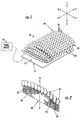
- FIG. 1 shows a forward position light 10 in accordance with an embodiment of the present invention.
- the forward position light 10 includes a base circuit board 15 and a plurality of circuit boards that are electrically and mechanically connected to the base circuit board 15.
- the forward position light 10 also includes a plurality of light emitting diodes (LEDs) 25 electrically and mechanically mounted upon each circuit board 20.
- the forward position light 10 includes a power source 12 in electrical communication with the base circuit board 15 , which, in turn, provides power to the LEDs 25 which emit light in a multitude of directions relative to the base circuit board 15.
- the forward position light 10 can be mounted to an airplane by bolts, clamps, screws, adhesives, or by other suitable well known means.
- FIG. 5A One location of a forward position light 10, on an airplane wing, is illustrated in FIG. 5A.
- the plurality of circuit boards can be connected to the base circuit board 15 at a variety of angles, so that at least one circuit board 20 is positioned at an acute angle relative to a surface 17 of the base circuit board 15.
- the plurality of circuit boards can be mounted directly to the base circuit board 15 using any suitable technique known to those of skill in the art.
- the plurality of circuit boards can be mounted to the base circuit board 15 using a mounting structure, as illustrated in FIG. 4.
- the purpose of angling or slanting at least one circuit board 20 and, more preferably, a plurality of circuit boards, with respect to the surface 17 is to achieve vertical (z-axis) light distribution in the directions of the y-axis and the -y-axis (i.e., about the ⁇ x-axis in the z-axis direction), as shown in FIG. 1.
- the plurality of LEDs 25 connected to each individual circuit board 20 may be oriented at different angles to achieve vertical (z-axis) dispersal of light in the x-axis and the -x-axis directions (i.e., about the ⁇ y-axis in the z-axis direction).
- the LEDs 25 can be mounted on a circuit board 20 in a fan-like manner so that at least one LED 23 points toward the x-axis, and at least one LED 24 points toward the -x-axis. Therefore, through the combined orientations of the circuit boards and LEDs 25 located on each board 20, the forward position light 10 can emit light in multiple directions in the 3-dimensional space defined by the x, y and z-axes. In the embodiment of FIG. 1, 156 LEDs are mounted on 13 circuit boards, so that the LEDs are at 30 different angular orientations, a configuration which will be described in more detail with reference to FIG. 4, below. However, the position light 10 can include different numbers of circuit boards and different numbers of LEDs, if so desired.
- One advantage of the position light 10 according to the present invention is that minimum position light intensities can be achieved with a light requiring less power than conventional incandescent and halogen position lights.
- the embodiment shown in FIG. 1, utilizing 156 conventional LEDs and 13 circuit boards requires approximately 20 watts of power, as compared to conventional light sources requiring approximately 200 watts of power to meet FAA position light intensity requirements with suitable margin and redundancy. Such a decrease in power is favorable to aircraft design, where efficient power management is critical.
- the current through LEDs should be regulated via current regulating integrated circuit chips so that voltage variation will not affect the light intensity of the position light 10 or the current through the LEDs. This current regulation may be required because LEDs utilize semiconductors that have large fluctuations in current based upon small changes in voltage, which can have deleterious effects on LED semiconductor material.
- the position light 10, and its individual components will be described in more detail with respect to FIGS. 2-5.
- FIG. 2 shows a perspective view of a circuit board 20 of the position light 10 shown in FIG. 1, in accordance with an embodiment of the present invention.
- each individual circuit board 20 of the position light 10 can be identical. Therefore, the circuit board 20 of FIG. 2 may be representative of any circuit board of the plurality of circuit boards included in the position light 10 .
- each circuit board 20 can be unique in both shape and construction. Nonetheless, the use of identical circuit boards is preferred because identical circuit boards minimize the cost of manufacturing and maintaining the position light 10 , and simplify its assembly and maintenance. Furthermore, the use of identical circuit boards can simplify the replacement of defective boards.
- the circuit board 20 can include a first edge 40 for electrical and mechanical connection with the base circuit board 15 , and a second edge 44 substantially opposite the first edge 40 .
- the circuit board can define an axis 35 that extends between the first and second edges 40 , 44 .
- the axis 35 is disposed within a plane that is substantially perpendicular to the upper surface 17 of the base circuit board 15 once the circuit board is mounted thereon.
- a plurality of LEDs 25 are electrically and mechanically connected to the second edge 44 of the circuit board 20 . In the embodiment of FIG. 2, the LEDs 25 are connected to the second edge 44 in a row formation.
- the second edge 44 of the circuit board 20 typically includes a plurality of edge portions, as will be described in more detail with reference to FIG. 3A.
- the LEDs 25 are preferably mounted along each of the edge portions.
- the LEDs 25 can also be mounted to the circuit board 20 in an alternative manner.
- the LEDs 25 may be located on either one or both sides of the circuit boards proximate to the second edge 44.
- the LEDs 25 can emit light generally away from the surface 17 of the base circuit board 15. Because the second edge of the circuit board can be arched, as in the embodiment of FIG. 2, the LEDs 25 may emit light in a plurality of directions when mounted thereon. Additionally, because the LEDs 25 are mounted such that the LEDs 25 are oriented at different vertical displacements, side emissions off the LEDs 25 are not blocked by adjacent LEDs 25 , which helps meet the vertical angle light intensity requirements, as discussed below.
- the LEDs 25 are electrically connected 30 to the circuit board 20 by LED leads 27, which are illustrated with phantom lines.
- the LED leads 27 may be wire bonds or the like that provide jumper-type connection to the circuit board 20, or the LED leads 27 may be traces disposed on or within the circuit board 20.
- the circuit board 20 may include conductive terminals to which the LEDs 25 may be connected.
- the circuit board 20 can comprise a printed circuit board, a printed wiring board or any other board suitable to electrically and mechanically receive a plurality of LEDs 25 , and be electrically and mechanically connected to base circuit board 15 such that the LEDs 25 may be powered by a power source 12 (see FIG. 1).
- the base circuit board 15 and the plurality of circuit boards mounted thereupon typically include a network of electrical traces that effectively fan out the current provided by the power source 12 to the LEDs 25 .
- Fig. 3A shows a front view of the circuit board 20 of FIG. 2, including the angular orientations of the LEDs 25 with respect to the axis 35 defined by the circuit board 20.
- the second edge 44 of the circuit board 20 can include multiple edge portions 45-49 that form an arched edge.
- the LEDs 25 abut the multiple edge portions 45-49 so that the LEDs 25 are oriented in five (5) different directions.
- four (4) LEDs 25 abut a center edge portion 45 of the second edge 44 so that the four LEDs are parallel to the axis 35; two (2) LEDs 25 abut a first middle edge portion 46 of the second edge 44 so that the two LEDs 25 are angled at 12° with respect to the axis 35; and two (2) LEDs 25 abut a first outer edge portion 48 of the second edge 44 so that the LEDs 25 are angled at 24° with respect to the axis 35.
- two (2) LEDs 25 are mounted to a second middle edge portion 47 of the second edge 44 , at -12° with respect to the axis 35, and two (2) LEDs 25 are mounted to second outer edge portion 49 , at -24° with respect to the axis 35.
- LEDs 25 oriented at specific angles (i.e., 0°, ⁇ 12°, or ⁇ 24°) from the axis 35 of the circuit board 20 derive their angular orientation from the angle of the multiple edge portions 45-49 with respect to the axis 35 .
- the middle edge portions 46, 47 are angled at ⁇ 12 degrees, respectively, and outer edges 48 and 49 are angled at ⁇ 24 degrees, respectively, to the center edge portion 45.
- specific angular orientations of the LEDs 25 may be achieved by placement of the LEDs 25 directly adjacent the multiple edge portions 45-49 at the second edge 44 of the circuit board 20 .
- the LED assembly can have multiple configurations to produce multiple angular orientations of the LEDs 25 .
- the circuit board 20 may include more edge portions, such as a respective edge portion for each individual LED, or may comprise a smooth and continuous arched edge upon which the LEDs may be mounted.
- the second edge 44 of the circuit board 20 may only include only a single, linear edge, and the angular orientations of the LEDs 25 may be created by the manner in which the LEDs 25 are mounted to the circuit board 20 .
- one or more LEDs 25 may be angled with respect to a linear edge by changing the length of an LED lead 27.
- the number of LEDs 25 mounted on the circuit board 20 may vary according to the number of circuit boards included in the position light 10 , as well as the types of LEDs 25 and the intensity of the LEDs 25, as will be discussed below.
- FIG. 3B shows a front view of the circuit board shown in FIG. 2, in accordance with an embodiment of the invention, including light distribution vectors. Because the second edge of the circuit board can be arched, as discussed above, the LEDs 25 may emit light in a plurality of directions. The light distribution of three LEDs is illustrated in FIG. 3B with light distribution vectors. It will be appreciated that because the LEDs 25 are at different vertical displacements due to the arched second edge 44 of the circuit board 20, side emissions off the LEDs 25 are not blocked by adjacent LEDs 25, which helps the position light 10 meet Federal Aviation vertical angle light intensity requirements.
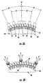
- FIG. 4 shows a side view of the position light 10 of FIG. 1 in accordance with an embodiment of the present invention, including an mounting structure which mounts the plurality of circuit boards to the base circuit board 15 .
- the mounting structure may be integral to the base circuit board, or may be separate from the base circuit board 15 and attached to the base circuit board 15 after each are independently constructed.
- the mounting structure can be constructed of any suitable material strong enough to hold the circuit boards in a steady position relative to the base circuit board 15, and which will not interfere with the operation of the position light.
- the mounting structure may be formed of molded plastic. It should be appreciated that the mounting structure may facilitate the mounting of circuit boards at specific angles. It should also be appreciated that the mounting structure must allow the circuit boards to be electrically connected to the base circuit board 15.
- FIG. 4 shows 13 circuit boards electrically and mechanically mounted to the base circuit board 15.
- the individual circuit boards 20 of the position light 10 are identical although mounted at different angles with respect to the surface 17 of the base circuit board 15.
- the specific orientations of each circuit board 20 and the respective LEDs 25 thereon were chosen in order to achieve and surpass the light intensity required by Federal Aviation Regulations when the position light 10 is fixed to an airplane wingtip.
- the position light 10 includes a first plurality of circuit boards 50 and a second plurality of circuit boards 55, together comprising the plurality of circuit boards of the position light 10.
- Each circuit board 20 of the first plurality of circuit boards 50 is parallel to each other circuit board 20 of the first plurality of circuit boards 50. Additionally, each circuit board 20 of the first plurality of circuit boards 50 is positioned at an acute angle to the surface 17 of the base circuit board 15. On the contrary, each circuit board 20 of the second plurality of circuit boards 55 is angled relative to each other such that the second plurality of circuit boards 55 forms a fan-shaped structure.
- each circuit board 20 comprising the first plurality of circuit boards 50 and second plurality of circuit boards 55 is illustrated with respect to a Direction of Flight axis.
- the Direction of Flight (DOF) axis indicates the DOF of an airplane, and identifies the attitude of the position light 10 in relation to the DOF of an airplane when the light is mounted to an airplane wingtip.
- an axis representing the 110° outboard angle which is the maximum horizontal angle from the DOF axis requiring a minimum light intensity under Federal Aviation Regulations. This 110° angle can be more easily appreciated with reference to FIG. 5A, which shows a graphical representation of the 110° horizontal angle with respect to a position light 10 .
- each circuit board 20 of the first plurality of circuit boards 50 is mounted to the base circuit board 15 such that its axis 35 (shown in FIGS. 2 and 3) is at an angle ⁇ of 7° from the DOF axis.
- the vertical axis of the five individual circuit boards 20 are angled at 25°, 41°, 59°, 77° and 95° with respect to the DOF axis:
- FIG. 5A shows a graphical representation of the horizontal requirements with respect to a forward position light on the left wing of an airplane and a table listing the light intensity requirements for all horizontal positions of such a light. For example, at a horizontal angle between 0-10°, Federal Aviation Requirements require a minimum light intensity of forty (40) candela. Thirty (30) candela of light intensity is required between 10-20 degrees, and five (5) candela is required at angles between 20-110 degrees from the DOF.
- FIG. 5B shows the Federal Aviation Regulation forward position light intensity requirements for vertical angles, and a graphical representation of the requirements with respect to a forward position light on the left wing of an airplane.
- the requirements for light intensity at vertical angles are symmetrical both above and below the position of the wing.
- light intensity requirements are equal for corresponding locations on the x-axis and -x axis.
- each board 20 included in the first plurality of circuit boards 50 and the second plurality of circuit boards 55 may be varied.
- the preferred orientation of the circuit boards in FIG 4., and the number of LEDs used was selected to achieve twice the Federal Aviation Requirements for light intensity at any given vertical and horizontal displacement.
- additional angular displacements may be employed that still meet or achieve the minimum lighting requirements under Federal Aviation Regulations for position lights.
- an alternative embodiment might include a plurality of circuit boards, where none of the circuit boards are parallel to each other.
- circuit boards comprising the second plurality of circuit boards 55 in the embodiment of FIG. 4 may include any number of circuit boards that are oriented at angles of, for example, between 1° and 89°.
- Preferred orientations of the individual LEDs 25 and circuit boards 20 can be determined by calculating LED positions using known performance characteristics of multiple LEDs placed in close proximity. First, it is known that when multiple LEDs are combined, their individual light patterns add together (i.e., superposition applies). Furthermore, if multiple LEDs with the same pattern of light are aimed in the same direction, the shape of the intensity or apotization pattern remains the same as that pattern emitted by an individual LED, but the magnitude of the light increases. Given these known phenomena, and Federal Aviation Regulation horizontal and vertical light intensity requirements, preferred orientations of the LEDs 25 and circuit boards 20 according to the present invention can be determined. First, however, the use of various types of LEDs, and the effects of their including their orientation, will be discussed.
- the types of LEDs 25 comprising the position light 10 may vary.
- T 1-3/4 High Intensity 30° LEDs manufactured by Hewlett Packard Corporation, San Jose, Ca.
- the type ofLEDs 25 may effect the number of LEDs and orientation and number of circuit boards 20 required to meet minimum light intensity requirements.
- an LED used in the present invention can be a T 1-3/4 style LED, measuring 4.8 mm (0.190 inches) in diameter, which generally produces a narrow pattern of light; a HP Superflux (trademark of Hewlett Packard (HP) Corporation) LED, producing a broader light pattern; or a HP Barracuda LED, producing a batwing lighting pattern, which is most intense at specific angles off the LED's vertical axis.
- the exterior lens shape of the LED, the shape of the LED's internal reflector, the index of refraction of the encapsulating material surrounding the anode, cathode and die of the LED, and the location of the die relative to the lens and/or internal reflector dictate the intensity pattern of the LED device.
- each circuit board shown in FIG. 2 is preferably exchangeable with any other circuit board in the position light
- the LEDs 25 utilized throughout the position light 10 are preferably the same type, although this is not required.
- each LED selected for an individual position light 10 should comply with Federal Aviation Regulation color requirements, so that need for a colored light cover is obviated.
- Red, green and white LEDs are commercially available from Hewlett Packard and other LED suppliers which meet the required chromaticity requirements.
- an aviation green LED made by Hewlett Packard (San Jose, Ca.), is constructed of InGaN (Indium gallum nitride), and an aviation red LED is constructed of AlInGaP (Aluminum Indium Gallium Phosphide).
- the colored light cover can be eliminated, potentially resulting in less weight and cost, and overcoming difficulties resulting from the change of transmittance and light intensity which results when light covers are subjected to variations in temperatures, as in conventional position lights. It will be appreciated by those of skill in the art that a clear glass cover will still be required so that the LEDs will be protected and the wing will be aerodynamic.
- LEDs in the present invention over incandescent and halogen position lights is the narrow spectrum of light generated by LEDs.
- LEDs are inherently more night vision imaging system compatible because they produce zero or very little radiance in the 450-930 nanometer range, compared with incandescent or filtered incandescent sources having much broader spectrums (incandescent sources produce energy up to and above 50,000 nm).
- night vision imaging systems NVIS have a spectral sensitivity range of 450 to 930 nanometers, LEDs do cause as much reduction in NVIS gain or interfere as much with their operation. NVIS can be utilized by military and night rescue operations, as well as many other applications.
- the above-described embodiments of the present invention were determined using a software program operating on a computer.
- the software program written specifically for this application using conventional computer software language (Mathcad 6.0, manufactured by Mathsoft) uses known mathematical expressions to allow a user to specify the intensity patterns and angular locations of hundreds of LEDs for the purpose of predicting the intensity pattern of a complete LED assembly.
- the software can compute the aggregate intensity pattern of the LED assembly and compare it at all angular locations with the Federal Aviation Regulation required intensity for a forward position light.
- the software program allows a design engineer to specify the intensity pattern of any known LEDs being considered for a position light design. Based upon information provided from each LED manufacturer, the intensity of light emitted by each LED for any angular displacement can be entered. Next, a the design engineer can experiment with combinations of different LED types, with different intensities at various angular displacements, and can simulate the location of hundreds of LEDs at different horizontal and vertical angles. The software can add the light intensities of all the LEDs to produce a composite intensity pattern for the complete assembly of LEDs. In this manner, a complete analysis of a LED assembly can be made without building and testing prototypes.
- the assembly ofLEDs produces a position light which meets Federal Aviation Regulation lighting requirements while lasting longer than conventional incandescent and halogen position lights, and being relatively lighter, cheaper, and requiring less power than conventional position lights. Furthermore, because colored LEDs may be chosen to comply with Federal Aviation Regulations lighting color requirements, colored light covers are not required. Moreover, the narrow spectral distribution of LEDs results in the additional benefit that the position light of the present invention does not interfere as nearly as much with the operation of night vision imaging systems, as compared with conventional position lights.
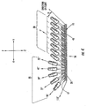
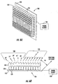
- FIG. 6A shows a perspective view of a position light 100 in accordance with another embodiment of the present invention
- FIG. 6B shows a side view of the position light 100
- a plurality LEDs 125 may be mounted directly to the base circuit board 150, in a manner well known in the art, and arranged in a grid or other formation, so that the LEDs 125 are oriented generally perpendicular to the base circuit board 150 .
- a clear light cover or lens 130 may be placed over or located directly adjacent the LEDs 125, where the clear light cover 130 can contain one or more glass or optical plastic sections which enable the LEDs 125 to emit light in a multitude of directions.
- the clear optical light cover 130 directs light from the LEDs 125 in a multitude of directions and at the appropriate angles to achieve the required light distribution and intensity of required by Federal Aviation Regulations. It will be appreciated by those of skill in the art that the base circuit board is electrically connected to a power source, and that the LEDs 125 are in electrical communication with the base circuit board 150 so that the LEDs 125 can be powered.
- the clear optical light cover of this embodiment is made of optical plastic, but in an alternative embodiment the optical cover 130 could also be manufactured from glass or other suitable material.
- the transmission properties of the optical light cover 130 are specular (transparent) but in an alternative embodiment the optical light cover 130 could be specular or diffuse (translucent) or a combination of both in order to achieve the Federal Aviation Regulation requirements for light intensity of a position light.
- the clear optical light cover 130 is designed to use refraction in some regions and internal reflection in other regions to achieve the desired angular deflection of light originating from the LEDs 125.
- An alternative embodiment might include more than one circuit board 100 and optical light cover 130 aimed in the same direction or at different angles in relatively close proximity to one another or separated by some distance if necessary to facilitate a particular aircraft installation.
- the clear optical light cover 130 can comprise a section 135 and a second section 138.
- the first section 135 can include a plurality of faces located on a side of the optical light cover 130 opposite the plurality ofLEDs 125 .
- Each of the plurality of faces in the first section 135 are parallel to each other, and are positioned at the same acute angle relative to the base circuit board 150 . These faces are illustrated as angled to refract light at 7° horizontally with respect to the direction of flight (DOF) axis.
- the second section 138 can also include a plurality of faces located on a side of the optical light cover 130 opposite the plurality of LEDs 125 .
- each face of the second section 138 is positioned at a different (horizontal and vertical) angle relative to the base circuit board 150 than each other face of the second section 138 .
- These faces are illustrated as angled to refract or internally reflect light horizontally at 25°, 41°, 59°, 77°, and 95° with respect to the DOF axis. The angles of these faces also cause the light to refract light in the vertical axis at -24°,-12°, 0°, 12° and 24°.
- each of the plurality of LEDs 125 located within the position light 100 can be identical. Furthermore, each face of the first plurality of faces and each face of the second plurality of faces can correspond to a respective LED of the plurality of LEDs 125. Alternatively, each face of the first plurality of faces and each face of the second plurality of faces can correspond to more than one LED of the plurality of LEDs 125 .
- the embodiment of FIGs. 6A and 6B can be implemented using any number and type ofLEDs, and can utilize.a light cover having any number of sections oriented in a multitude of directions and angles.
- the orientations of the sections, and the number of LED, as well as LED types can be determined using a computer program, as described above.
- the optical transmittance properties of the light cover 130 can be specular (transparent), diffuse (translucent), or a combination of specular and diffuse.
- the light cover 130 can have regions which are specular for directing the light from an LED with minimal scattering, and other regions which are translucent for scattering the light from an individual LED or collection of LEDs.
- regions which are specular for directing the light from an LED with minimal scattering and other regions which are translucent for scattering the light from an individual LED or collection of LEDs.
- diffuse transmission could be used to distribute light in the extreme vertical angular locations where the FAA requires minimal intensity.
- One advantage of the position light illustrated in FIGs. 6A and 6B is that the position light 100 may cost less to manufacture and maintain than the position light 10 described with respect to FIGs.
Landscapes
- Engineering & Computer Science (AREA)
- Aviation & Aerospace Engineering (AREA)
- General Engineering & Computer Science (AREA)
- Fastening Of Light Sources Or Lamp Holders (AREA)
- Non-Portable Lighting Devices Or Systems Thereof (AREA)
- Led Device Packages (AREA)
Description
Furthermore, like the first embodiment, each of the plurality of LEDs located within the position light assembly can be identical
Claims (19)
- A light emitting diode (LED) assembly for use as an aircraft position light, comprising:a base circuit board (15);a first plurality of circuit boards (20) in electrical communication with the base circuit board (15), wherein each circuit board (20) of the first plurality of circuit boards is parallel to each other circuit board of the first plurality of circuit boards, and wherein each circuit board is positioned at the same acute angle relative to the base circuit board (15);a second plurality of circuit boards (55) in electrical communication with the base circuit board (15), wherein each circuit board of (20) the second plurality of circuit boards is positioned at a different angle relative to the base circuit board such that the second plurality of circuit boards form a fan-shaped structure; anda plurality of light emitting diodes (LEDs) (25) electrically mounted to said first plurality of circuit boards (50) and to said second plurality of circuit boards (55).
- The LED assembly of claim 1, wherein each circuit board (20) of the first plurality of circuit boards (50) and the second plurality of circuit boards (55) is identical to every other circuit board of the first plurality of circuit boards and the second plurality of circuit boards.
- The LED assembly of claim 1 or 2, wherein the plurality of LEDs (25) mounted to said first plurality of circuit boards (50) and to said second plurality of circuit boards (55) are identical.
- The LED assembly of claim 1, 2 or 3, wherein the plurality of LEDs (25) mounted to a respective one of said first plurality of circuit boards (50) and said second plurality of circuit boards (55) form a fan-like pattern so that at least one LED of the plurality of LEDs is disposed at an angle relative to another LED of the plurality of LEDs.
- The LED assembly of any of claims 1-4, wherein the plurality of LEDs comprise rows of LEDs, and wherein each row of LEDs is electrically mounted to a respective circuit board of the first plurality of circuit boards and the second plurality of circuit boards.
- The LED assembly of any of claims 1-5, wherein each circuit board (20) of the first plurality of circuit boards (50) and the second plurality of circuit boards (55) has opposed first and second edges, wherein each circuit board is mounted to the base circuit board (15) at the first edge (40), and wherein the plurality of LEDs (25) are mounted to said each circuit board at the second edge (44).
- The LED assembly of claim 6, wherein each circuit board of the first plurality of circuit boards (50) and the second plurality of circuit boards (55) defines an axis that lies in a plane that is substantially perpendicular to the base circuit board (15) and that extends from the first edge (40) of said each circuit board to the opposed second edge (44), and wherein at least one LED of the plurality of LEDs mounted to said each circuit board is aligned with the axis.
- The LED assembly of claim 6 or 7, wherein the second edge of each circuit board includes a plurality of edge portions (45-49)that cooperate to define an arched edge.
- The LED assembly of claim 8, wherein the plurality of LEDs (25) are mounted to the first plurality of circuit boards (50) and the second plurality of circuit boards (55) such that the LEDs abut each of the plurality of edge portions (45-49).
- A light emitting diode (LED) assembly for use as an aircraft position light, comprising:a base circuit board (15);a plurality of circuit boards (20) having opposed first and second edges, wherein each circuit board is in electrical and mechanical connection with the base circuit board (15) along the first edge (40) of the circuit board, and a plurality of light emitting diodes (LEDs) in electrical communication with each circuit board and abutting the second edge (44) of the circuit board, and wherein the second edge of each circuit board includes a plurality of edge portions (45-49) that cooperate to define an arched edge.
- The LED assembly of claim 10, wherein at least one of the plurality of circuit boards is angled relative to another one of the plurality of circuit boards.
- The LED assembly of claim 10 or 11, wherein at least one of the plurality of LEDs (25) is angled with respect to another one of the plurality of LEDs.
- The LED assembly of claim 10, 11 or 12 wherein each circuit board (20) of the plurality of circuit boards is identical.
- The LED assembly of any of claims 10-13, wherein each LED (25) of the plurality of LEDs is identical.
- The LED assembly of claim 13, wherein the plurality of LEDs are mounted to each circuit board such that at least one LED abuts each of the plurality of edge portions.
- A light emitting diode (LED) assembly for use as an aircraft position light, comprising:a base circuit board (150);a plurality of light emitting diodes (LEDs) in electrical communication with said base circuit board;an optical cover (130) located adjacent said plurality of LEDs, wherein the optical cover comprises a first optical section (135) and a second optical section (138), wherein:said first optical section (135) comprises a first plurality of faces located on a side of the optical cover opposite said plurality of LEDs, wherein each face of said first plurality of faces is parallel to each other face of said first plurality of faces, and wherein each face of said first plurality of faces is positioned at the same acute angle relative to the base circuit board (15);said second optical section (138) comprising a second plurality of faces located on a side of the optical cover opposite said plurality of LEDs, wherein each face of said second plurality of faces is positioned at a different angle relative to the base circuit board than each other face of said second plurality of faces.
- The LED assembly of claim 16, wherein each of the plurality of LEDs (125) are identical.
- The LED assembly of claim 17, wherein each face of the first plurality of faces and each face of the second plurality of faces correspond to a respective LED of the plurality of LEDs (125).
- The LED assembly of claim 17 or 18, wherein each face of the first plurality of faces and each face of the second plurality of faces correspond to at least one LED of the plurality of LEDs (125).
Applications Claiming Priority (3)
| Application Number | Priority Date | Filing Date | Title |
|---|---|---|---|
| US459550 | 1999-12-13 | ||
| US09/459,550 US6244728B1 (en) | 1999-12-13 | 1999-12-13 | Light emitting diode assembly for use as an aircraft position light |
| PCT/US2000/032945 WO2001042083A1 (en) | 1999-12-13 | 2000-12-04 | Light emitting diode assembly for use as an aircraft position light |
Publications (2)
| Publication Number | Publication Date |
|---|---|
| EP1237782A1 EP1237782A1 (en) | 2002-09-11 |
| EP1237782B1 true EP1237782B1 (en) | 2005-04-27 |
Family
ID=23825249
Family Applications (1)
| Application Number | Title | Priority Date | Filing Date |
|---|---|---|---|
| EP00983904A Expired - Lifetime EP1237782B1 (en) | 1999-12-13 | 2000-12-04 | Light emitting diode assembly for use as an aircraft position light |
Country Status (6)
| Country | Link |
|---|---|
| US (1) | US6244728B1 (en) |
| EP (1) | EP1237782B1 (en) |
| JP (1) | JP4553540B2 (en) |
| AU (1) | AU2060201A (en) |
| DE (1) | DE60019796T2 (en) |
| WO (1) | WO2001042083A1 (en) |
Families Citing this family (95)
| Publication number | Priority date | Publication date | Assignee | Title |
|---|---|---|---|---|
| GB2330679B (en) | 1997-10-21 | 2002-04-24 | 911 Emergency Products Inc | Warning signal light |
| FR2775250B1 (en) * | 1998-02-24 | 2000-05-05 | Wilco International Sarl | AIRCRAFT LIGHTING MEDIA COMPATIBLE WITH A NIGHT VISION SYSTEM |
| US6462669B1 (en) | 1999-04-06 | 2002-10-08 | E. P . Survivors Llc | Replaceable LED modules |
| WO2000074973A1 (en) * | 1999-06-08 | 2000-12-14 | 911 Emergency Products, Inc. | Rotational led reflector |
| US6705745B1 (en) * | 1999-06-08 | 2004-03-16 | 911Ep, Inc. | Rotational led reflector |
| US6547410B1 (en) * | 2000-07-28 | 2003-04-15 | 911 Emergency Products, Inc. | LED alley/take-down light |
| TW457732B (en) * | 1999-08-27 | 2001-10-01 | Lumileds Lighting Bv | Luminaire, optical element and method of illuminating an object |
| US6712486B1 (en) * | 1999-10-19 | 2004-03-30 | Permlight Products, Inc. | Mounting arrangement for light emitting diodes |
| US6354714B1 (en) * | 2000-04-04 | 2002-03-12 | Michael Rhodes | Embedded led lighting system |
| US6431728B1 (en) * | 2000-07-05 | 2002-08-13 | Whelen Engineering Company, Inc. | Multi-array LED warning lights |
| DE10034767A1 (en) * | 2000-07-18 | 2002-05-02 | Hella Kg Hueck & Co | lamp |
| US7055994B2 (en) * | 2000-09-19 | 2006-06-06 | L-3 Communications Corporation | Light source assembly and methods for aircraft external lighting |
| US6559777B1 (en) | 2000-09-19 | 2003-05-06 | L-3 Communications Corporation | Dual mode light source for aircraft external lighting |
| WO2003068599A1 (en) * | 2000-09-19 | 2003-08-21 | L-3 Communications Corporation | Light source assembly for vehicle external lighting |
| US6618123B2 (en) * | 2000-10-20 | 2003-09-09 | Matsushita Electric Industrial Co., Ltd. | Range-finder, three-dimensional measuring method and light source apparatus |
| US20020170134A1 (en) * | 2001-05-21 | 2002-11-21 | Martin John H. | Scraper with swiveling T-handle |
| US6578986B2 (en) * | 2001-06-29 | 2003-06-17 | Permlight Products, Inc. | Modular mounting arrangement and method for light emitting diodes |
| US6717525B1 (en) * | 2001-08-02 | 2004-04-06 | The United States Of America As Represented By The Secretary Of The Navy | Tactical vectoring equipment |
| US6669357B2 (en) | 2001-09-26 | 2003-12-30 | The Boeing Company | Surface illumination system of an aircraft and like vehicles |
| US6525668B1 (en) * | 2001-10-10 | 2003-02-25 | Twr Lighting, Inc. | LED array warning light system |
| FR2838087B1 (en) * | 2002-04-04 | 2004-11-19 | Tavernier Serge De | LUMINOUS SIGNALING DEVICE FOR COLLISION PREVENTION |
| GB0211214D0 (en) * | 2002-05-16 | 2002-06-26 | Oxley Dev Co Ltd | Light source |
| US7040786B2 (en) * | 2002-10-04 | 2006-05-09 | Goodrich Hella Aerospace Lighting Systems Gmbh | Anticollision light for aircraft |
| EP1405789A1 (en) * | 2002-10-04 | 2004-04-07 | Goodrich Hella Aerospace Lighting Systems GmbH | Anti-collision light for aircraft |
| US20080037257A1 (en) * | 2002-12-11 | 2008-02-14 | Charles Bolta | Light emitting diode (L.E.D.) lighting fixtures with emergency back-up and scotopic enhancement |
| AU2003296485A1 (en) * | 2002-12-11 | 2004-06-30 | Charles Bolta | Light emitting diode (l.e.d.) lighting fixtures with emergency back-up and scotopic enhancement |
| US7278766B2 (en) * | 2003-04-04 | 2007-10-09 | Honeywell International Inc. | LED based light guide for dual mode aircraft formation lighting |
| TW576614U (en) * | 2003-06-30 | 2004-02-11 | Yi-Chen Tang | Low-voltage driven high-brightness LED |
| US20050036312A1 (en) * | 2003-08-14 | 2005-02-17 | Para Light Electronics Co., Ltd. | Light emitting diode based lighting device |
| US20050052118A1 (en) * | 2003-09-05 | 2005-03-10 | Shuit-Tong Lee | Organic electroluminescent devices formed with rare-earth metal containing cathode |
| US7102172B2 (en) * | 2003-10-09 | 2006-09-05 | Permlight Products, Inc. | LED luminaire |
| DE10349869A1 (en) * | 2003-10-25 | 2005-06-16 | Eads Deutschland Gmbh | System and method for protecting means of transport against IR-guided missiles |
| US6935595B2 (en) * | 2003-10-28 | 2005-08-30 | Honeywell International Inc. | Pilot director light utilizing light emitting diode (LED) technology |
| WO2005054745A1 (en) * | 2003-12-05 | 2005-06-16 | Auto Concepts Australia Pty Ltd | A lamp assembly |
| US20050151708A1 (en) * | 2004-01-12 | 2005-07-14 | Farmer Ronald E. | LED module with uniform LED brightness |
| JP3845092B2 (en) * | 2004-01-16 | 2006-11-15 | 株式会社シマノ | Bicycle lighting device |
| US7645053B2 (en) * | 2005-01-13 | 2010-01-12 | Honeywell International Inc. | Rotationally symmetrical LED-based anti-collision light for aircraft |
| US7414546B2 (en) * | 2004-07-08 | 2008-08-19 | Honeywell International Inc. | White anti-collision light utilizing light-emitting diode (LED) technology |
| US7165863B1 (en) | 2004-09-23 | 2007-01-23 | Pricilla G. Thomas | Illumination system |
| US7377669B2 (en) * | 2005-03-28 | 2008-05-27 | U.S. Led, Ltd. | LED module and system of LED modules with integral branch connectors |
| US7918591B2 (en) * | 2005-05-13 | 2011-04-05 | Permlight Products, Inc. | LED-based luminaire |
| CN103925521A (en) | 2005-12-21 | 2014-07-16 | 科锐公司 | Lighting device |
| JP2007178408A (en) * | 2005-12-28 | 2007-07-12 | Olympus Corp | Reactor vessel and analyzer |
| JP5148510B2 (en) * | 2006-01-27 | 2013-02-20 | 藤森工業株式会社 | Packaging bag with spout |
| JP2007220572A (en) * | 2006-02-20 | 2007-08-30 | Stanley Electric Co Ltd | Lighting device |
| WO2007142946A2 (en) | 2006-05-31 | 2007-12-13 | Cree Led Lighting Solutions, Inc. | Lighting device and method of lighting |
| US8201977B2 (en) * | 2008-10-07 | 2012-06-19 | Electraled, Inc. | LED illuminated member within a refrigerated display case |
| US8985795B2 (en) | 2006-06-30 | 2015-03-24 | Electraled, Inc. | Elongated LED lighting fixture |
| US8235539B2 (en) * | 2006-06-30 | 2012-08-07 | Electraled, Inc. | Elongated LED lighting fixture |
| US8956005B2 (en) * | 2006-06-30 | 2015-02-17 | Electraled, Inc. | Low-profile elongated LED light fixture |
| US7665862B2 (en) * | 2006-09-12 | 2010-02-23 | Cree, Inc. | LED lighting fixture |
| US7766508B2 (en) * | 2006-09-12 | 2010-08-03 | Cree, Inc. | LED lighting fixture |
| US20080094857A1 (en) * | 2006-10-20 | 2008-04-24 | Smith Robert B | LED light bulb |
| CN201007456Y (en) * | 2007-03-06 | 2008-01-16 | 欧阳杰 | Lighting device with LED as light source |
| US7824070B2 (en) * | 2007-03-22 | 2010-11-02 | Cree, Inc. | LED lighting fixture |
| US7663506B2 (en) * | 2007-07-11 | 2010-02-16 | Honeywell International Inc. | Dual mode pilot director light utilizing visible and infrared light emitting diodes (LEDS) |
| GB0715887D0 (en) * | 2007-08-15 | 2007-09-26 | Airbus Uk Ltd | Aircraft light unit |
| US20090065797A1 (en) * | 2007-08-29 | 2009-03-12 | Lg Electronics Inc. | Light emitting unit and liquid crystal display device using the same |
| DE102007043904A1 (en) * | 2007-09-14 | 2009-03-19 | Osram Gesellschaft mit beschränkter Haftung | Luminous device |
| US8245973B2 (en) * | 2007-11-21 | 2012-08-21 | The Boeing Company | Methods and systems for improving aircraft visibility |
| TWI353053B (en) * | 2007-11-28 | 2011-11-21 | Ind Tech Res Inst | Lighting device |
| CN101452917B (en) * | 2007-12-05 | 2013-02-20 | 财团法人工业技术研究院 | Light source device |
| US20090278465A1 (en) * | 2008-05-09 | 2009-11-12 | U.S. Led, Ltd. | Power conversion unit for led lighting |
| US20090290347A1 (en) * | 2008-05-23 | 2009-11-26 | Pervaiz Lodhie | Angled LED Light Module |
| US8201969B2 (en) * | 2008-10-16 | 2012-06-19 | Fu Zhun Precision Industry (Shen Zhen) Co., Ltd. | LED illuminator with heat dissipation structure |
| TWI404881B (en) * | 2008-11-24 | 2013-08-11 | Everlight Electronics Co Ltd | Illumination module |
| US20100226139A1 (en) * | 2008-12-05 | 2010-09-09 | Permlight Products, Inc. | Led-based light engine |
| KR20100070488A (en) * | 2008-12-18 | 2010-06-28 | 주식회사 포유 | Led streetright |
| DE102009049112A1 (en) * | 2009-10-12 | 2011-04-21 | Fti Technologies Gmbh | Warning light for aircraft |
| EP2327629A1 (en) * | 2009-11-25 | 2011-06-01 | Goodrich Lighting Systems GmbH | Aircraft wing light |
| US8439540B2 (en) | 2010-06-03 | 2013-05-14 | Honeywell International Inc. | Aircraft position light assembly |
| US9159521B1 (en) | 2010-06-04 | 2015-10-13 | Cooper Technologies Company | LED area lighting optical system |
| EP2433869B1 (en) * | 2010-09-22 | 2013-10-30 | Goodrich Lighting Systems GmbH | LED landing light assembly for an airplane |
| US9339146B2 (en) | 2011-04-14 | 2016-05-17 | Prince Castle LLC | Universal food holding cabinet with buttoned-in escutcheons |
| US8573820B2 (en) | 2011-10-26 | 2013-11-05 | Honeywell International Inc. | Modular LED based aircraft rear position light |
| EP2855275B1 (en) | 2012-05-31 | 2020-07-29 | Bombardier Inc. | Lighting array for an aircraft |
| USD706208S1 (en) * | 2012-05-31 | 2014-06-03 | Bombardier Inc. | Aircraft wing light |
| JP5486052B2 (en) * | 2012-07-20 | 2014-05-07 | ヤマハ発動機株式会社 | Unmanned helicopter |
| DE202012103048U1 (en) * | 2012-08-13 | 2013-11-14 | Zumtobel Lighting Gmbh | Floor lamp for illuminating a workplace |
| JP2014089868A (en) * | 2012-10-30 | 2014-05-15 | Koito Mfg Co Ltd | Lighting appliance |
| US20140160774A1 (en) | 2012-12-06 | 2014-06-12 | Goodrich Lighting Systems, Inc. | Color mixing aviation anti-collision light |
| DE102013103369B4 (en) | 2013-04-04 | 2017-05-04 | Airbus Operations Gmbh | An outer structure component for an aircraft, aircraft with an outer structure component and method for producing an outer structure component for an aircraft |
| US9200785B2 (en) * | 2013-08-09 | 2015-12-01 | Kevin Yang | LED light having edge mounted LED's |
| KR101574206B1 (en) * | 2014-01-02 | 2015-12-04 | 주식회사 엠케이항공 | Control light for aerodrome |
| US9702618B2 (en) | 2014-10-30 | 2017-07-11 | Electraled, Inc. | LED lighting array system for illuminating a display case |
| EP3040282B1 (en) * | 2015-01-02 | 2018-09-19 | Goodrich Lighting Systems GmbH | Exterior aircraft light |
| GB2540155A (en) * | 2015-07-04 | 2017-01-11 | Oxley Group Ltd | Navigation lights |
| RU2626464C2 (en) * | 2015-12-02 | 2017-07-28 | Акционерное общество "Раменское приборостроительное конструкторское бюро" | Formation node of on-board navigation light radiation indicatrix |
| EP3403936B1 (en) * | 2017-05-19 | 2021-07-14 | Goodrich Lighting Systems GmbH | Combined aircraft take-off and tower signal light unit and aircraft comprising the same |
| JP6656214B2 (en) * | 2017-09-04 | 2020-03-04 | キヤノン株式会社 | Flying object, moving device, control method, program, and storage medium |
| US11794921B2 (en) | 2019-01-22 | 2023-10-24 | Koito Manufacturing Co., Ltd. | Aircraft lamp |
| JP2020119681A (en) * | 2019-01-22 | 2020-08-06 | 株式会社小糸製作所 | Aircraft lighting |
| US10964675B1 (en) * | 2019-09-20 | 2021-03-30 | Shenzhen China Star Optoelectronics Semiconductor Display Technology Co., Ltd. | Display device and manufacturing method thereof |
| US10773826B1 (en) | 2019-10-15 | 2020-09-15 | Goodrich Lighting Systems, Inc. | Adjustable aiming aircraft light assembly |
| US12049991B1 (en) * | 2023-03-14 | 2024-07-30 | GM Global Technology Operations LLC | Light member having a light manipulating element including two light manipulating surfaces |
Family Cites Families (24)
| Publication number | Priority date | Publication date | Assignee | Title |
|---|---|---|---|---|
| JPS556687A (en) | 1978-06-29 | 1980-01-18 | Handotai Kenkyu Shinkokai | Traffic use display |
| JPS5517180A (en) | 1978-07-24 | 1980-02-06 | Handotai Kenkyu Shinkokai | Light emitting diode display |
| US4340929A (en) | 1979-12-10 | 1982-07-20 | Sico Incorporated | Illuminated portable floor |
| CH661336A5 (en) | 1983-08-09 | 1987-07-15 | Schmid W Ag | SIGNAL LAMP. |
| US4654629A (en) | 1985-07-02 | 1987-03-31 | Pulse Electronics, Inc. | Vehicle marker light |
| US4680678A (en) | 1986-07-18 | 1987-07-14 | Stanley Electric Co., Ltd. | Lighting fixture for vehicle |
| JPS6332973A (en) * | 1986-07-26 | 1988-02-12 | Mitsubishi Cable Ind Ltd | Light-emitting diode lamp |
| US5038255A (en) | 1989-09-09 | 1991-08-06 | Stanley Electric Co., Ltd. | Vehicle lamp |
| JPH0351481U (en) | 1989-09-26 | 1991-05-20 | ||
| US5101326A (en) * | 1990-09-27 | 1992-03-31 | The Grote Manufacturing Co. | Lamp assembly for motor vehicle |
| US5061879A (en) | 1990-10-01 | 1991-10-29 | Munoz Joseph P | Dual filament lamp control system |
| US5299109A (en) | 1992-11-10 | 1994-03-29 | High Lites, Inc. | LED exit light fixture |
| US5388035A (en) | 1993-07-23 | 1995-02-07 | Federal-Mogul Corporation | Automotive marker lamp |
| JP3508873B2 (en) | 1993-12-29 | 2004-03-22 | スタンレー電気株式会社 | Rear combination lamp |
| US5442258A (en) | 1994-05-04 | 1995-08-15 | Hakuyo Denkyu Kabushiki Kaisha | LED lamp device |
| US5632551A (en) * | 1994-07-18 | 1997-05-27 | Grote Industries, Inc. | LED vehicle lamp assembly |
| US5528474A (en) | 1994-07-18 | 1996-06-18 | Grote Industries, Inc. | Led array vehicle lamp |
| US5567036A (en) * | 1995-04-05 | 1996-10-22 | Grote Industries, Inc. | Clearance and side marker lamp |
| JP3260593B2 (en) | 1995-06-09 | 2002-02-25 | 株式会社小糸製作所 | Car signal lights |
| US5816681A (en) | 1995-11-02 | 1998-10-06 | Kaiser Optical Systems, Inc. | Inconspicuous light sources particularly for vehicular applications |
| US5833355A (en) | 1996-12-06 | 1998-11-10 | Dialight Corporation | Led illuminated lamp assembly |
| US5806965A (en) * | 1996-01-30 | 1998-09-15 | R&M Deese, Inc. | LED beacon light |
| FI960597A0 (en) | 1996-02-09 | 1996-02-09 | Aktiiviaudio Oy | Foerfarande Foer att koppla i grupp laogeffefiv riktade ljuskaellor Foer att aostadkomma ett oenskat belysningsmoenster |
| US5890794A (en) | 1996-04-03 | 1999-04-06 | Abtahi; Homayoon | Lighting units |
-
1999
- 1999-12-13 US US09/459,550 patent/US6244728B1/en not_active Expired - Lifetime
-
2000
- 2000-12-04 JP JP2001543394A patent/JP4553540B2/en not_active Expired - Lifetime
- 2000-12-04 WO PCT/US2000/032945 patent/WO2001042083A1/en not_active Ceased
- 2000-12-04 DE DE60019796T patent/DE60019796T2/en not_active Expired - Lifetime
- 2000-12-04 AU AU20602/01A patent/AU2060201A/en not_active Abandoned
- 2000-12-04 EP EP00983904A patent/EP1237782B1/en not_active Expired - Lifetime
Also Published As
| Publication number | Publication date |
|---|---|
| US6244728B1 (en) | 2001-06-12 |
| JP2003516273A (en) | 2003-05-13 |
| DE60019796D1 (en) | 2005-06-02 |
| WO2001042083A1 (en) | 2001-06-14 |
| DE60019796T2 (en) | 2006-01-26 |
| EP1237782A1 (en) | 2002-09-11 |
| JP4553540B2 (en) | 2010-09-29 |
| AU2060201A (en) | 2001-06-18 |
Similar Documents
| Publication | Publication Date | Title |
|---|---|---|
| EP1237782B1 (en) | Light emitting diode assembly for use as an aircraft position light | |
| US7434970B2 (en) | Multi-platform LED-based aircraft rear position light | |
| EP1692040B1 (en) | Multi-platform aircraft forward position light utilizing led-based light source | |
| US7118261B2 (en) | White position taillight for aircraft | |
| US7236105B2 (en) | Anti collision light for aircraft | |
| US6461029B2 (en) | Led position lamp | |
| US10501203B2 (en) | Combined aircraft wing scan and runway turn-off light unit and aircraft comprising the same | |
| US12071258B2 (en) | Aircraft beacon light, and aircraft comprising an aircraft beacon light | |
| US12078326B2 (en) | Aircraft light with support board and kinematic coupling fixture and aircraft comprising the same | |
| US12123591B2 (en) | Aircraft reading light, aircraft comprising an aircraft reading light, and method of operating an aircraft reading light | |
| US11891190B2 (en) | Aircraft navigation light and aircraft comprising the same | |
| GB2540155A (en) | Navigation lights | |
| US12576988B2 (en) | Aircraft light, aircraft comprising an aircraft light, and method of assembling an aircraft light | |
| CN100436259C (en) | Multi-Platform Aircraft Front Position Indicator Utilizing LED-Based Light Sources | |
| US11691757B2 (en) | Aircraft exterior lighting multi-emitter array for variable beam profile | |
| US20250020308A1 (en) | Aircraft light, aircraft comprising an aircraft light and method of manufacturing an aircraft light | |
| US20250290617A1 (en) | Aircraft light, aircraft comprising an aircraft light, and method of manufacturing an aircraft light | |
| US20250257858A1 (en) | Exterior aircraft light, aircraft comprising an exterior aircraft light, and method of manufacturing an exterior aircraft light |
Legal Events
| Date | Code | Title | Description |
|---|---|---|---|
| PUAI | Public reference made under article 153(3) epc to a published international application that has entered the european phase |
Free format text: ORIGINAL CODE: 0009012 |
|
| 17P | Request for examination filed |
Effective date: 20020531 |
|
| AK | Designated contracting states |
Kind code of ref document: A1 Designated state(s): AT BE CH CY DE DK ES FI FR GB GR IE IT LI LU MC NL PT SE TR |
|
| AX | Request for extension of the european patent |
Free format text: AL;LT;LV;MK;RO;SI |
|
| RIN1 | Information on inventor provided before grant (corrected) |
Inventor name: COTE, RICHARD, A. Inventor name: SHANDER, MARK, S. Inventor name: KING, DAVID, F. |
|
| 17Q | First examination report despatched |
Effective date: 20040213 |
|
| RBV | Designated contracting states (corrected) |
Designated state(s): AT BE CH DE FR GB LI |
|
| GRAP | Despatch of communication of intention to grant a patent |
Free format text: ORIGINAL CODE: EPIDOSNIGR1 |
|
| GRAS | Grant fee paid |
Free format text: ORIGINAL CODE: EPIDOSNIGR3 |
|
| GRAA | (expected) grant |
Free format text: ORIGINAL CODE: 0009210 |
|
| AK | Designated contracting states |
Kind code of ref document: B1 Designated state(s): DE FR GB |
|
| RBV | Designated contracting states (corrected) |
Designated state(s): DE FR GB |
|
| REG | Reference to a national code |
Ref country code: GB Ref legal event code: FG4D |
|
| REG | Reference to a national code |
Ref country code: IE Ref legal event code: FG4D |
|
| REF | Corresponds to: |
Ref document number: 60019796 Country of ref document: DE Date of ref document: 20050602 Kind code of ref document: P |
|
| PLBI | Opposition filed |
Free format text: ORIGINAL CODE: 0009260 |
|
| ET | Fr: translation filed | ||
| PLAX | Notice of opposition and request to file observation + time limit sent |
Free format text: ORIGINAL CODE: EPIDOSNOBS2 |
|
| 26 | Opposition filed |
Opponent name: AIRBUS SAS Effective date: 20060127 |
|
| PLAF | Information modified related to communication of a notice of opposition and request to file observations + time limit |
Free format text: ORIGINAL CODE: EPIDOSCOBS2 |
|
| PLBP | Opposition withdrawn |
Free format text: ORIGINAL CODE: 0009264 |
|
| PLCK | Communication despatched that opposition was rejected |
Free format text: ORIGINAL CODE: EPIDOSNREJ1 |
|
| PLCK | Communication despatched that opposition was rejected |
Free format text: ORIGINAL CODE: EPIDOSNREJ1 |
|
| PLBN | Opposition rejected |
Free format text: ORIGINAL CODE: 0009273 |
|
| STAA | Information on the status of an ep patent application or granted ep patent |
Free format text: STATUS: OPPOSITION REJECTED |
|
| 27O | Opposition rejected |
Effective date: 20081115 |
|
| REG | Reference to a national code |
Ref country code: FR Ref legal event code: PLFP Year of fee payment: 16 |
|
| REG | Reference to a national code |
Ref country code: FR Ref legal event code: PLFP Year of fee payment: 17 |
|
| REG | Reference to a national code |
Ref country code: FR Ref legal event code: PLFP Year of fee payment: 18 |
|
| PGFP | Annual fee paid to national office [announced via postgrant information from national office to epo] |
Ref country code: FR Payment date: 20191226 Year of fee payment: 20 |
|
| PGFP | Annual fee paid to national office [announced via postgrant information from national office to epo] |
Ref country code: GB Payment date: 20191227 Year of fee payment: 20 Ref country code: DE Payment date: 20191231 Year of fee payment: 20 |
|
| REG | Reference to a national code |
Ref country code: DE Ref legal event code: R071 Ref document number: 60019796 Country of ref document: DE |
|
| REG | Reference to a national code |
Ref country code: GB Ref legal event code: PE20 Expiry date: 20201203 |
|
| PG25 | Lapsed in a contracting state [announced via postgrant information from national office to epo] |
Ref country code: GB Free format text: LAPSE BECAUSE OF EXPIRATION OF PROTECTION Effective date: 20201203 |