EP1237771B1 - Segment de vehicule pour vehicule articule roulant sur rail - Google Patents
Segment de vehicule pour vehicule articule roulant sur rail Download PDFInfo
- Publication number
- EP1237771B1 EP1237771B1 EP00972873A EP00972873A EP1237771B1 EP 1237771 B1 EP1237771 B1 EP 1237771B1 EP 00972873 A EP00972873 A EP 00972873A EP 00972873 A EP00972873 A EP 00972873A EP 1237771 B1 EP1237771 B1 EP 1237771B1
- Authority
- EP
- European Patent Office
- Prior art keywords
- vehicle
- support frame
- fact
- vehicle segment
- segment according
- Prior art date
- Legal status (The legal status is an assumption and is not a legal conclusion. Google has not performed a legal analysis and makes no representation as to the accuracy of the status listed.)
- Expired - Lifetime
Links
- 229910052751 metal Inorganic materials 0.000 claims description 11
- 238000007789 sealing Methods 0.000 claims description 11
- 239000002184 metal Substances 0.000 claims description 10
- 239000000463 material Substances 0.000 claims description 9
- 229920000049 Carbon (fiber) Polymers 0.000 claims description 2
- 239000004917 carbon fiber Substances 0.000 claims description 2
- 238000009434 installation Methods 0.000 claims description 2
- 229920005594 polymer fiber Polymers 0.000 claims description 2
- 239000003365 glass fiber Substances 0.000 claims 1
- 230000008878 coupling Effects 0.000 description 24
- 238000010168 coupling process Methods 0.000 description 24
- 238000005859 coupling reaction Methods 0.000 description 23
- 238000010276 construction Methods 0.000 description 16
- 230000008901 benefit Effects 0.000 description 9
- 238000013461 design Methods 0.000 description 8
- 238000005516 engineering process Methods 0.000 description 8
- 230000006870 function Effects 0.000 description 8
- 229920001971 elastomer Polymers 0.000 description 7
- 238000004519 manufacturing process Methods 0.000 description 7
- 230000005540 biological transmission Effects 0.000 description 6
- 239000000725 suspension Substances 0.000 description 6
- 238000012546 transfer Methods 0.000 description 6
- 238000000034 method Methods 0.000 description 5
- 239000002131 composite material Substances 0.000 description 4
- 238000013016 damping Methods 0.000 description 4
- 238000005253 cladding Methods 0.000 description 3
- 239000000835 fiber Substances 0.000 description 3
- 230000008407 joint function Effects 0.000 description 3
- 230000007704 transition Effects 0.000 description 3
- 230000001133 acceleration Effects 0.000 description 2
- 230000006978 adaptation Effects 0.000 description 2
- 230000008859 change Effects 0.000 description 2
- 230000006835 compression Effects 0.000 description 2
- 238000007906 compression Methods 0.000 description 2
- 238000011161 development Methods 0.000 description 2
- 230000018109 developmental process Effects 0.000 description 2
- 230000000694 effects Effects 0.000 description 2
- 239000013013 elastic material Substances 0.000 description 2
- 230000007613 environmental effect Effects 0.000 description 2
- 239000012530 fluid Substances 0.000 description 2
- 238000009413 insulation Methods 0.000 description 2
- 238000012423 maintenance Methods 0.000 description 2
- 238000005259 measurement Methods 0.000 description 2
- 230000009467 reduction Effects 0.000 description 2
- 238000000926 separation method Methods 0.000 description 2
- 230000035939 shock Effects 0.000 description 2
- 208000031872 Body Remains Diseases 0.000 description 1
- 230000009471 action Effects 0.000 description 1
- 230000003044 adaptive effect Effects 0.000 description 1
- 238000004378 air conditioning Methods 0.000 description 1
- 229910052782 aluminium Inorganic materials 0.000 description 1
- XAGFODPZIPBFFR-UHFFFAOYSA-N aluminium Chemical compound [Al] XAGFODPZIPBFFR-UHFFFAOYSA-N 0.000 description 1
- 230000000712 assembly Effects 0.000 description 1
- 238000000429 assembly Methods 0.000 description 1
- 230000004888 barrier function Effects 0.000 description 1
- 230000001914 calming effect Effects 0.000 description 1
- 238000006243 chemical reaction Methods 0.000 description 1
- 238000005352 clarification Methods 0.000 description 1
- 230000009194 climbing Effects 0.000 description 1
- 230000001427 coherent effect Effects 0.000 description 1
- 150000001875 compounds Chemical class 0.000 description 1
- 230000008602 contraction Effects 0.000 description 1
- 238000001816 cooling Methods 0.000 description 1
- 238000009826 distribution Methods 0.000 description 1
- 230000008030 elimination Effects 0.000 description 1
- 238000003379 elimination reaction Methods 0.000 description 1
- 238000005265 energy consumption Methods 0.000 description 1
- 238000011156 evaluation Methods 0.000 description 1
- 230000002349 favourable effect Effects 0.000 description 1
- 239000011521 glass Substances 0.000 description 1
- 230000005484 gravity Effects 0.000 description 1
- 230000012447 hatching Effects 0.000 description 1
- 230000003993 interaction Effects 0.000 description 1
- 230000007774 longterm Effects 0.000 description 1
- 210000003205 muscle Anatomy 0.000 description 1
- 238000004091 panning Methods 0.000 description 1
- 229920003225 polyurethane elastomer Polymers 0.000 description 1
- 230000009993 protective function Effects 0.000 description 1
- 230000011218 segmentation Effects 0.000 description 1
- 238000003860 storage Methods 0.000 description 1
- 238000004804 winding Methods 0.000 description 1
Images


Classifications
-
- B—PERFORMING OPERATIONS; TRANSPORTING
- B61—RAILWAYS
- B61D—BODY DETAILS OR KINDS OF RAILWAY VEHICLES
- B61D17/00—Construction details of vehicle bodies
- B61D17/04—Construction details of vehicle bodies with bodies of metal; with composite, e.g. metal and wood body structures
- B61D17/20—Communication passages between coaches; Adaptation of coach ends therefor
-
- B—PERFORMING OPERATIONS; TRANSPORTING
- B61—RAILWAYS
- B61D—BODY DETAILS OR KINDS OF RAILWAY VEHICLES
- B61D3/00—Wagons or vans
- B61D3/10—Articulated vehicles
-
- B—PERFORMING OPERATIONS; TRANSPORTING
- B61—RAILWAYS
- B61G—COUPLINGS; DRAUGHT AND BUFFING APPLIANCES
- B61G5/00—Couplings for special purposes not otherwise provided for
- B61G5/02—Couplings for special purposes not otherwise provided for for coupling articulated trains, locomotives and tenders or the bogies of a vehicle; Coupling by means of a single coupling bar; Couplings preventing or limiting relative lateral movement of vehicles
Definitions
- the invention relates to a vehicle segment for a rail-bound Articulated vehicle, with a support frame on at least one pair of wheels and with a tubular jacket in cross section on the support frame, the internals of the vehicle segment, wherein the longitudinal axis of the jacket runs in the direction of travel.
- Such a vehicle segment is known from EP 177 424.
- a Vehicle segment with a substantially annular cross section disclosed that on deformable pneumatic connectors on the Extremities of the adjacent vehicle segments is supported.
- a such articulation is, however, for the transmission of the drive and Braking forces are not sufficiently stable and additionally prepares the company Practice big problems due to a complicated coupling or separation process when uniting or separating vehicle elements.
- Such a vehicle segment is also from DE 42 13 948 A 1 known.
- This document discloses a articulated vehicle in which neighboring vehicles Jakobs-style vehicle segments on a common, two-axle Bogie are stored. The articulated coupling of the vehicle segments takes place in the floor area via an intermediate piece inserted between the segments.
- One vehicle segment is cantilevered on the intermediate piece arms supported around a vertical axis, and the other in a similar way Construction around a horizontal axis running transversely to the longitudinal axis rotatable.
- the object of the invention is therefore a vehicle segment of the aforementioned Art for a rail-bound articulated vehicle so that the above Disadvantages do not occur.
- the object is achieved according to the invention in a vehicle segment Preamble of claim 1 solved in that the jacket to the jacket of a adjacent vehicle segment is rigidly coupled and at least one articulated Has jacket section that a predetermined in the direction of the longitudinal axis Has length.
- the jacket rigidly on the jacket of an adjacent segment can be coupled, is the connection between vehicle segments freed from essential joint functions. That means the Sheath at its longitudinal ends for rigid coupling to an adjacent one Vehicle segment is formed. The rigid coupling is using achieved by coupling elements.
- the for the operation of the vehicle segment in a rail vehicle composed of several vehicle segments required articulation is in the vehicle segment according to the invention in the Jacket of the vehicle segment itself integrated by an articulated jacket section, which has a predetermined length in the direction of the longitudinal axis.
- Coupled vehicle segments according to the invention therefore form an in articulated unit, comparable to a hose in which alternates rigid longitudinal sections which can be bent in directions transverse to its longitudinal axis consecutive.
- This unit is characterized by one for rail-bound Vehicle associations so far unknown high flexibility, which is structurally precise can be predetermined, for example by the respective longitudinal extension of the articulated Jacket section of the individual vehicle segments.
- the well-known concept with discreet and articulated elements arranged between vehicle segments According to the invention, the connection and mobility function is replaced by a largely deformable over the length of the vehicle coats rigidly connected.
- the vehicle segment according to the invention can have several, longitudinally spaced, articulated jacket sections included to achieve a high homogeneity of articulation and at the same time to provide several rigid jacket sections, for example openings for Can have windows and doors.
- a vehicle assembly composed of vehicle segments according to the invention forms a particularly aerodynamically favorable configuration for rail vehicles, because there is no distance between the shells of adjacent vehicle segments is required.
- a composed of segments according to the invention Articulated vehicle can be designed as a closed tube that only the wheel pairs of the vehicle segments protrude downwards.
- the Transition between coupled vehicle segments is in contrast to known ones Link vehicles completely imperceptible from the outside. In this respect is suitable the vehicle segment according to the invention in particular for use in high-speed trains.
- Another advantage of the vehicle segment according to the invention is that due to the rigid coupling of the jackets of adjacent segments is particularly easy Connection technology can be used in which the connection or disconnection the coat goes off quickly.
- the articulated jacket section of the vehicle segment according to the invention is fundamentally different from a bellows device between neighboring ones Vehicle segments. Rather, it is constructively an integral, giving stability Part of the jacket, which is especially for the management of brake and Acceleration forces in the longitudinal direction of the vehicle segment is formed.
- the articulated jacket section is essentially stiff in the longitudinal direction.
- the articulated jacket section is also the carrier of essential joint functions of the vehicle segment and can be based on the orientation of the vehicle segment to be significantly involved in the track.
- the deformability of the articulated longitudinal sections is preferably elastic, to return movements to an elongated Support vehicle shape.
- the entire shell of the vehicle segment according to the invention can be linguistic Clarifying its stability can also be called a shell. He fulfilled in addition to the functions described above, a protective function for the interior from external forces and environmental influences, as is more common with coats Vehicle segments ago is known.
- the inventive idea breaks with that used in the prior art and Self-evident teaching that the flexibility of rail vehicles with the help of joint elements arranged between their segments to be achieved that on the one hand connect these vehicle segments with each other and on the other hand, a movement of the segments relative to each other - within given barriers - allow.
- the flexibility is inventively rather transferred to the jacket of the vehicle segments.
- the vehicle segment has one over the entire length of the vehicle segment essentially uniform jacket cross section on.
- the interior of the inventive device available for use Vehicle segments are maximized in this way. Limitations of the Cross-section, which are common in the known vehicle segments, are omitted completely. Coupled vehicle segments of this embodiment have a uniform one Interior with the same over the entire length of the vehicle group Cross-sectional profile.
- the design of the interior according to the intended use is not due to the consideration of constructive conditions limited, such as in known vehicle segments Transitions between segments or in the joint area occur. Come in addition the economic advantage that a jacket of such a uniform shape in terms of manufacturing technology is simple and therefore inexpensive.
- the articulated jacket section with regard to forces (or force components) acting transversely to the longitudinal axis elastically deformable. Such forces occur when driving through Track arches on. Due to the elastic design of the articulated jacket section restoring forces are generated when it is deformed Force the jacket back in its longitudinal direction.
- the articulated The jacket section is therefore active in the alignment of the vehicle segment involved.
- the support of the longitudinal orientation has the further advantage that the vehicle segment acts transversely to the longitudinal direction - often high-frequency - dynamic driving impulses are stabilized.
- the elasticity of the articulated jacket section depends on the direction. Longitudinal the modulus of elasticity is so large that its deformation when passing through is not obstructed by track arches, track sinks and crests.
- An estimate the required length changes when driving through one Track curve shows that the shell of the vehicle segment at an assumed Longitudinal extension of 4 m and a transverse extension of 3.30 m outside the arch stretched by just under 3 cm and also compressed by just under 3 cm inside becomes.
- the expansion or compression of the articulated jacket section through the driving or braking forces occurring while driving in the direction of the longitudinal axis is low.
- the modulus of elasticity transverse to the longitudinal direction is so in the articulated jacket section designed that the passage of bends and track tops and sinks is made possible. For high-speed traffic, there are tracks with one minimum radius of 250 m must be taken into account.
- the directional dependence of the elasticity module further differentiated by the elastic deformability of the articulated Cladding section with respect to forces directed perpendicular to the track level is less than with regard to forces directed parallel to the track level. Thereby unnecessary freedom of movement is limited.
- the articulated jacket section is around the The longitudinal axis can be twisted elastically to cling to the vehicle group to allow a cant ramp on track arches.
- the jacket and the articulated jacket section are preferably made of several Material layers built up.
- Such a multilayer structure has the advantage that the properties of the jacket and the articulated section in many ways can be precisely predetermined. Different layers can be used each perform different functions. For example, the mechanical and electrical shielding to the outside by a metal skin thermal insulation through an underlying layer etc.
- both directional Elasticity as well as stability of the materials of the articulated jacket section can rely on known material and manufacturing technologies.
- experiences from lightweight vehicle construction can be used of fiber composite materials with, for example, glass, polymer or carbon fibers be used.
- Another suitable component of the articulated jacket section is a material made from linear polyurethane elastomers that a relatively high modulus of elasticity with very high long-term stability distinguishes under constantly changing loads. The low is advantageous Density of the materials mentioned. It allows the coat to be compared to State of the art easier to train and thus due to a lower axle load Delay wear of wheels and rails. Even metal-based, lightweight Constructions of the elastic metal segment are possible, for example using of aluminum.
- a preferred embodiment of the invention has a one-piece design Coat on.
- the one-piece design is particularly characterized by this from the fact that it requires little maintenance. Through standardized manufacturing processes such coats are economically produced in large quantities.
- Sandwich construction can include, for example, rigid and elastic sections Longitudinal direction can be formed seamlessly in succession by between different, in the radial direction successive elastic shells of the Sheath stiffening or defined elastic structural elements can be integrated.
- the winding technique also allows sandwich-like, one-piece hull structures with stiffened and elastic longitudinal sections.
- Another embodiment of the invention provides controllable actuators Generation of forces that cause an elastic curvature or extension of the articulated Cause section of the jacket, in which the longitudinal axis of the jacket is curved or is stretched.
- the reacting is not Deformation of the articulated jacket sections on the pair of wheels on the support frame transmitted guidance forces in the foreground. Rather is the deformation the articulated jacket sections with the help of the actuators and predictably controllable.
- Such active steering of a vehicle association from the jacket serves the optimized alignment of the Wheel pairs to the track and thus a substantial reduction in guidance forces.
- the predictive control can be based on a while driving Continuous measurement of forces and geometrical sizes in the foremost vehicle segment of a vehicle association. On the immediate evaluation of this measurement data follows the generation of control signals, which are directed to the following vehicle segments and the actuators there a steering movement of the respective articulated jacket section with precalculated Initiate steering force and delay. In another variant can also generate the control signals on the basis of previously determined and saved road data as well as other currently measured parameters such as Speed and mass of the vehicle segments take place.
- Such active steering not only reduces wear on wheels and Rails significantly reduced.
- driving comfort is increased because the Forward-looking, active alignment of the wheel pair from the jacket is not abrupt takes place, in contrast to a passive alignment of the vehicle segment in Reaction to current guidance forces between the pair of wheels and rails.
- the so achieved calming of the vehicle running can also increase the maximum Speed of a vehicle group can be used.
- the actuators are in the Integrated coat.
- the articulated jacket section as structural components Give stability. This is particularly the case when the articulated jacket section is designed made of elastic material is an advantage.
- the actuators can be carried out mechanically, for example.
- mechanical Actuators for similar purposes are known.
- Experience from aircraft construction can be used where to deform the Profiles of the trailing edge of flaps integrated into the wing and in one plane curved, maple-shaped actuators are used.
- Such actuators can be integrated into the jacket of the vehicle segment. You stand with inward and outward facing coat layers in contact.
- By a Rotation of the actuators about their respective longitudinal axis from the plane of curvature the articulated jacket section can be curved or stretched in a defined manner become.
- fluid operated actuators can also be used.
- fluid-operated actuators integrable into the jacket of the vehicle segment, which is called "pneumatic muscle" as a further development of the contraction tube are available on the market. They generate one when their internal pressure changes tensile or compressive force acting in the axial direction. To achieve a curvature of the articulated jacket section, such actuators are on opposite Side of the jacket operated in the opposite direction.
- piezoelectric actuators are used.
- materials for example in the form of a cladding layer in Piezoceramic strips in contact are used. This deform depending on the amount and polarity of an electrical applied to them Control voltage.
- the advantage of such a design of the actuators lies in their immediate electrical controllability, the essential simplifications with it brings. Compared to fluid-operated actuators, there is a wide range here Line and pressure control system for a fluid can be dispensed with.
- the jacket of the vehicle segment has for travel traffic at least one window or door opening and is over the longitudinal extent this opening is rigid. So you can use conventional window and door constructions be used without impairing the flexibility of the jacket becomes. Has the coat distributed over its length of the coat multiple openings on, can be hinged jacket sections between these Openings are provided.
- the jacket can be made windowless for freight transport. Such a Coat can be articulated over large parts of its longitudinal extent.
- the support frame is rigid.
- the support frame takes over at this embodiment of the vehicle segment according to the invention all carrying functions. Support and joint functions are separated and different Assemblies taken over.
- the articulated jacket section is not additional loaded with vertical loads. The coat is relieved and can be self-supporting be formed.
- the rigid support frame has a variant for accommodating technical units at least one trough-shaped section, which in cross section seen is arranged approximately in the middle of the support frame.
- This tub is for Production of a continuous floor, preferably with a cover provided and can be used to hold units and equipment in vehicle technology be used.
- the relatively small distance of the bottom of the tub from The top edge of the rail ensures a low-lying, dynamic driving experience Center of gravity of the fuselage.
- the rigid design of the support frame does not significantly affect the Flexibility of the vehicle segment or one of such vehicle segments composite vehicle association.
- the coat is so on Support frame attached that its mobility relative to the support frame does not affect is.
- This new flexibility concept for a vehicle association includes the relative movement neighboring supporting frames in a form known per se.
- Transverse movements between the support frame and pair of wheels are provided.
- the wheels of the pair of wheels attached to the support frame that a straight line connecting the centers of the wheels always in an axis plane of the vehicle segment that is transverse to the direction of travel lies.
- Tracking forces are in this embodiment of the invention Transfer vehicle segments directly from the pair of wheels to the support frame, which is consequently always parallel to the current direction of travel of the wheel pair is aligned. The axis of the wheel pair is therefore always radial in track arches aligned.
- the pair of wheels is in one embodiment of the invention at one longitudinal end of the Support frame arranged.
- the jacket only on its long sides Ends must be rigid. These stiff end sections of the jacket allow on the one hand the rigid connection to the adjacent vehicle segment and on the other hand cause the transmission of the tracking forces from the pair of wheels via the support frame to the articulated jacket sections.
- the jacket has a first stiff longitudinal section on, in the longitudinal direction and in directions perpendicular to the straight line connecting the centers of the wheels rigidly to the Support frame is coupled.
- the first rigid longitudinal section is preferably in the area of the pair of wheels on the support frame the axis plane.
- the jacket can stiffen a first one Have longitudinal section outside the axis plane. In both cases the coat is in this first stiff longitudinal section in the longitudinal direction as well as in directions perpendicular to the straight line connecting the center points of the wheels rigidly to the supporting frame coupled.
- the coupling also takes place in such a way that the expected minor torsional movements only little resistance becomes.
- the attachment of the jacket to the support frame in the area of the first rigid longitudinal section is preferably carried out on both transverse sides of the support frame.
- Appropriate Coupling elements are preferably in the first rigid longitudinal section arranged. They can also be attached to its longitudinal edges.
- the jacket in this area like the entire support frame itself - always aligned parallel to the current running direction of the wheel pair.
- the stiff axis plane section therefore transfers the from the track to the support frame guided guidance forces in the jacket to deform the articulated jacket section.
- a link vehicle composed of such vehicle segments are the articulated sections of the rigidly coupled jackets corresponding to the Orientation deformed relative to the adjacent first rigid longitudinal sections have each other. If you consider such a rail vehicle as a whole, then form the trolleys with the supporting frames and the first rigid longitudinal sections of the vehicle segments is a functional unit, so to speak "Vehicle skeleton" that corresponds to the current course of the track during the journey determines the shape of the rail vehicle.
- the jacket has a second rigid Longitudinal section in which the jacket in directions parallel and transverse to the longitudinal direction is resiliently coupled to the support frame.
- the one with the first is excluded from this mobility Connecting element attached to the support frame first rigid longitudinal section (for example the axial plane section) of the jacket, which due to its top described attachment to the support frame whose movements immediately follow.
- Vertical relative movements between the jacket and the support frame are also in the second stiff longitudinal section largely suppressed. In this way, one unwanted pitch movement of the support frame prevented. This just means one slight stress on the jacket in comparison with known constructions.
- a second rigid longitudinal section at both longitudinal ends of the vehicle segment provided in which this coupling between the jacket and support frame is realized.
- Fasteners for producing the different types of coupling between Sheath and support frame in the first and second rigid longitudinal sections are preferably each designed as rubber-metal elements. With that becomes a frequently changing load on stable connection made between the jacket and the frame. On the other hand, the coat is against Vibrations and vibrations of the support frame isolated.
- the support frame is attached to the support frames
- Adjacent vehicle segments can preferably be coupled elastically. at a vehicle assembly composed of such vehicle segments the supporting frames are largely independent of one another.
- Each support frame is based on that described in the previous paragraph Concept of the "vehicle skeleton" according to the current direction of travel "of" his pair of wheels.
- the support frame of the respective vehicle segment moves also relative to the coat, but not where it is in the area of a rigid jacket section using the first connecting elements on the jacket is attached (see above).
- a relative movement creates neighboring ones Support frames due to the elastic coupling a restoring force that in same way as the elasticity of the jacket the stretched orientation of the Vehicle association promotes and dampens sudden relative movements.
- the coupling of the support frames described in one Vehicle association a closed, coherent, located inside the Rail vehicle formed over its entire length inner floor become.
- a freight train loads can be stored and transported on this floor.
- the support frame in two to link coupled, rigid longitudinal sections that are against each other in the essential how the support frames of adjacent vehicle segments are movable.
- Each section of the support frame is based on a pair of wheels.
- the wheel pairs can be in the center or at one end as with a rigid support frame the support frame sections may be arranged.
- the jacket has in this embodiment at least in the area of the longitudinal extent of each supporting frame section an articulated jacket section and is in the area of the axis planes and the longitudinal ends of the support frame sections are stiff.
- the coupling of the Support frame sections with each other and between them and the segment jacket is in each case as described above with the aid of the first and second connecting elements executable.
- the structure of the supporting structure is divided into more than two such longitudinal sections within a segment are easily possible. In this way, even longer vehicle segments with great flexibility getting produced. It is also possible to continue this concept instead an association composed of vehicle segments, without the segmentation of a long articulated long vehicle with a one-piece jacket to construct.
- the vehicle segment has a longitudinal extent of less than 10 meters.
- Articulated vehicle is characterized by a very high adaptation to the Track course out. This opens up the possibility of the available Clearance on the track - taking into account the driving dynamics influences - for to use a broadening of the segments in order to increase the usable area or to achieve greater room comfort.
- the one with the small longitudinal extension of the Vehicle segments accompanying small span between neighboring Wheel pairs continue to reduce the load per wheel pair because the load is on a large one Number of support points is distributed. This allows a reduction in the constructive Effort especially for the supporting frame, combined with additional Lightering profits.
- the vehicle segments preferably have a longitudinal extent from only 3 to 5 meters.
- Compound articulated vehicle forms a largely homogeneous elastic Tube that is aligned parallel to the track at any location. In particular is the lateral protrusion over the track also in curves over the entire longitudinal extent of the rail vehicle constant.
- the rigid coupling between the jackets of adjacent vehicle segments takes place in alternative embodiments of a sectional vehicle according to the invention through a flange connection, a zipper connection or a piping connection.
- connection techniques can also be used in combination. They are characterized by a homogeneous distribution in the longitudinal direction of the Forces directed to the link vehicle perpendicular to the jacket cross section Longitudinal axis.
- the flow of power between the vehicle segments is not as in known articulated vehicles in articulated devices. The elimination such devices allowed in the connection area of the vehicle segments due to a particularly simple and lightweight construction in particular Support frame.
- rail vehicles are after inventive concept in an ideal manner for operation at high speeds suitable up to 350km / h.
- a separate, rigid inner floor is provided in the fuselage segments.
- this inner floor is arranged at a distance above the supporting frame, with Supported by support elements on the support frame and extends over the entire length of a fuselage segment.
- the coat is not strained.
- the support elements are preferred in this embodiment used simultaneously for suspension of the inner floor and are accordingly elastic - for example as a fluid-operated spring elements - and possibly with Provide dampers.
- This suspension is significantly softer than shock and vibration absorbing devices in the wheel mountings to counter the inside floor Isolate shocks and vibrations absorbed by the running gear on the track.
- the interior floor is soundproofed and to close off other fuselage cavities in this embodiment with the aid of a sealing lip elastic on the segment jacket attached.
- the interior floor can be sideways up tub reaching to the lower edge of the window. A restriction the flexibility of the segment jacket is achieved by an elastic coupling of the Side walls of the "tub" with the jacket avoided.
- the cavity extending between the inner floor and the support frame can be used for the arrangement of supply lines.
- the feeder of cooling air for wheel bearings and machine units and of fresh air for one Air conditioning can be through the space between the bottom of the support frame and the inside of the jacket running underneath.
- the inner floor Spring elements near the lateral ends of the inner floor with the same distance to the center of the transverse extent of the segment arranged provided, which is connected via control elements to a control device are.
- the spring elements are pre-tensioned by track arches so that the inner floor by one according to the vehicle speed and the radius of the track curve certain angle to the inside of the arch is inclined.
- the adjustable Tilt angles are less than 8 degrees, preferably a maximum of 4 degrees.
- the transverse extent of the inner floor is reduced so far that this Panning movement can be carried out without restrictions. In this way the vehicle according to the invention is equipped with a tilting technology which avoids the inclination of the segment fuselage.
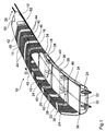
- Figure 1 shows a part of a rail vehicle 10 in a simplified, perspective and partially sectioned view.
- This embodiment is for one Designed as a freight train.
- Six vehicle segments 12 to 22 are shown with a length of approx. 4 meters over a centrally positioned landing gear 24 are supported on a pair of rails 26.
- single bogies each with a pair of wheels are provided.
- the The axis of the wheel pair is only in a direction perpendicular to the direction of travel Movable axis plane.
- This axis plane contains a straight line 32, which the Connecting the centers of the wheels.
- Each undercarriage 24 is not shown Spring and / or damping members attached to a support frame 34.
- the support frame 34 is rigid and extends within the respective vehicle segment essentially over the entire length and width of the jacket 36, but with a few centimeters from the inside.
- the jacket 36 is to ensure its defined articulation in the area of the axis plane and at its longitudinal ends with the support frame via special connecting elements 38 or 40 connected, which are further below with reference to FIGS. 2a to 2d individual are described.
- the vehicle segments 12 to 22 have separation points at their longitudinal ends 42 on which the jackets via (not shown here) flange connections are coupled to each other.
- the flange connection can also any other, essentially rigid connection type can be used, for example a welt connection or a zipper connection.
- a piping connection are adjacent coats by covering themselves over the entire circumference extending connector but with open ends coupled together, the one with piping at its longitudinal ends in both coats engages provided guide grooves.
- the connector is for coupling the Coats retractable into the guide grooves, so can also when separating the coats can be easily removed.
- the connector is in the circumferential direction of the jacket elastically deformable, but in the longitudinal and transverse directions of the Coat stiff.
- the jackets 36 are each made in one piece from fiber composite materials and have stiff and articulated sections.
- FIG. 1 shows stiff jacket sections 44 and 46 without hatching and articulated jacket sections 48 hatched.
- the rigid end portions 44 extend at this Rail vehicle each from the end faces of the segments over a length about 20 cm to the middle of the segment.
- Rigid middle sections 46 are each of the axial plane from about 40 cm each to both end faces. Between these rigid areas, each of which extends over the entire scope of the Extend jacket, articulated jacket sections 48 are formed.
- the vehicle segments 14 to 22 no windows are provided. Only head segments 12 have windows 50 and doors 52. The interior is loaded by the end faces of separate segments.
- the jacket can be used in individual segments 36 to facilitate loading also roof openings (not shown) and / or side wall doors, but only in the rigid middle sections 46, which are designed for this purpose with a correspondingly greater longitudinal extent are.
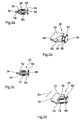
- FIG. 2a shows the first connecting element 38 in a cross-sectional view whose help the jacket 36 in the stiff section 46 on the axis plane the support frame 34 is attached.
- the same connecting element is shown in FIG. 2b shown a perspective view.
- Connecting elements 38 are on both Transverse sides of the support frame 34 are arranged opposite one another.
- the first connecting element 38 has a rectangular back plate 54, which with the jacket 36 is connected.
- the back plate 54 several Bores 56 has.
- a cylindrical extends from the back plate 54 Bolt 58 to the transverse side of the support frame 34.
- the back plate 54 and the Bolts 58 are made in one piece from a rigid material, preferably from metal manufactured.
- the bolt can alternatively be attached to the jacket with his be anchored or embedded in the back of the jacket. About from half to towards the front end of its longitudinal extent, the bolt 58 is fixed by one surrounded with rubber jacket 60 connected.
- Support frame 34 and jacket are not, however, by the connecting element 38 completely rigid.
- the support frame and the bolt 58 are small Distance from each other, so that the support frame 34 together with the outer jacket 62 of the connecting element to a certain extent on the bolt 58 can move, the rubber jacket 60 transversely the momentum of the support frame 34 picks up to the track and is elastically deformed accordingly, one of the Deflection opposing restoring force is generated. That way the jacket against high-frequency transmitted from the chassis to the support frame Dynamic driving impulses isolated.
- the first connecting element 38 therefore takes over the transmission of acceleration and tracking forces from the support frame to the jacket. Still isolated it protects against the transmission of short-term and high-frequency impulses.
- FIGS. 2c and 2d 40 An exemplary embodiment of the second connecting element is shown in FIGS. 2c and 2d 40 shown, with the help of the jacket near its long sides Ends supported on the support frame. Also the second connection elements 40 are opposite each other on both transverse sides of the support frame 34 arranged, with several connecting elements 38 arranged one behind the other could be.
- the cross-sectional view of Figure 2c shows that the principle Structure of the second connecting element 40 is similar to that of the first. However, based on the perspective representation in Figure 2d, the following differences to recognize: the second connecting element 40 has a square Bolt 66, the top 68 and bottom 70 of about half of their longitudinal extent to the support frame 34 with rubber layers 72 and 74 firmly connected are. The rubber layers are covered by outer shells 76 and 78, which extend over the length of the square pin 66 and to the support frame 34 are bent to firmly enclose them from above and below.
- the second connecting element tolerates 40 relative movements between support frame 34 and jacket parallel to the track level. Such relative movements occur regularly when driving through of track arches.
- the support frame and chassis rotate together about a vertical axis, the axis line 32 under right in the axis plane Angle cuts.
- the support frame 34 is put together by the action of the chassis with the shells 76 and 78 shifted relative to the square bolt 66.
- the rubber layers of the second connecting elements deform 40 parallel to the track level along and across the direction of travel. The deformations the outside and inside of the bow are different. The one from the rubber layers the restoring force generated limits the deflection and supports a restoring movement.
- the swivel angle of the support frame in a track curve of 250 m radius is about 1 degree for a 4 m long support frame.
- the Associated slight relative movement of the support frame in the longitudinal and transverse directions against the jacket is not hindered by the connecting element 40.
- the connecting elements 40 are therefore structurally in vertical direction significantly stiffer than in directions parallel to the track level.
- the deformation of the jacket is not hindered.
- the lower deformability the connecting elements 40 in the vertical direction is also important, if the support frame is loaded very unevenly. In this case take over the connecting elements 40 the task of supporting the support frame, whereby part of the load must be transferred to the jacket.
- the jacket When entering a track curve via a cant ramp, the jacket is of the vehicle segment on the one hand - as described above - bent and on the other others slightly twisted.
- the vertical deformability of the connecting elements is sufficiently high to allow torsional movement against the support frame.
- the different construction of the connecting elements 38 and 40 is from essential for the flexibility of the rail vehicle. Since that Support frame 34 against the first connecting elements 38 no movement in Can perform direction of the longitudinal axis, form chassis, support frame 34 and Sheath on the rigid central portions 46 a substantially rigid unit, the acts as a support point for the rail vehicle. Transmits at these points on the one hand the vehicle places its load on the track, on the other hand it is created here by the interaction of the wheels with the track braking, accelerating and Guidance forces, which are directly from the chassis via the support frame, however, under Interposition of the described damping levels - transfer to the jacket become. Between the support points, the coat is articulated Sections deformed accordingly. In this respect, the support points fulfill a skeletal function. The supporting frame is between the support points of adjacent segments and the jacket against each other in accordance with the second connecting elements 40 movable to the deformation of the articulated jacket sections when driving through not to be obstructed by track arches, track domes and depressions.
- the primary task of the support frame 34 is the transmission in this construction the vehicle load on the chassis. Leave the connecting elements 38 and 40 no substantial vertical relative movement of the support frame 34 against the jacket to.
- the suspension in the vertical direction through the rubber jackets 60 or layers So 72 and 74 is tough.
- Figure 3 shows a cross-sectional view of the vehicle segment 16 in a through the Line III-III marked in Figure 1 plane, that is, in an elastic section 48.
- the maximum transverse extent of the jacket is about 3.30 m, its maximum Height above the top edge of the rail about 3 m. Even the lower parts of the Use the jacket - taking into account dynamic driving effects, such as the suspension - available in accordance with the Railway Construction and Operating Regulations (EBO) standing regular light room as far as possible and can at maximum Spring deflection up to 13 to 8 cm above the top edge of the rail.
- the Jacket 36 is complete in this section, except for wheel passages closed.
- the support frame 34 is on the single chassis, not shown 24 attached.
- the distance between the supporting frame is bridged on the transverse sides and jacket, apart from the connecting elements 38 and 40, by one hand attachable to the support frame or jacket and on the other hand to the jacket or Support frame sealing lips.
- the Support frame 34 is made of metal in the present embodiment and plate-shaped. Construction method and material used However, support frames are used according to the requirements known technologies can be varied. For example, fiber composite materials can also be used used or a hybrid design can be applied.
- FIG. 4 shows a longitudinal view of two segments 90 and 92, one for passenger traffic provided second embodiment. Both segments have the same length of about 6 m. Like the segments of the first embodiment they each have a running gear in the middle below a pair of wheels 94 and are rigidly connected to one another via a flange connection 96 coupled. The positions of a support frame 98 are shown by dashed lines and an inner floor 100 indicated. This is shown below using FIG. 5 discussed in more detail.
- the first segment 90 has a jacket 102 with two in it provided windows 104 arranged near the longitudinal ends and 106 and a door device 108 which has a further window 110.
- the second segment 92 also has windows in the same arrangement and size 112 and 114. In addition, there are two windows 116 and 117 in the middle section intended. The windows and door fixtures are flush with the outside surface of the Sheath 102 fitted.
- elastic sections 118 of the segment jackets 90 and 92 in Figure 4 hatched.
- the order and longitudinal extension of elastic and stiff sections is both Segments identical. In this way the flexibility is the same in every segment trained and ensures a homogeneous adaptation of the rail vehicle as Everything on the track.
- the manufacture of the coats is also designed Different segment types are particularly economical, as only in the middle section either a door opening or a window opening must be provided, otherwise an identical production process can be followed. For Segments with a special interior, such as for a train restaurant, Sanitary facilities or drive units can change the arrangement and size of the Windows or doors are changed.
- the elastic sections extend 118 in each of the two segment types shown, on the one hand with one Distance of approx. 20 cm to the end of the segment over a length of approx. 30 cm in Direction of the near window 114 and 112 (and 104 and 106). More elastic Sections of the same length are on the other hand on both sides of the door 108 and the Center window 116 is provided towards the center of the segment.
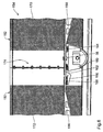
- FIG. 5 shows a cross-sectional view of the vehicle segment 92.
- the sectional plane is indicated in Figure 4 by the line V-V.
- the construction of the vehicle segment The underlying principle is that based on the first exemplary embodiment explained essentially the same.
- a support frame 120 is on a landing gear arranged in the middle of the longitudinal extent of the segment 122 attached.
- the wheels of the pair of wheels are mounted so that one of their centers connecting straight line 123 always lies in an axis plane that is perpendicular to the direction of travel stands.
- the pair of wheels can be both individually mounted wheels also formed by a wheel set with two wheels coupled via an axle become.
- a jacket 124 is supported on the transverse sides of the support frame 120.
- connection of the jacket to the support frame takes place essentially in the same way as has been described in detail with reference to Figures 1 and 2. Since the sectional plane of FIG. 5 is close to the axis plane of the vehicle segment 92 lies, the connecting elements 38 are shown here.
- the support frame 120 In deviation from the segment profile shown in FIG. 3, the support frame 120 a trough 126 arranged centrally in the transverse direction, which is for receiving vehicle engineering units extends along the segment, however, the area of the undercarriage. Two vertical side walls 128 and 130 delimit them Trough 126 from the cavity below the support frame 120, but have none essential supporting function.
- the support frame has longitudinal members on its underside 138 on.
- a rigid inner floor 132 At its transverse ends, which are at a distance from the Sheath are arranged on both sides of sealing lips 134 and 136, which are nestle up against the side wall of the coat and the space above of the inner floor over the entire length of the segment from the ones below Seal voids.
- the inner floor 132 on the support frame 120 are on both sides Arranged in the middle of the segment cross section bellows 140 and 142, which in on the Sockets 144 and 146 arranged underneath of the inner bottom 132 are embedded are.
- bellows are arranged one behind the other in the longitudinal direction intended.
- the load transfer from the inner floor to the support frame they provide extensive insulation due to their damping characteristics of the inside of driving dynamics impulses and thus for a calm and comfortable driving experience.
- the described storage and the elastic attachment to the side walls of the shell 124 allows a pivoting movement of the inner bottom 132 by one longitudinal axis running perpendicular to the cross-sectional plane through its center.
- This Construction provides the basis for a tilting technique when moving due to track arches the vehicle body remains unchanged and only the inside floor is inclined towards the middle of the bow.
- the pressure regulation and control of the bellows takes place in a manner known to the person skilled in the art from conventional tilting technology. Details of the pivotable mounting of the inner bottom 132 can be found in a patent application filed by the applicant at the same time.
- the passenger compartment formed above the inner floor 132 offers due to the width of the vehicle segment made possible by the invention of approx. 3.20 m more space than in known vehicles. This can be the case, for example Seating 148 can be used in rows of five, as indicated in Figure 5.
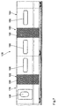
- FIG. 6 shows a third exemplary embodiment on the basis of a simplified longitudinal sectional drawing with an alternative suspension arrangement. The are shown longitudinal ends of two adjacent vehicle segments 150 and 152 one for rail vehicle 154 intended for the transportation of goods.
- the vehicle segments 150 and 152 have, as in the previous exemplary embodiments one supporting frame 156 or 158 each.
- the support frame 158 supports at its end on a single trolley 160.
- the between trolley 160 and Support frame 158 shown springs 162 and 164 symbolize a primary suspension, which, corresponding to what has been said for the description of FIGS. 1 and 2, Relative movements between the chassis and the support frame in directions parallel to Track level essentially suppressed.
- the support frame 156 of the vehicle segment 150 is with its adjacent End supported on the support frame 158.
- it has a support 166 which the support frame 156 is mounted on a rubber-metal element 168.
- This Connection of the support frames is detachable to separate the vehicle segments.
- the Rubber-metal element 168 has a similar characteristic to that based on 1 and 2 explained connecting element 40 and allows a relative movement of the support frames 156 and 158 when traversing track arches, depressions and crests.
- the jacket 170 of the vehicle segment 152 is over in the area of the axis plane Fasteners 38 attached to the support frame. Connecting elements 40 between the jacket 172 of the vehicle segment 150 and the support frame 156 are not required at this long end.
- the elastic is sufficient here Coupling via a sealing lip 84 (not shown) (see FIG. 3).
- Elastic portions of the shells 170 and 172 are as in the previous ones Figures are hatched.
- the coats are at the long ends stiff and rigidly coupled to one another with a flange connection 174.
- the vehicle segment 150 is at its other, not shown in Figure 6 Longitudinal end formed as the vehicle segment 152.
- the vehicle segment 152 is formed at its other end, not shown like vehicle segment 150 in Figure 6. In this way, each support frame is supported at both ends.
- This embodiment has the advantage that the jacket at one end both its function as part of the base or "skeleton elements" of vehicle 154 takes over and is therefore already rigidly designed for the manufacture of a rigid Connection to the jacket of the neighboring vehicle segment. This enables one greater flexibility in dividing the jacket into rigid and articulated sections. This design is therefore particularly suitable for configuration for the Passenger traffic.
- FIG. 7 Here is the fourth embodiment in A partial side view of a sectional vehicle 176 analogous to FIG. 4 shown.
- This is essentially in accordance with the exemplary embodiment Figure 6 constructed.
- the two vehicle segments 178 and 180 shown however have coats 182 and 184 designed for passenger transport Openings for windows 186 or a door device 188.
- Articulated jacket sections are in the middle of their longitudinal extent in these vehicle segments educated. Depending on the function of the vehicle segment and the associated
- the hinged jacket sections can be arranged in windows and doors however, it can also be formed at other locations along the longitudinal extent. Locked out are, as explained above, only as support and connection points serving longitudinal ends.
Landscapes
- Engineering & Computer Science (AREA)
- Mechanical Engineering (AREA)
- Life Sciences & Earth Sciences (AREA)
- Wood Science & Technology (AREA)
- Transportation (AREA)
- Body Structure For Vehicles (AREA)
- Chain Conveyers (AREA)
- Machines For Laying And Maintaining Railways (AREA)
- Optical Elements Other Than Lenses (AREA)
- Medicines Containing Antibodies Or Antigens For Use As Internal Diagnostic Agents (AREA)
- Organic Insulating Materials (AREA)
- Lining And Supports For Tunnels (AREA)
Claims (33)
- Segment de véhicule (12 à 22, 90, 92, 150, 152, 178, 180) pour véhicule articulé sur rails, comportant un châssis porteur (34, 98, 120, 156, 158) sur au moins une paire de roues (24, 122, 160) et une chemise extérieure de forme tubulaire dans sa section transversale (36, 102, 124, 170, 172, 182, 184) sur le châssis porteur (34, 98, 120), qui entoure des éléments intégrés (148) dans le segment de véhicule (12 à 22, 90, 92, 50, 152), l'axe longitudinal de la chemise (36, 102, 124, 170, 172, 182, 184) s'étendant dans le sens de circulation, caractérisé en ce que la chemise (36, 102, 124, 170, 172, 182, 184) peut être couplée rigidement avec la chemise d'un segment de véhicule voisin et présente au moins une section articulée de chemise (48, 102, 118, 190) qui est d'une longueur prédéfinie dans le sens de l'axe longitudinal.
- Segment de véhicule selon la revendication 1, caractérisé par une section transversale de la chemise (36, 102, 124, 170, 172, 182, 184) restant substantiellement identique sur toute la longueur du segment de véhicule.
- Segment de véhicule selon la revendication 1 ou 2, caractérisé en ce que la section articulée de la chemise (48, 102, 118, 190) est élastiquement déformable vis-à-vis de forces agissant transversalement par rapport à l'axe longitudinal.
- Segment de véhicule selon la revendication 3, caractérisé en ce que la déformabilité élastique de la section articulée de la chemise (48, 102, 118, 190) est plus faible vis-à-vis de forces dirigées à la verticale du plan de la voie que vis-à-vis de forces dirigées parallèlement au plan de la voie.
- Segment de véhicule selon la revendication 3 ou 4, caractérisé en ce que la section articulée de la chemise (48, 102, 118, 190) peut être tordue élastiquement autour de l'axe longitudinal.
- Segment de véhicule selon une des revendications précédentes, caractérisé en ce que la chemise (36, 102, 124, 170, 172, 182, 184) et/ou la section articulée de la chemise (48, 102, 118, 190) sont composées de plusieurs couches de matière.
- Segment de véhicule selon une des revendications précédentes, caractérisé en ce que la section articulée de la chemise (48, 102, 118, 190) présente au moins une couche contenant des fibres de verre, de polymère et/ou de carbone.
- Segment de véhicule selon une des revendications précédentes, caractérisé en ce que la section articulée de la chemise (48, 102, 118, 190) présente au moins une couche constituée de métal.
- Segment de véhicule selon une des revendications précédentes, caractérisé en ce que la chemise (36, 102, 124, 170, 172, 182, 184) est constituée en une seule pièce.
- Segment de véhicule selon une des revendications précédentes, caractérisé par des éléments de réglage pouvant être commandés servant à produire des forces qui provoquent une courbure ou un étirement élastique de la chemise (36, 102, 124, 170, 172, 182, 184), par lequel l'axe longitudinal de la chemise est courbé ou étiré.
- Segment de véhicule selon la revendication 10, caractérisé en ce que les éléments de réglage sont intégrés dans la chemise.
- Segment de véhicule selon la revendication 10 ou 11, caractérisé par des éléments de réglage fonctionnant mécaniquement.
- Segment de véhicule selon la revendication 10 ou 11, caractérisé en ce que les éléments de réglage fonctionnent au fluide.
- Segment de véhicule selon la revendication 10 ou 11, caractérisé en ce que les éléments de réglage fonctionnent par piézoélectricité ou électromagnétisme.
- Segment de véhicule selon une des revendications précédentes, caractérisé en ce que la chemise (102, 124, 182, 184) présente au moins une ouverture de fenêtre (104, 106, 112, 114, 116, 117, 186) ou une ouverture de porte (108, 188) et est conçue sous forme rigide sur l'extension longitudinale de cette ouverture.
- Segment de véhicule selon une des revendications précédentes, caractérisé en ce que le châssis porteur (34, 98, 120) est rigide.
- Segment de véhicule selon une des revendications précédentes, caractérisé en ce que le châssis porteur (34, 98, 120), vu en section transversale, présente un baquet (126, 128, 130) disposé au centre.
- Segment de véhicule selon une des revendications précédentes, caractérisé par une extension longitudinale de moins de 10 mètres.
- Segment de véhicule selon une des revendications précédentes, caractérisé par des moyens d'amortissement des mouvements transversaux entre le châssis porteur (34, 98, 120) et la paire de roues (24, 122, 160).
- Segment de véhicule selon une des revendications précédentes, caractérisé en ce que les roues de la paire de roues (24, 122, 160) sont fixées au châssis porteur (34, 98, 120) de manière à ce qu'une droite (123) reliant les points centraux des roues se trouve constamment dans un plan d'essieu du segment de véhicule situé transversalement par rapport au sens de circulation.
- Segment de véhicule selon une des revendications précédentes, caractérisé en ce que le châssis porteur (34, 98, 120, 156, 158) peut être couplé élastiquement aux châssis porteurs de segments de véhicule voisins.
- Segment de véhicule selon une des revendications précédentes, caractérisé par une paire de roues (24, 122, 160) qui est disposée approximativement au centre par rapport à l'extension longitudinale du châssis porteur (34, 98, 120).
- Segment de véhicule selon une des revendications 1 à 21, caractérisé par une paire de roues (160) qui est disposée à une extrémité du châssis porteur (158).
- Segment de véhicule selon une des revendications précédentes, caractérisé en ce que la chemise (36, 102, 124, 170, 172, 182, 184) est fixée au châssis porteur (34, 98, 120, 156, 158).
- Segment de véhicule selon la revendication 24, caractérisé en ce que la chemise (36, 102, 124, 170, 172, 182, 184) présente une première section longitudinale rigide (46) qui est couplée rigidement au châssis porteur dans le sens longitudinal ainsi que dans des sens à la verticale de la droite (123) reliant les points centraux des roues.
- Segment de véhicule selon une des revendications précédentes, caractérisé en ce que la chemise (36, 102, 124) présente une deuxième section longitudinale rigide (44) qui est couplée élastiquement au châssis porteur (34, 98, 120) avec possibilité de réinitialisation dans les sens parallèle et transversal par rapport au sens longitudinal.
- Segment de véhicule selon au moins une des revendications précédentes, caractérisé en ce que la première section longitudinale rigide (46) est couplée au châssis porteur (34, 98, 120) grâce à un premier (38) et la deuxième section longitudinale rigide (44) grâce à un deuxième (40) élément en métal-caoutchouc.
- Véhicule articulé sur rails (10), caractérisé en ce qu'il présente une multitude de segments de véhicule (12 à 22, 90, 92, 150, 152, 178, 180) couplés rigidement les uns aux autres selon une ou plusieurs des revendications 1 à 26.
- Véhicule articulé sur rails selon la revendication 28, caractérisé par une lèvre d'étanchéité ou une bande de joint entre les châssis porteurs voisins qui peuvent être fixés sur au moins un des deux châssis porteurs.
- Véhicule articulé sur rails selon une des revendications 28 et 29, caractérisé en ce que les segments de véhicule sont couplés les uns aux autres de manière à ce que respectivement une première extrémité du châssis porteur (156) sans paire de roues jouxte une deuxième extrémité du châssis porteur (158) comportant une paire de roues (160) et que la première extrémité du châssis porteur (156) s'appuie sur la deuxième extrémité du châssis porteur (158) et/ou sur la paire de roues (160).
- Véhicule articulé sur rails selon une des revendications 28 à 30, caractérisé par un raccord à brides (174) entre les chemises des éléments de véhicule voisins (150, 152).
- Véhicule articulé sur rails selon une des revendications 28 à 31, caractérisé par un raccord à fermeture-éclair entre les chemises des éléments de véhicule voisins.
- Véhicule articulé sur rails selon une des revendications 28 à 32, caractérisé par un raccord à cadre entre les chemises des éléments de véhicule voisins.
Applications Claiming Priority (3)
| Application Number | Priority Date | Filing Date | Title |
|---|---|---|---|
| DE19952733A DE19952733A1 (de) | 1999-10-27 | 1999-10-27 | Fahrzeugsegment für ein schienengebundenes Gliederfahrzeug |
| DE19952733 | 1999-10-27 | ||
| PCT/EP2000/010558 WO2001030628A1 (fr) | 1999-10-27 | 2000-10-26 | Segment de vehicule pour vehicule articule roulant sur rail |
Publications (2)
| Publication Number | Publication Date |
|---|---|
| EP1237771A1 EP1237771A1 (fr) | 2002-09-11 |
| EP1237771B1 true EP1237771B1 (fr) | 2003-05-28 |
Family
ID=7927669
Family Applications (1)
| Application Number | Title | Priority Date | Filing Date |
|---|---|---|---|
| EP00972873A Expired - Lifetime EP1237771B1 (fr) | 1999-10-27 | 2000-10-26 | Segment de vehicule pour vehicule articule roulant sur rail |
Country Status (7)
| Country | Link |
|---|---|
| EP (1) | EP1237771B1 (fr) |
| AT (1) | ATE241494T1 (fr) |
| AU (1) | AU1145101A (fr) |
| DE (2) | DE19952733A1 (fr) |
| DK (1) | DK1237771T3 (fr) |
| ES (1) | ES2195941T3 (fr) |
| WO (1) | WO2001030628A1 (fr) |
Families Citing this family (2)
| Publication number | Priority date | Publication date | Assignee | Title |
|---|---|---|---|---|
| DE10022543B4 (de) * | 1999-10-27 | 2005-08-18 | Db Reise & Touristik Ag | Schienengebundenes Fahrzeugsegment mit rumpfintegierter Fliehkraftkompensation |
| DE102018130813A1 (de) | 2018-12-04 | 2020-06-04 | Bombardier Transportation Gmbh | Fahrzeugsegment für ein mehrgliedriges schienenfahrzeug und schienenfahrzeug |
Family Cites Families (6)
| Publication number | Priority date | Publication date | Assignee | Title |
|---|---|---|---|---|
| US1875214A (en) * | 1927-10-14 | 1932-08-30 | Buderus Carl | Carriage for articulated trains |
| FR2562858B1 (fr) * | 1984-04-17 | 1987-09-18 | Regie Autonome Transports | Dispositif de communication entre deux elements de caisse d'un vehicule de type ferroviaire |
| FR2571010B1 (fr) * | 1984-10-02 | 1988-03-11 | Regie Autonome Transports | Dispositif d'intercirculation entre deux modules de rame ferroviaire |
| FR2724620B1 (fr) * | 1994-09-16 | 1997-01-10 | Lohr Ind | Passerelle deformable entre deux plans de chargement portes par des chassis successifs notamment ferroviaires |
| DE19749507B4 (de) * | 1997-11-08 | 2005-07-28 | Db Reise & Touristik Ag | Wagenkastenverbindung |
| EP1077855B1 (fr) * | 1998-05-13 | 2005-09-07 | DB Fernverkehr AG | Vehicule sur rails |
-
1999
- 1999-10-27 DE DE19952733A patent/DE19952733A1/de not_active Withdrawn
-
2000
- 2000-10-26 EP EP00972873A patent/EP1237771B1/fr not_active Expired - Lifetime
- 2000-10-26 DK DK00972873T patent/DK1237771T3/da active
- 2000-10-26 DE DE50002403T patent/DE50002403D1/de not_active Expired - Lifetime
- 2000-10-26 AU AU11451/01A patent/AU1145101A/en not_active Abandoned
- 2000-10-26 AT AT00972873T patent/ATE241494T1/de not_active IP Right Cessation
- 2000-10-26 WO PCT/EP2000/010558 patent/WO2001030628A1/fr not_active Ceased
- 2000-10-26 ES ES00972873T patent/ES2195941T3/es not_active Expired - Lifetime
Also Published As
| Publication number | Publication date |
|---|---|
| ES2195941T3 (es) | 2003-12-16 |
| DK1237771T3 (da) | 2003-06-23 |
| AU1145101A (en) | 2001-05-08 |
| DE50002403D1 (de) | 2003-07-03 |
| ATE241494T1 (de) | 2003-06-15 |
| EP1237771A1 (fr) | 2002-09-11 |
| DE19952733A1 (de) | 2001-05-10 |
| WO2001030628A1 (fr) | 2001-05-03 |
Similar Documents
| Publication | Publication Date | Title |
|---|---|---|
| EP2483125B1 (fr) | Système amortisseur pour la régulation de niveau dans un véhicule | |
| DE3812292A1 (de) | Einschienenbahn | |
| DE102013002096A1 (de) | Hochgeschwindigkeitszug mit geringem Energieumsatz | |
| EP0631917B1 (fr) | Véhicule ferroviaire | |
| EP0616936B1 (fr) | Train articulé | |
| EP0649782B1 (fr) | Véhicule ferroviaire et train de roulement pour un tel véhicule | |
| DE102020135041A1 (de) | Schweberahmen, Fahrzeug, Schienenanordnung und Magnetschwebebahn | |
| EP0838386B1 (fr) | Véhicule ferroviaire avec au moins un train de roulement et train de roulement pour un tel véhicule | |
| DE112013007135T5 (de) | Schienenfahrzeug, das Seitenkraft reduzieren kann, und Verfahren zum Reduzieren von Seitenkraft | |
| EP1237771B1 (fr) | Segment de vehicule pour vehicule articule roulant sur rail | |
| EP2204308A2 (fr) | Véhicule comprenant plusieurs caisses reliées de manière articulée | |
| EP2995523A1 (fr) | Chariot et train de roulement suspendus pour un sytème de transport à véhicules suspendus guidés sur rails | |
| EP1532033B1 (fr) | Bogie moteur pour un vehicule sur rails | |
| CH616372A5 (en) | Articulated train for public passenger transport | |
| EP0915001B1 (fr) | Connexion entre caisses des wagons | |
| DE19824013A1 (de) | Spurgeführtes Fahrzeugsystem | |
| EP0930210B1 (fr) | Train de roulement pour véhicules ferroviaires et véhicule ferroviaire avec au moins un tel train de roulement | |
| DE19703701A1 (de) | Zweiachsiges Fahrwerk für schienengebundene Transportsysteme | |
| EP1077855B1 (fr) | Vehicule sur rails | |
| DE9409044U1 (de) | Niederflur-Gelenktriebwagen, insbesondere für den Personenverkehr auf innerstädtischen Schienennetzen | |
| DE3326540A1 (de) | Laufradsatz mit zwei achsen fuer eisenbahn- und strassenbahnfahrzeuge, sowie eisenbahn- und strassenbahnfahrzeug mit einem solchen laufradsatz | |
| EP1237774B1 (fr) | Segment de vehicule roulant sur rail avec element de compensation de force centrifuge integre a l'armature | |
| DE19827818C2 (de) | Gliederfahrzeug | |
| DE19828900C2 (de) | Gliederfahrzeug | |
| DE10022543B4 (de) | Schienengebundenes Fahrzeugsegment mit rumpfintegierter Fliehkraftkompensation |
Legal Events
| Date | Code | Title | Description |
|---|---|---|---|
| PUAI | Public reference made under article 153(3) epc to a published international application that has entered the european phase |
Free format text: ORIGINAL CODE: 0009012 |
|
| 17P | Request for examination filed |
Effective date: 20020403 |
|
| AK | Designated contracting states |
Kind code of ref document: A1 Designated state(s): AT BE CH CY DE DK ES FI FR GB GR IE IT LI LU MC NL PT SE |
|
| AX | Request for extension of the european patent |
Free format text: AL;LT;LV;MK;RO;SI |
|
| GRAH | Despatch of communication of intention to grant a patent |
Free format text: ORIGINAL CODE: EPIDOS IGRA |
|
| GRAH | Despatch of communication of intention to grant a patent |
Free format text: ORIGINAL CODE: EPIDOS IGRA |
|
| RAP1 | Party data changed (applicant data changed or rights of an application transferred) |
Owner name: DB REISE & TOURISTIK AG |
|
| GRAA | (expected) grant |
Free format text: ORIGINAL CODE: 0009210 |
|
| AK | Designated contracting states |
Designated state(s): AT BE CH CY DE DK ES FI FR GB GR IE IT LI LU MC NL PT SE |
|
| PG25 | Lapsed in a contracting state [announced via postgrant information from national office to epo] |
Ref country code: IE Free format text: LAPSE BECAUSE OF FAILURE TO SUBMIT A TRANSLATION OF THE DESCRIPTION OR TO PAY THE FEE WITHIN THE PRESCRIBED TIME-LIMIT Effective date: 20030528 Ref country code: FI Free format text: LAPSE BECAUSE OF FAILURE TO SUBMIT A TRANSLATION OF THE DESCRIPTION OR TO PAY THE FEE WITHIN THE PRESCRIBED TIME-LIMIT Effective date: 20030528 |
|
| REG | Reference to a national code |
Ref country code: GB Ref legal event code: FG4D Free format text: NOT ENGLISH |
|
| REG | Reference to a national code |
Ref country code: CH Ref legal event code: EP |
|
| REG | Reference to a national code |
Ref country code: SE Ref legal event code: TRGR |
|
| REG | Reference to a national code |
Ref country code: CH Ref legal event code: NV Representative=s name: BUGNION S.A. |
|
| GBT | Gb: translation of ep patent filed (gb section 77(6)(a)/1977) | ||
| REG | Reference to a national code |
Ref country code: DK Ref legal event code: T3 |
|
| REG | Reference to a national code |
Ref country code: IE Ref legal event code: FG4D Free format text: GERMAN |
|
| REF | Corresponds to: |
Ref document number: 50002403 Country of ref document: DE Date of ref document: 20030703 Kind code of ref document: P |
|
| PG25 | Lapsed in a contracting state [announced via postgrant information from national office to epo] |
Ref country code: PT Free format text: LAPSE BECAUSE OF FAILURE TO SUBMIT A TRANSLATION OF THE DESCRIPTION OR TO PAY THE FEE WITHIN THE PRESCRIBED TIME-LIMIT Effective date: 20030828 Ref country code: GR Free format text: LAPSE BECAUSE OF FAILURE TO SUBMIT A TRANSLATION OF THE DESCRIPTION OR TO PAY THE FEE WITHIN THE PRESCRIBED TIME-LIMIT Effective date: 20030828 |
|
| ET | Fr: translation filed | ||
| PG25 | Lapsed in a contracting state [announced via postgrant information from national office to epo] |
Ref country code: LU Free format text: LAPSE BECAUSE OF NON-PAYMENT OF DUE FEES Effective date: 20031026 Ref country code: CY Free format text: LAPSE BECAUSE OF FAILURE TO SUBMIT A TRANSLATION OF THE DESCRIPTION OR TO PAY THE FEE WITHIN THE PRESCRIBED TIME-LIMIT Effective date: 20031026 |
|
| PG25 | Lapsed in a contracting state [announced via postgrant information from national office to epo] |
Ref country code: MC Free format text: LAPSE BECAUSE OF NON-PAYMENT OF DUE FEES Effective date: 20031031 Ref country code: BE Free format text: LAPSE BECAUSE OF NON-PAYMENT OF DUE FEES Effective date: 20031031 |
|
| LTIE | Lt: invalidation of european patent or patent extension |
Effective date: 20030528 |
|
| REG | Reference to a national code |
Ref country code: ES Ref legal event code: FG2A Ref document number: 2195941 Country of ref document: ES Kind code of ref document: T3 |
|
| REG | Reference to a national code |
Ref country code: IE Ref legal event code: FD4D |
|
| PLBE | No opposition filed within time limit |
Free format text: ORIGINAL CODE: 0009261 |
|
| STAA | Information on the status of an ep patent application or granted ep patent |
Free format text: STATUS: NO OPPOSITION FILED WITHIN TIME LIMIT |
|
| BERE | Be: lapsed |
Owner name: *DB REISE & TOURISTIK A.G. Effective date: 20031031 |
|
| 26N | No opposition filed |
Effective date: 20040302 |
|
| PGFP | Annual fee paid to national office [announced via postgrant information from national office to epo] |
Ref country code: GB Payment date: 20041012 Year of fee payment: 5 |
|
| PGFP | Annual fee paid to national office [announced via postgrant information from national office to epo] |
Ref country code: NL Payment date: 20041019 Year of fee payment: 5 Ref country code: FR Payment date: 20041019 Year of fee payment: 5 |
|
| PGFP | Annual fee paid to national office [announced via postgrant information from national office to epo] |
Ref country code: AT Payment date: 20041022 Year of fee payment: 5 |
|
| PGFP | Annual fee paid to national office [announced via postgrant information from national office to epo] |
Ref country code: SE Payment date: 20041025 Year of fee payment: 5 Ref country code: CH Payment date: 20041025 Year of fee payment: 5 |
|
| PGFP | Annual fee paid to national office [announced via postgrant information from national office to epo] |
Ref country code: ES Payment date: 20041026 Year of fee payment: 5 Ref country code: DK Payment date: 20041026 Year of fee payment: 5 |
|
| PGFP | Annual fee paid to national office [announced via postgrant information from national office to epo] |
Ref country code: DE Payment date: 20041031 Year of fee payment: 5 |
|
| PG25 | Lapsed in a contracting state [announced via postgrant information from national office to epo] |
Ref country code: IT Free format text: LAPSE BECAUSE OF NON-PAYMENT OF DUE FEES Effective date: 20051026 Ref country code: AT Free format text: LAPSE BECAUSE OF NON-PAYMENT OF DUE FEES Effective date: 20051026 |
|
| PG25 | Lapsed in a contracting state [announced via postgrant information from national office to epo] |
Ref country code: SE Free format text: LAPSE BECAUSE OF NON-PAYMENT OF DUE FEES Effective date: 20051027 Ref country code: ES Free format text: LAPSE BECAUSE OF NON-PAYMENT OF DUE FEES Effective date: 20051027 |
|
| PG25 | Lapsed in a contracting state [announced via postgrant information from national office to epo] |
Ref country code: LI Free format text: LAPSE BECAUSE OF NON-PAYMENT OF DUE FEES Effective date: 20051031 Ref country code: DK Free format text: LAPSE BECAUSE OF NON-PAYMENT OF DUE FEES Effective date: 20051031 Ref country code: CH Free format text: LAPSE BECAUSE OF NON-PAYMENT OF DUE FEES Effective date: 20051031 |
|
| PG25 | Lapsed in a contracting state [announced via postgrant information from national office to epo] |
Ref country code: DE Free format text: LAPSE BECAUSE OF THE APPLICANT RENOUNCES Effective date: 20060320 |
|
| PG25 | Lapsed in a contracting state [announced via postgrant information from national office to epo] |
Ref country code: NL Free format text: LAPSE BECAUSE OF NON-PAYMENT OF DUE FEES Effective date: 20060501 |
|
| REG | Reference to a national code |
Ref country code: DK Ref legal event code: EBP |
|
| REG | Reference to a national code |
Ref country code: CH Ref legal event code: PL |
|
| EUG | Se: european patent has lapsed | ||
| GBPC | Gb: european patent ceased through non-payment of renewal fee |
Effective date: 20051026 |
|
| PG25 | Lapsed in a contracting state [announced via postgrant information from national office to epo] |
Ref country code: FR Free format text: LAPSE BECAUSE OF NON-PAYMENT OF DUE FEES Effective date: 20060630 |
|
| NLV4 | Nl: lapsed or anulled due to non-payment of the annual fee |
Effective date: 20060501 |
|
| REG | Reference to a national code |
Ref country code: FR Ref legal event code: ST Effective date: 20060630 |
|
| REG | Reference to a national code |
Ref country code: ES Ref legal event code: FD2A Effective date: 20051027 |