EP1237304A2 - Optischer Pulsformer - Google Patents
Optischer Pulsformer Download PDFInfo
- Publication number
- EP1237304A2 EP1237304A2 EP02002297A EP02002297A EP1237304A2 EP 1237304 A2 EP1237304 A2 EP 1237304A2 EP 02002297 A EP02002297 A EP 02002297A EP 02002297 A EP02002297 A EP 02002297A EP 1237304 A2 EP1237304 A2 EP 1237304A2
- Authority
- EP
- European Patent Office
- Prior art keywords
- optical
- nonlinear
- wavelength
- pulse
- waveform
- Prior art date
- Legal status (The legal status is an assumption and is not a legal conclusion. Google has not performed a legal analysis and makes no representation as to the accuracy of the status listed.)
- Withdrawn
Links
Images


Classifications
-
- G—PHYSICS
- G02—OPTICS
- G02F—OPTICAL DEVICES OR ARRANGEMENTS FOR THE CONTROL OF LIGHT BY MODIFICATION OF THE OPTICAL PROPERTIES OF THE MEDIA OF THE ELEMENTS INVOLVED THEREIN; NON-LINEAR OPTICS; FREQUENCY-CHANGING OF LIGHT; OPTICAL LOGIC ELEMENTS; OPTICAL ANALOGUE/DIGITAL CONVERTERS
- G02F1/00—Devices or arrangements for the control of the intensity, colour, phase, polarisation or direction of light arriving from an independent light source, e.g. switching, gating or modulating; Non-linear optics
- G02F1/35—Non-linear optics
-
- G—PHYSICS
- G02—OPTICS
- G02B—OPTICAL ELEMENTS, SYSTEMS OR APPARATUS
- G02B6/00—Light guides; Structural details of arrangements comprising light guides and other optical elements, e.g. couplings
- G02B6/24—Coupling light guides
- G02B6/26—Optical coupling means
- G02B6/28—Optical coupling means having data bus means, i.e. plural waveguides interconnected and providing an inherently bidirectional system by mixing and splitting signals
- G02B6/293—Optical coupling means having data bus means, i.e. plural waveguides interconnected and providing an inherently bidirectional system by mixing and splitting signals with wavelength selective means
- G02B6/29371—Optical coupling means having data bus means, i.e. plural waveguides interconnected and providing an inherently bidirectional system by mixing and splitting signals with wavelength selective means operating principle based on material dispersion
- G02B6/29374—Optical coupling means having data bus means, i.e. plural waveguides interconnected and providing an inherently bidirectional system by mixing and splitting signals with wavelength selective means operating principle based on material dispersion in an optical light guide
- G02B6/29376—Optical coupling means having data bus means, i.e. plural waveguides interconnected and providing an inherently bidirectional system by mixing and splitting signals with wavelength selective means operating principle based on material dispersion in an optical light guide coupling light guides for controlling wavelength dispersion, e.g. by concatenation of two light guides having different dispersion properties
- G02B6/29377—Optical coupling means having data bus means, i.e. plural waveguides interconnected and providing an inherently bidirectional system by mixing and splitting signals with wavelength selective means operating principle based on material dispersion in an optical light guide coupling light guides for controlling wavelength dispersion, e.g. by concatenation of two light guides having different dispersion properties controlling dispersion around 1550 nm, i.e. S, C, L and U bands from 1460-1675 nm
-
- H—ELECTRICITY
- H04—ELECTRIC COMMUNICATION TECHNIQUE
- H04B—TRANSMISSION
- H04B10/00—Transmission systems employing electromagnetic waves other than radio-waves, e.g. infrared, visible or ultraviolet light, or employing corpuscular radiation, e.g. quantum communication
- H04B10/50—Transmitters
- H04B10/501—Structural aspects
- H04B10/503—Laser transmitters
-
- H—ELECTRICITY
- H04—ELECTRIC COMMUNICATION TECHNIQUE
- H04B—TRANSMISSION
- H04B10/00—Transmission systems employing electromagnetic waves other than radio-waves, e.g. infrared, visible or ultraviolet light, or employing corpuscular radiation, e.g. quantum communication
- H04B10/50—Transmitters
- H04B10/508—Pulse generation, e.g. generation of solitons
-
- H—ELECTRICITY
- H04—ELECTRIC COMMUNICATION TECHNIQUE
- H04B—TRANSMISSION
- H04B10/00—Transmission systems employing electromagnetic waves other than radio-waves, e.g. infrared, visible or ultraviolet light, or employing corpuscular radiation, e.g. quantum communication
- H04B10/50—Transmitters
- H04B10/572—Wavelength control
-
- G—PHYSICS
- G02—OPTICS
- G02B—OPTICAL ELEMENTS, SYSTEMS OR APPARATUS
- G02B6/00—Light guides; Structural details of arrangements comprising light guides and other optical elements, e.g. couplings
- G02B6/24—Coupling light guides
- G02B6/26—Optical coupling means
- G02B6/28—Optical coupling means having data bus means, i.e. plural waveguides interconnected and providing an inherently bidirectional system by mixing and splitting signals
- G02B6/293—Optical coupling means having data bus means, i.e. plural waveguides interconnected and providing an inherently bidirectional system by mixing and splitting signals with wavelength selective means
- G02B6/29304—Optical coupling means having data bus means, i.e. plural waveguides interconnected and providing an inherently bidirectional system by mixing and splitting signals with wavelength selective means operating by diffraction, e.g. grating
- G02B6/29316—Light guides comprising a diffractive element, e.g. grating in or on the light guide such that diffracted light is confined in the light guide
- G02B6/29317—Light guides of the optical fibre type
- G02B6/29319—With a cascade of diffractive elements or of diffraction operations
-
- G—PHYSICS
- G02—OPTICS
- G02F—OPTICAL DEVICES OR ARRANGEMENTS FOR THE CONTROL OF LIGHT BY MODIFICATION OF THE OPTICAL PROPERTIES OF THE MEDIA OF THE ELEMENTS INVOLVED THEREIN; NON-LINEAR OPTICS; FREQUENCY-CHANGING OF LIGHT; OPTICAL LOGIC ELEMENTS; OPTICAL ANALOGUE/DIGITAL CONVERTERS
- G02F2203/00—Function characteristic
- G02F2203/26—Pulse shaping; Apparatus or methods therefor
-
- H—ELECTRICITY
- H01—ELECTRIC ELEMENTS
- H01S—DEVICES USING THE PROCESS OF LIGHT AMPLIFICATION BY STIMULATED EMISSION OF RADIATION [LASER] TO AMPLIFY OR GENERATE LIGHT; DEVICES USING STIMULATED EMISSION OF ELECTROMAGNETIC RADIATION IN WAVE RANGES OTHER THAN OPTICAL
- H01S3/00—Lasers, i.e. devices using stimulated emission of electromagnetic radiation in the infrared, visible or ultraviolet wave range
- H01S3/005—Optical devices external to the laser cavity, specially adapted for lasers, e.g. for homogenisation of the beam or for manipulating laser pulses, e.g. pulse shaping
- H01S3/0057—Temporal shaping, e.g. pulse compression, frequency chirping
Definitions
- the invention relates to waveform converters, with some embodiments suitable for use as waveform converters for optical communication systems.
- Optical fibers are widely used for communicating information, such as in large telecommunication systems, primarily owing to their reliability, their insensitivity to electrical interference, and their high data capacity. It is desirable to use fiber optic communication networks as efficiently as possible, especially when the networks are implemented over long distances. In order to transmit optical signals over these long distances, the signals generally must be amplified before transmission to compensate for transmission losses.
- An erbium-doped fiber amplifier for example, is capable of directly amplifying signal light to obtain a high-intensity optical signal in the 1550 nm wavelength band, thereby enabling compensation for transmission loss in optical fibers forming optical paths, and hence, unrepeated transmission over several thousand kilometers.
- the amount of information that is sent in a specific amount of time can be increased by making optical pulses as short as possible.
- Short pulses are advantageous in high data rate transmission techniques such as wavelength division multiplexing (WDM) and time division multiplexing (TDM).
- optical signals generally require a narrow pulse width in a selected wavelength band.
- dispersive and nonlinear effects in the transmission fibers can be used advantageously to modify the pulse width/ shape of an optical signal.
- a number of signals may need to change their wavelengths in addition to modifying and/or controlling the shape of the optical pulse.
- One approach to converting the wavelength of an optical signal is opto-electro-optical, wherein an optical signal is converted into an electrical signal using a photoelectric converter (i.e. photo-detector, photodiode), and the electrical signal drives a light source at a different wavelength.
- a photoelectric converter i.e. photo-detector, photodiode
- This method entails problems such as high operating costs and difficulty in controlling the pulse width of the signal.
- Additional methods for directly converting the wavelength of an optical signal utilize a semiconductor amplifier and nonlinearity properties of optical fibers.
- the method comprises directing the input signal at a first wavelength onto a semiconductor device, which is amplifying a steady signal at a second wavelength than the input signal.
- the input signal changes the amount of amplification at the second wavelength, thereby modulating the steady signal to reproduce the input signal at a different wavelength.
- a disadvantage, however, to using a semiconductor amplifier is a rather low signal to noise ratio.
- the nonlinearity of an optical transmission medium can also be utilized such that idler light generated on the basis of a four-wave mixing (FWM) phenomenon is obtained as a wavelength converted signal.
- FWM four-wave mixing
- an optical pulse waveform converter comprises a coupled plurality of optical elements.
- the optical elements comprise an optical pulse input port configured to receive an input optical pulse, a nonlinear optical element configured to broaden a wavelength content of an optical pulse routed through the nonlinear optical element, a dispersive optical element configured to modify a temporal profile of an optical pulse routed through the dispersive optical element, and a wavelength selecting optical element configured to pass selected wavelength components of an optical pulse routed through the wavelength selecting optical element.
- an optical pulse output port configured to output an optical pulse comprising different optical characteristics than the input optical pulse.
- a method for converting an optical pulse waveform comprises broadening the wavelength content and narrowing the temporal width of an input optical pulse to produce a modified optical pulse.
- the method also comprises selecting a portion of the wavelength content of the modified optical pulse to produce an output optical pulse.
- the broadening and narrowing may be performed in any order.
- an optical pulse light source comprises a modulated signal light source having output pulses characterized by a temporal waveform and a wavelength content.
- the light source further comprises a waveform converter coupled to receive the output pulses from the signal light source and comprising a nonlinear optical element, a dispersive optical element, and a wavelength selecting optical element, wherein the waveform converter is configured to output optical pulses which have different wavelength content than the optical pulses output from the signal light source.
- Figure 1 is a block diagram of one embodiment of an optical waveform converter.
- Figure 2A is a time domain graphical illustration of an exemplary optical signal applied to the waveform converter of Figure 1.
- Figure 2B is a graphical illustration of an optical spectrum graph of the optical signal of Figure 2A.
- Figure 3A is a time domain graphical illustration of the optical signal of Figure 2A after passing through the nonlinear medium and dispersion medium of the waveform converter of Figure 1.
- Figure 3B is a graphical illustration of an optical spectrum graph of the optical signal of Figure 3A.
- Figure 4A is a time domain graphical illustration of the optical signal of Figure 3A after passing through the wavelength selecting medium of the waveform converter of Figure 2.
- Figure 4B is a graphical illustration of an optical spectrum graph of the optical signal of Figure 4A.
- Figure 5 is a block diagram of an additional embodiment of an optical waveform converter.
- Figure 6 is a block diagram of one embodiment of a two phase optical waveform converter.
- Figure 7 is a block diagram of an additional embodiment of an optical waveform converter.
- Figure 8A is an illustration of an optical transmission path comprising a plurality of optical fibers.
- Figure 8B is a graphical illustration of dispersion levels versus fiber length corresponding to the optical fibers of Figure 8A.
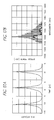
- Figure 9A is a time domain graphical illustration of an exemplary optical signal.
- Figure 9B is a graphical illustration of an optical spectrum graph of the time domain waveform of Figure 9A.
- Figure 10A is a graphical illustration of an optical spectrum graph of the optical signal of Figure 9A following transmission through a first optical fiber of the optical transmission path of Figure 8A.
- Figure 10B is a time domain graphical illustration corresponding to the optical spectrum of Figure 10A.
- Figure 11A is a time domain graphical illustration of the optical signal of Figure 10B following transmission through a second optical fiber of the optical transmission path of Figure 8A.
- Figure 11B is a graphical illustration of an optical spectrum graph of the time domain waveform of Figure 11A.
- Figure 12A is a graphical illustration of an optical spectrum of the optical signal of Figure 11A following transmission through a third optical fiber of the optical transmission path of Figure 8A.
- Figure 12B is a time domain graphical illustration corresponding to the optical spectrum of Figure 12A.
- Figure 13A is a time domain graphical illustration of the optical signal of Figure 12B following transmission through a fourth optical fiber of the optical transmission path of Figure 8A.
- Figure 13B is graphical illustration of an optical spectrum of the time domain waveform of Figure 13A.
- Figure 14 is a block diagram of an additional embodiment of an optical waveform converter.
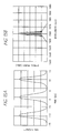
- Figure 15A is a graphical illustration of an autocorrelation function of an amplified signal from the waveform converter of Figure 14.
- Figure 15B is a graphical illustration of an optical spectrum of the amplified signal of Figure 15A.
- Figure 16A is a graphical illustration of an autocorrelation function of an optical signal produced at the dispersion medium output section of the waveform converter of Figure 14.
- Figure 16B is a graphical illustration of an optical spectrum of the optical signal of Figure 16A.
- Figure 17A is a graphical illustration of an autocorrelation function of an optical signal produced at the output signal section of the waveform converter of Figure 14.
- Figure 17B is a graphical illustration of an optical spectrum of the optical signal of Figure 17A.
- Figure 18 is a block diagram of an additional embodiment of an optical waveform converter.
- Figure 19 is a block diagram of one embodiment of an optical pulse light source.
- the frequency content of optical pulses are changed in an efficient and effective manner that provides control over both the wavelength content and temporal profiles of the output pulses produced with systems and methods made in accordance with the principles presented herein.
- methods of optical waveform conversion include receiving an input optical pulse waveform, broadening the wavelength content of the input optical pulse waveform, and selecting a desired wavelength range from within the broadened optical spectrum.
- the input optical pulse is both broadened in wavelength content and narrowed in temporal width prior to selecting the desired wavelengths from the broadened wavelength content.
- Systems implementing this method may, for example, route the input optical pulse to a medium having nonlinear optical characteristics to broaden the wavelength spectrum of the pulse.
- the pulse may also be routed through a dispersive medium to narrow the width of the pulse in time.
- the desired wavelength range for the output pulse can be selected with a grating, filter, or other wavelength selecting optical element.
- Such a system and method is very flexible and cost effective because the functions can be performed in a variety of different orders.
- a variety of optical elements are available to perform these functions.
- a single optical element can perform more than one of the waveform converting functions at the same time.
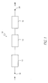
- FIG. 1 is a block diagram of one embodiment of an optical waveform converter 10.
- the waveform converter 10 comprises a plurality of elements which may be optically connected in series as shown in Figure 1, but which may be combined or joined in other ways, some examples of which are provided further below.
- the elements of the waveform converter of Figure 1 comprise a nonlinear medium 12 having a nonlinear effect on optical pulses, a dispersion medium 14 having a dispersion effect on optical pulses, and a wavelength selecting element 16 for selecting spectral components of the optical waveform in a desired wavelength region.
- the converter 10 typically also includes an input port 18 and output port 20 for receiving and emitting signals respectively.
- An optical input signal can be supplied to an input signal section 18 for transmission through the elements 12, 14, 16 of the waveform converter 10 to produce an output signal at an output signal section 20.
- Figures 2 through 4 illustrate the effects of the elements 12, 14, 16 of the waveform converter 10 on an optical pulse signal.
- An exemplary optical signal (optical pulses), having a time domain waveform 22 with a pulse width 24 as shown in Figure 3A, and an optical spectrum 26 as shown in Figure 3B, will be used to illustrate the effects of this embodiment of the waveform converter 10.
- the wavelength content referred to also as the optical spectrum of the signal is widened by the nonlinear effect of the nonlinear medium 12.
- the duration, or temporal width, of the optical pulse is reduced by the dispersion effect of the dispersion medium 14.
- Figure 3A illustrates a time domain waveform 30 of the optical signal
- Figure 3B illustrates an optical spectrum 32 of the optical signal after passing through the nonlinear medium 12 and the dispersion medium 14.
- a pulse width 34 of the optical signal has been reduced by the nonlinear medium 12 as compared to the pulse width 24 of the original waveform 22.
- the optical spectrum 32 shown in Figure 3B is wider than the spectrum 26 shown in Figure 3B also due to the effects of the nonlinear medium 12.
- the wavelength selecting element 16 is characterized by a wavelength pass band that selects spectral components of the optical signal from the optical spectrum 32 shown in Figure 3B, in the desired wavelength range.
- the resulting optical signal 40 is shown in Figures 4A and 4B having a pulse width 42, with energy content in the wavelength range shown in the optical spectrum 44 of Figure 5B.
- the elements 12, 14, 16 of the waveform converter 10 do not have to be arranged in the order described and shown in Figure 1.
- the elements can be arranged such that the nonlinear medium 12 and the dispersion medium 14 are optically connected in an order such that the signal passes through the dispersion medium 14 before the nonlinear medium 12.
- the dispersion medium 14 can then first correct the chirping in the signal, and the signal can then propagate through the nonlinear medium 12 to widen the optical spectrum of the signal, followed by selection of the desired wavelength range by the wavelength selecting element 16.
- Each of the elements 12, 14, 16 may comprise more than one optical component.
- an additional embodiment of the waveform converter 10 may employ a double-element stage in place of the single-element stage using the above described elements 12, 14, 16.
- a double-element stage can be formed by connecting two or more components, each corresponding to an element 12, 14, and 16, so as to enable shaping of different optical pulses.
- each of the above described elements 12, 14, 16 is not limited to a single function.
- a chirped fiber bragg grating for example, having a dispersion effect and a wavelength selecting function may be used.
- the number of components comprising the waveform converter can be reduced in comparison to the converter 10 shown in Figure 1 while having the same effect on an optical signal.
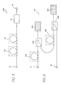
- FIG. 5 illustrates an additional embodiment of the waveform converter 10.
- the nonlinear medium 12 and the dispersion medium 14 are implemented with optical fibers 52, 54 having different nonlinear coefficients and dispersion characteristics.
- a 1550 nm band zero-dispersion shifted fiber (dispersion shifted fiber (DSF)) can be used as the nonlinear medium 52
- a 1300 nm band zero-dispersion fiber (single-mode fiber (SMF)) can be used as the dispersion medium 54.
- ⁇ 2 ⁇ ⁇ n 2 A eff ⁇ ⁇ wavelength n 2 ⁇ nonlinear refractive index
- the nonlinear effect on optical pulses dominates the dispersion effect.
- the SMF 54 the dispersion effect dominates the nonlinear effect. Consequently, in the waveform converter 50 the optical spectrum of pulses is widened by the DSF 52, the duration of the pulses is narrowed by the SMF 54, and the spectral components in the desired wavelength range are selected by the wavelength selecting element 16.
- the final optical signal obtained at the output signal section 20 has shaped optical pulse widths with the desired wavelength content.
- the waveform converter 50 effectively reduces the transmission loss of signal power of an optical signal transmitted through it due to the particular characteristics of the optical fibers 52, 54, as discussed above, used as the nonlinear and dispersion mediums.
- the wavelength selecting element 16 does not have to be located after the DSF 52 and the SMF 54 as shown in Figure 5.
- the wavelength selecting element 18 may be placed, for example, between the DSF 52 and the SMF 54.
- a highly nonlinear optical fiber having particular characteristics, such as those shown in Table 1, can be used favorably to replace the DSF 52.
- the ⁇ value of the highly nonlinear optical fiber in the table, a 1550 nm band zero-dispersion fiber, is approximately five times larger than that of ordinary 1550 nm band zero-dispersion DSF's which have a ⁇ value of approximately 2.5 W -1 km -1 .
- Zero-dispersion wavelength ( ⁇ 0 ) 1565.5 nm Dispersion Slope 0.029 ps/nm 2 /km
- the length of the fiber can be reduced in comparison with that of the ordinary optical fiber in the converter 50.
- the nonlinear coefficient is greater than about 5.0 W -1 km -1 , more preferably greater than about 10.0 W -1 km -1 .
- the entire configuration of the converter can be simplified, the polarization of transmitted optical pulses can be limited, and the transmission loss can be reduced.
- the converter can generate an optical pulse having a widened optical spectrum with considerably low influence from polarization dispersion following transmission through the dispersion medium.
- Figure 6 illustrates an additional embodiment of a waveform converter 60 having two stages.
- the first stage of the waveform converter 60 is formed using a DSF 52A similar to that of Figure 5, and a chirped fiber grating 62A in place of the SMF 54 of Figure 6.
- the DSF 52A and the chirped fiber grating 62A are connected by an optical circulator 64A, which also connects the first stage of the converter 60 to the second stage of the converter 60.
- the second stage of the converter has similar components 52B, 62B, 64B to the first stage, and the optical circulator 64B is connected to the output signal section 20 through a second chirped fiber grating 62B.
- the chirped fiber grating 62A-B in the waveform converter 60 functions as a dispersion medium as well as a wavelength selecting element. Therefore, an optical pulse signal supplied to the input signal section 18 of the converter 60 is converted into an optical pulse having a shaped pulse width and a desired wavelength.
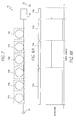
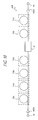
- Figure 7 illustrates an additional embodiment of a waveform converter 70.
- This converter embodiment 70 is formed by alternately disposing two types of optical fibers 72, 74, wherein each type of fiber differs from the other in nonlinearity and dispersion characteristics.
- a total of six optical fibers 72A-C, 74A-C are used in the converter 70 of Figure 7, optically connected to the wavelength selecting element 16.
- the number of optical fibers that can be used is not limited to six, and either a larger or smaller number of fibers can be used. More specifically, the converter 70 can be designed such that the first type of optical fibers 72A-C function as a nonlinear medium and the second type of optical fibers 74A-C function as a dispersion medium.
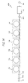
- Figure 8 illustrates an optical transmission path 80 formed by connecting two types of optical fibers differing in dispersion characteristics and length comprising DSF's 72A-B, and SMF's 74A-B.
- the combination of fibers illustrated in Figure 8 is sometimes referred to as a comb-like dispersion profiled fiber (CDPF).
- CDPF comb-like dispersion profiled fiber
- the example presented to qualitatively describe the waveform conversion process comprises providing beat light to the optical transmission path 80 of Figure 8.
- the beat light may be created by multiplexing two laser light beams having slightly different wavelengths.
- a nonlinear effect produced in the DSF's 72A and 72B, and chirp compensation provided by the SMF's 74A and 74B contribute to pulse shaping of the beat light.
- a time-domain waveform 90 as shown in Figure 9A, and an optical spectrum 92 as shown in Figure 9B with two wavelengths 94, 96 will be supplied to the optical transmission path 80.
- four-wave mixing (FWM) between the two-wavelength 94, 96 optical pulses produces sideband components 102A-B, 104A-B in the optical spectrum, as shown in Figure 10A, thereby causing chirping in the signal.
- the time-domain waveform corresponding to the spectrum of Figure 10A is illustrated in Figure 10B, where it can be seen that the temporal waveform is substantially unchanged from that of Figure 10A.
- an anomalous dispersion effect is exerted on the transmitted optical pulses of Figure 11B to compensate for chirping in the rising and falling portions of the optical pulses.
- the dispersion effect thereby reduces the optical pulse width, which is illustrated in the time-domain waveform of Figure 11A along with increased optical peak power.
- the optical spectrum corresponding to the waveform of Figure 11A is illustrated in Figure 11B, such that the optical spectrum from Figure 10A is substantially maintained.
- the optical pulse is then transmitted from the first-stage SMF 74A to the second-stage DSF 72B where a nonlinear effect due to self phase modulation (SPM) is exerted on the optical pulse to cause down-chirping in the rising portion of the optical pulse, and up-chirping in the falling portion of the optical pulse.
- SPM self phase modulation
- the nonlinear effect thereby widens the optical spectrum of the optical signal as shown in Figure 12A.
- the time domain waveform corresponding to the optical spectrum of Figure 12A is illustrated in Figure 12B, wherein the temporal waveform is substantially unchanged from that of Figure 11A.
- an input optical pulse can be reduced in pulse width in steps in addition to widening of the optical spectrum.
- Spectral components in the desired wavelength can then be selected from the widened optical spectrum.
- a waveform shaping section in the optical transmission path can be formed for shaping a time-domain waveform without using an optical fiber having a special dispersion structure, such as a dispersion-decreasing fiber wherein dispersion is reduced in the light propagation direction, corresponding to that of the waveform shaping section.
- a special dispersion structure such as a dispersion-decreasing fiber wherein dispersion is reduced in the light propagation direction, corresponding to that of the waveform shaping section.
- the combination of optical fibers can be optimized by adjusting the lengths of the fibers in relation to the dispersion characteristics of the fibers, and specifications relating to the input optical pulse, such as optical power, pulse width, and pulse period.
- the converter 70 of Figure 7 employs the above described functions of the optical transmission path. More specifically, an optical pulse output signal from the SMF 74C of the converter 70 has a reduced pulse width and a widened optical spectrum. Spectral components in the desired wavelength range can then be selected form the widened optical spectrum by the wavelength selecting element 16. Thus, an optical pulse, having a shaped pulse width and desired wavelength, can be obtained from the converter 70 at the output signal section 20.
- the converter 70 of Figure 7 utilizes optical fibers as nonlinear and dispersion mediums.
- optical transmission media having effects on optical pulses similar to the optical fibers 72A-C, 74A-C may be alternately disposed in place of the fibers.
- a wavelength selecting element may be incorporated in an optical transmission path formed by a combination of such media so as to also enable optical spectrum control. In such a case, the number of wavelength selecting elements and the positions at which the wavelength selecting elements are incorporated may be arbitrarily selected in relation to the desired optical spectrum.
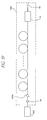
- Figure 14 illustrates an additional embodiment of a waveform converter 400.
- the converter 400 is formed by placing an optical amplifier 402A between the first stage nonlinear medium (DSF) 72A and the input signal section 18 of the converter 70 illustrated in Figure 7.
- an optical pulse signal supplied to the input signal section 18 is increased in optical power by the optical amplifier 402A.
- the high-power optical pulse then propagates through an input port 404 to enter the optical transmission path comprised of the alternating optical fibers 72A-C, 74A-C of Figure 7 to undergo the nonlinear and dispersion effects such as those described above.
- the optical signal is then transmitted through an output port 406 on the last dispersive fiber, having been converted into an optical pulse having a reduced pulse width and a widened optical spectrum. From this pulse, spectral components in the desired wavelength range are selected by the wavelength selecting element 16.
- a specific example of a waveform converter built in accordance with Figure 14 is further described hereafter.
- the waveform converter 400 of Figure 14 can be implemented using, for example, 1550 nm band DSF's 72A-C, 1300 nm band SMF's 74A-C, and an erbium doped optical fiber amplifier (EDFA) 402A.
- a beat light signal having a wavelength of approximately 1550 nm can be supplied to the input signal section 18 where it is amplified by the EDFA 402A.
- Figure 15A illustrates an autocorrelation trace 500 of the amplified signal
- Figure 15B illustrates an optical spectrum of the amplified signal that is supplied to the nonlinear medium input section 404.
- the optical pulses of the amplified signal have a pulse period of approximately 100 GHz, a pulse autocorrelation at full-width, half-maximum (FWHM) of approximately 3 ps, and a center wavelength of approximately 1560 nm.
- the amplified optical signal is then transmitted through the nonlinear medium and dispersion medium optical transmission path, and the signal produced at the dispersion medium output section 406 is illustrated in the autocorrelation graph of Figure 16A and the optical spectrum graph of Figure 16B.
- the optical pulses supplied to the transmission path were compressed as shown by the autocorrelation FWHM reduction from 3 ps to 0.46 ps, and the optical spectrum was substantially widened.
- the optical signal is then transmitted through the wavelength selecting element 16, where a center wavelength of 1550 nm can be selected.
- the signal produced from the wavelength selecting element 16 has an autocorreleation as illustrated in Figure 17A, and an optical spectrum as illustrated in Figure 17B.
- the optical spectrum shown in Figure 17B illustrates the new center frequency of 1550 nm for the optical signal.
- the wavelength selecting element 16 can effectively remove amplified spontaneous emission (ASE) noise which was generated by the optical amplifier 402A. This reduction in noise can be seen by comparing the optical spectrum of Figure 17B with that of Figures 15B and 16B.
- ASE amplified spontaneous emission
- the waveform converter 400 of Figure 14 is therefore not only capable of reducing the pulse width of an optical signal, but also optimizing transmitted optical pulses by selecting spectral components in the desired wavelength and removing noise components.
- Figure 18 illustrates an additional embodiment of a waveform converter 800.
- the converter 800 can be formed by placing the wavelength selecting element 16 between the second-stage SMF 74B and the third-stage DSF 72C, and by placing a second optical amplifier 402B immediately before the output signal section 20 of the converter 400 from Figure 15.
- spectral components in the desired wavelength range are selected from an optical pulse by the wavelength selecting element 16 after the pulse width has been reduced and the optical spectrum widened by the first and second stage DSF and SMF elements 72A-B, 74A-B.
- the optical pulse width can be further reduced along with widening of the optical spectrum by the third-stage DSF and SMF elements 72C, 74C.
- the resulting optical pulse can then be amplified by the second amplifier 402B, and provided to the output signal section 20 as a high-power optical pulse.
- Figure 19 illustrates one embodiment of an optical pulse light source 900.
- the optical pulse light source 900 can be formed by connecting a modulated signal light source 902 for generating periodically intensity modulated optical pulses to the input signal section 18 of the converter 400 shown in Figure 15.
- the modulated signal can be generated by, for example, a direct modulation method in which a laser diode is used as a light source and a light source drive current is modulated, an external intensity modulator, or a method in which optical pulses from two light sources having different wavelengths are combined to affect modulation by beating between the wavelengths.
- Modulated optical pulses obtained from the modulated signal light source 902 can then be converted by waveform shaping elements of the converter 400 into optical pulses having the desired optical spectrum and pulse duration.
- the dispersion medium and nonlinear medium are not limited to the described optical fibers.
- the dispersion medium may be implemented using, for example, a photonic crystal.
- the nonlinear medium may be implemented by, for example, optical waveguides having high nonlinearity, nonlinear optical crystals, or photonic crystal materials such as chalcogenida fibers. These devices or materials may have a dispersion effect as well as a nonlinear effect.
- the wavelength selecting element may be implemented using such devices as a bandpass filter or a Fabry-Perot interferometer having a periodic structure.
- every one of the optical components may have a polarization-maintaining characteristic.
- a polarization-maintaining filter may be inserted in the DSF 52.
- the light source 902 and polarization-maintaining optical amplifier 402A may have such a characteristic as to produce a constant polarization output.
Landscapes
- Physics & Mathematics (AREA)
- Electromagnetism (AREA)
- Engineering & Computer Science (AREA)
- Computer Networks & Wireless Communication (AREA)
- Signal Processing (AREA)
- Chemical & Material Sciences (AREA)
- Dispersion Chemistry (AREA)
- Optics & Photonics (AREA)
- Nonlinear Science (AREA)
- General Physics & Mathematics (AREA)
- Optical Modulation, Optical Deflection, Nonlinear Optics, Optical Demodulation, Optical Logic Elements (AREA)
- Optical Communication System (AREA)
Applications Claiming Priority (2)
| Application Number | Priority Date | Filing Date | Title |
|---|---|---|---|
| JP2001022220A JP2002229080A (ja) | 2001-01-30 | 2001-01-30 | 光パルス波形変換器、それを備えた光パルス光源 |
| JP2001022220 | 2001-01-30 |
Publications (2)
| Publication Number | Publication Date |
|---|---|
| EP1237304A2 true EP1237304A2 (de) | 2002-09-04 |
| EP1237304A3 EP1237304A3 (de) | 2003-11-05 |
Family
ID=18887666
Family Applications (1)
| Application Number | Title | Priority Date | Filing Date |
|---|---|---|---|
| EP02002297A Withdrawn EP1237304A3 (de) | 2001-01-30 | 2002-01-30 | Optischer Pulsformer |
Country Status (4)
| Country | Link |
|---|---|
| US (1) | US6892015B2 (de) |
| EP (1) | EP1237304A3 (de) |
| JP (1) | JP2002229080A (de) |
| CA (1) | CA2369525A1 (de) |
Cited By (2)
| Publication number | Priority date | Publication date | Assignee | Title |
|---|---|---|---|---|
| WO2004049054A1 (ja) * | 2002-11-21 | 2004-06-10 | The Furukawa Electric Co., Ltd. | 光伝送システムにおける光源、波形整形器、光パルス列発生装置、及び 光再生システム |
| CN100380225C (zh) * | 2002-11-21 | 2008-04-09 | 古河电气工业株式会社 | 光脉冲串发生装置 |
Families Citing this family (13)
| Publication number | Priority date | Publication date | Assignee | Title |
|---|---|---|---|---|
| JP4532061B2 (ja) * | 2002-09-24 | 2010-08-25 | 古河電気工業株式会社 | 波形整形器、光パルス発生装置および光再生システム |
| US7483608B2 (en) | 2004-03-19 | 2009-01-27 | The Furukawa Electric Co., Ltd. | Method of designing optical pulse shaping device and optical pulse shaping device |
| GB2434483A (en) | 2006-01-20 | 2007-07-25 | Fianium Ltd | High-Power Short Optical Pulse Source |
| JP2008002815A (ja) * | 2006-06-20 | 2008-01-10 | Univ Nagoya | 波長変化パルス光発生装置およびこれを用いた光断層計測装置 |
| JP4438835B2 (ja) * | 2007-07-20 | 2010-03-24 | ソニー株式会社 | 高周波信号生成方法および高周波信号生成装置 |
| US8275263B1 (en) * | 2009-06-26 | 2012-09-25 | The Boeing Company | Multiplication of phase deviations |
| US8478134B2 (en) * | 2009-08-31 | 2013-07-02 | Ofs Fitel, Llc | Compression of generated optical continuum utilizing higher-order-mode fiber |
| WO2013039668A1 (en) | 2011-09-14 | 2013-03-21 | Fianium, Inc. | Methods and apparatus pertaining to picosecond pulsed fiber based lasers |
| US8447155B1 (en) | 2012-09-13 | 2013-05-21 | Ram Photonics, LLC | Methods and apparatus for power-equalized optical frequency comb generation |
| US10411810B2 (en) | 2016-07-04 | 2019-09-10 | The Regents Of The University Of California | Receiver with mutually coherent optical frequency combs |
| US10523329B2 (en) | 2016-11-07 | 2019-12-31 | The Regents Of The University Of California | Comb-assisted cyclostationary analysis |
| WO2019010439A1 (en) | 2017-07-07 | 2019-01-10 | The Regents Of The University Of California | SYSTEM AND METHOD FOR ENHANCING SENSITIVITY OF A RECEIVER |
| JP7661140B2 (ja) | 2021-06-11 | 2025-04-14 | 古河電気工業株式会社 | パルス光整形器およびパルス光発生器 |
Family Cites Families (14)
| Publication number | Priority date | Publication date | Assignee | Title |
|---|---|---|---|---|
| JP3419510B2 (ja) * | 1992-10-16 | 2003-06-23 | 富士通株式会社 | 波長分散を補償した光通信システム及び該システムに適用可能な位相共役光発生装置 |
| JPH0822038A (ja) * | 1994-07-08 | 1996-01-23 | Sumitomo Electric Ind Ltd | 位相共役光発生器 |
| JPH0829815A (ja) * | 1994-07-20 | 1996-02-02 | Nippon Telegr & Teleph Corp <Ntt> | 白色超短パルス光源 |
| US5499134A (en) * | 1994-08-24 | 1996-03-12 | Imra America | Optical pulse amplification using chirped Bragg gratings |
| JPH08122833A (ja) * | 1994-10-18 | 1996-05-17 | Nippon Telegr & Teleph Corp <Ntt> | 波長変換装置 |
| US5530778A (en) * | 1995-02-23 | 1996-06-25 | The United States Of America As Represented By The Secretary Of The Navy | Direction finding apparatus using tunable fiber optic delay line |
| EP0732819A3 (de) | 1995-03-15 | 1998-03-11 | Sumitomo Electric Industries, Ltd. | Farbzerstreuungskompensator und farbstreuungskompensierendes optisches Übertragungssystem |
| GB9603911D0 (en) * | 1996-02-23 | 1996-04-24 | Univ Southampton | Dispersion compensation in optical fibre transmission |
| US6108474A (en) | 1997-12-11 | 2000-08-22 | Lucent Technologies Inc. | Optical pulse compressor for optical communications systems |
| US6330383B1 (en) * | 1998-02-20 | 2001-12-11 | University Of Southern California | Disperson compensation by using tunable nonlinearly-chirped gratings |
| US5982963A (en) * | 1997-12-15 | 1999-11-09 | University Of Southern California | Tunable nonlinearly chirped grating |
| JP3903235B2 (ja) * | 1998-12-18 | 2007-04-11 | 富士通株式会社 | 可変波長四光波混合器 |
| JP3567782B2 (ja) | 1999-03-09 | 2004-09-22 | Kddi株式会社 | 分散補償光伝送路及びシステム |
| JP4494557B2 (ja) * | 1999-03-29 | 2010-06-30 | 古河電気工業株式会社 | 四光子混合用光ファイバのファイバ長の決定方法 |
-
2001
- 2001-01-30 JP JP2001022220A patent/JP2002229080A/ja active Pending
-
2002
- 2002-01-23 US US10/057,733 patent/US6892015B2/en not_active Expired - Fee Related
- 2002-01-29 CA CA002369525A patent/CA2369525A1/en not_active Abandoned
- 2002-01-30 EP EP02002297A patent/EP1237304A3/de not_active Withdrawn
Cited By (4)
| Publication number | Priority date | Publication date | Assignee | Title |
|---|---|---|---|---|
| WO2004049054A1 (ja) * | 2002-11-21 | 2004-06-10 | The Furukawa Electric Co., Ltd. | 光伝送システムにおける光源、波形整形器、光パルス列発生装置、及び 光再生システム |
| CN100380225C (zh) * | 2002-11-21 | 2008-04-09 | 古河电气工业株式会社 | 光脉冲串发生装置 |
| US7447444B2 (en) | 2002-11-21 | 2008-11-04 | The Furukawa Electric Co., Ltd. | Light source in optical transmission system, waveform shaper, optical pulse train generator, and optical reproduction system |
| US7769298B2 (en) | 2002-11-21 | 2010-08-03 | The Furukawa Electric Co., Ltd. | Light source in optical transmission system, waveform shaper, optical pulse train generator and optical reproduction system |
Also Published As
| Publication number | Publication date |
|---|---|
| EP1237304A3 (de) | 2003-11-05 |
| US6892015B2 (en) | 2005-05-10 |
| CA2369525A1 (en) | 2002-07-30 |
| JP2002229080A (ja) | 2002-08-14 |
| US20020164135A1 (en) | 2002-11-07 |
Similar Documents
| Publication | Publication Date | Title |
|---|---|---|
| US7027468B2 (en) | Phase-insensitive recovery of clock pulses of wavelength division multiplexed optical signals | |
| US7076174B2 (en) | Method, device, and system for processing optical signal | |
| US6919986B2 (en) | Nonlinear polarization amplifiers in nonzero dispersion shifted fiber | |
| US7440167B2 (en) | Optical fiber for Raman amplification, optical fiber coil, Raman amplifier, and optical communication system | |
| KR100680682B1 (ko) | 비선형 사그낙 증폭기에 의한 이득 평탄화 | |
| Islam et al. | Fiber parametric amplifiers for wavelength band conversion | |
| US6892015B2 (en) | Optical pulse waveform conversion | |
| EP1227363B1 (de) | Nichtlinearer optischer Ringspiegel | |
| JP2009177641A (ja) | 光信号処理装置、光受信装置および光中継装置 | |
| US5754334A (en) | Device for and method of modifying the spectral characteristics of optical signals | |
| JPH09197449A (ja) | 光パルス発生装置 | |
| JP2000180907A (ja) | 可変波長四光波混合器 | |
| JP4041079B2 (ja) | スイープされた波長の広帯域ラマンポンプ源 | |
| JP2004287074A (ja) | 波長可変の光パルス発生装置 | |
| Li et al. | A dual-wavelength and dual-repetition-rate actively mode-locked fiber ring laser | |
| US7034988B2 (en) | Wavelength conversion device | |
| EP1394599B1 (de) | Wellenlängenumsetzer | |
| JP2001264830A (ja) | 多波長光源 | |
| JP3975202B2 (ja) | 光ファイバ及び光源装置 | |
| Provino et al. | Broadband and flat parametric gain with a single low-power pump in a multi-section fiber arrangement | |
| KR100326151B1 (ko) | 신호 대 잡음비 성능이 향상된 라만 광섬유 증폭기 및 그 사용방법 | |
| JP2005241732A (ja) | 光パルス増幅装置 | |
| JP2004037948A (ja) | 多波長光源および光通信システム | |
| JP2004037949A (ja) | 多波長光源 | |
| JP2007178681A (ja) | 多波長光源 |
Legal Events
| Date | Code | Title | Description |
|---|---|---|---|
| PUAI | Public reference made under article 153(3) epc to a published international application that has entered the european phase |
Free format text: ORIGINAL CODE: 0009012 |
|
| AK | Designated contracting states |
Kind code of ref document: A2 Designated state(s): AT BE CH CY DE DK ES FI FR GB GR IE IT LI LU MC NL PT SE TR |
|
| AX | Request for extension of the european patent |
Free format text: AL;LT;LV;MK;RO;SI |
|
| RIC1 | Information provided on ipc code assigned before grant |
Ipc: 7G 02F 1/35 B Ipc: 7H 01S 3/00 B Ipc: 7H 04B 10/18 B Ipc: 7G 02B 6/16 B Ipc: 7H 04B 10/12 A |
|
| PUAL | Search report despatched |
Free format text: ORIGINAL CODE: 0009013 |
|
| AK | Designated contracting states |
Kind code of ref document: A3 Designated state(s): AT BE CH CY DE DK ES FI FR GB GR IE IT LI LU MC NL PT SE TR |
|
| AX | Request for extension of the european patent |
Extension state: AL LT LV MK RO SI |
|
| 17P | Request for examination filed |
Effective date: 20040415 |
|
| AKX | Designation fees paid |
Designated state(s): DE FR GB IT |
|
| 17Q | First examination report despatched |
Effective date: 20051215 |
|
| STAA | Information on the status of an ep patent application or granted ep patent |
Free format text: STATUS: THE APPLICATION HAS BEEN WITHDRAWN |
|
| 18W | Application withdrawn |
Effective date: 20071114 |