EP0922992A2 - Optischer Pulskompressor für optische Kommunikationssysteme - Google Patents
Optischer Pulskompressor für optische Kommunikationssysteme Download PDFInfo
- Publication number
- EP0922992A2 EP0922992A2 EP98309842A EP98309842A EP0922992A2 EP 0922992 A2 EP0922992 A2 EP 0922992A2 EP 98309842 A EP98309842 A EP 98309842A EP 98309842 A EP98309842 A EP 98309842A EP 0922992 A2 EP0922992 A2 EP 0922992A2
- Authority
- EP
- European Patent Office
- Prior art keywords
- optical
- pulse
- section
- grating
- dispersion
- Prior art date
- Legal status (The legal status is an assumption and is not a legal conclusion. Google has not performed a legal analysis and makes no representation as to the accuracy of the status listed.)
- Granted
Links
- 230000003287 optical effect Effects 0.000 title claims abstract description 43
- 238000004891 communication Methods 0.000 title claims description 9
- 239000006185 dispersion Substances 0.000 claims abstract description 68
- 239000000835 fiber Substances 0.000 claims abstract description 54
- 230000000737 periodic effect Effects 0.000 claims abstract description 9
- 230000005540 biological transmission Effects 0.000 claims description 5
- 239000005387 chalcogenide glass Substances 0.000 claims description 2
- 230000006835 compression Effects 0.000 abstract description 38
- 238000007906 compression Methods 0.000 abstract description 38
- 230000009021 linear effect Effects 0.000 abstract description 19
- 238000000034 method Methods 0.000 abstract description 12
- 239000013307 optical fiber Substances 0.000 abstract description 5
- 230000008569 process Effects 0.000 abstract description 3
- 230000009467 reduction Effects 0.000 abstract description 3
- 150000004770 chalcogenides Chemical class 0.000 abstract description 2
- 230000002939 deleterious effect Effects 0.000 abstract description 2
- 230000003595 spectral effect Effects 0.000 description 14
- 238000001228 spectrum Methods 0.000 description 14
- 238000001069 Raman spectroscopy Methods 0.000 description 7
- 230000000694 effects Effects 0.000 description 6
- 238000013461 design Methods 0.000 description 5
- 239000000463 material Substances 0.000 description 5
- 230000001419 dependent effect Effects 0.000 description 4
- 230000002547 anomalous effect Effects 0.000 description 3
- 230000001627 detrimental effect Effects 0.000 description 3
- 230000001902 propagating effect Effects 0.000 description 3
- 238000004088 simulation Methods 0.000 description 3
- VYPSYNLAJGMNEJ-UHFFFAOYSA-N Silicium dioxide Chemical compound O=[Si]=O VYPSYNLAJGMNEJ-UHFFFAOYSA-N 0.000 description 2
- 230000003993 interaction Effects 0.000 description 2
- 238000013178 mathematical model Methods 0.000 description 2
- 230000004044 response Effects 0.000 description 2
- 239000004065 semiconductor Substances 0.000 description 2
- 238000007493 shaping process Methods 0.000 description 2
- 230000005374 Kerr effect Effects 0.000 description 1
- 230000005699 Stark effect Effects 0.000 description 1
- 238000004458 analytical method Methods 0.000 description 1
- 238000013459 approach Methods 0.000 description 1
- 238000004364 calculation method Methods 0.000 description 1
- 238000005253 cladding Methods 0.000 description 1
- 230000002301 combined effect Effects 0.000 description 1
- 230000008878 coupling Effects 0.000 description 1
- 238000010168 coupling process Methods 0.000 description 1
- 238000005859 coupling reaction Methods 0.000 description 1
- 238000010586 diagram Methods 0.000 description 1
- 238000002474 experimental method Methods 0.000 description 1
- 230000009022 nonlinear effect Effects 0.000 description 1
- 230000010363 phase shift Effects 0.000 description 1
- 230000005855 radiation Effects 0.000 description 1
- 239000000377 silicon dioxide Substances 0.000 description 1
Images


Classifications
-
- G—PHYSICS
- G02—OPTICS
- G02F—OPTICAL DEVICES OR ARRANGEMENTS FOR THE CONTROL OF LIGHT BY MODIFICATION OF THE OPTICAL PROPERTIES OF THE MEDIA OF THE ELEMENTS INVOLVED THEREIN; NON-LINEAR OPTICS; FREQUENCY-CHANGING OF LIGHT; OPTICAL LOGIC ELEMENTS; OPTICAL ANALOGUE/DIGITAL CONVERTERS
- G02F1/00—Devices or arrangements for the control of the intensity, colour, phase, polarisation or direction of light arriving from an independent light source, e.g. switching, gating or modulating; Non-linear optics
- G02F1/35—Non-linear optics
- G02F1/365—Non-linear optics in an optical waveguide structure
-
- H—ELECTRICITY
- H01—ELECTRIC ELEMENTS
- H01S—DEVICES USING THE PROCESS OF LIGHT AMPLIFICATION BY STIMULATED EMISSION OF RADIATION [LASER] TO AMPLIFY OR GENERATE LIGHT; DEVICES USING STIMULATED EMISSION OF ELECTROMAGNETIC RADIATION IN WAVE RANGES OTHER THAN OPTICAL
- H01S3/00—Lasers, i.e. devices using stimulated emission of electromagnetic radiation in the infrared, visible or ultraviolet wave range
- H01S3/005—Optical devices external to the laser cavity, specially adapted for lasers, e.g. for homogenisation of the beam or for manipulating laser pulses, e.g. pulse shaping
- H01S3/0057—Temporal shaping, e.g. pulse compression, frequency chirping
Definitions
- This invention relates an optical pulse compressor particularly useful in time domain multiplexed optical communications systems.
- a multiplicity of low bit rate binary optical pulse data streams are interleaved to form a single high bit rate data stream.
- the duty cycle of the pulses on the low bit rate streams must be small.
- a low bit rate stream may have a bit rate of 10 Gbits/s. This provides a time slot for each pulse of 100 ps. The pulse must be shorter than 100 ps. But if one wishes to interleave 10 such streams into a 100 Gbits/s system, then ten pulses must be fit into a 100ps. Such short pulses cannot typically be obtained by the use of high speed electronics and conventional sources such as electroabsorbtion modulated lasers (EMLs).
- EMLs electroabsorbtion modulated lasers
- Nonlinear optical pulse compressors typically comprise a source of optical pulses, a length of nonlinear optical fiber having positive dispersive properties (positive group velocity dispersion) and a negative dispersion component such as a grating pair or a prism pair.
- the nonlinearity increases the spectral bandwidth of the pulse which is chirped by the positive dispersion, and the subsequent negative dispersion component compresses the duration of the pulse to a bandwidth limited pulse.
- an optical pulse compressor comprises a pulse source, a section of nonlinear optical waveguide including a periodic structure, such as Bragg grating, for providing positive dispersion and a section of linear optical waveguide including a negative dispersion component.
- the nonlinear waveguide should have a second order index N 2 at least ten times the second order index N 2 ' of the linear waveguide.
- the nonlinear waveguide is preferably chalcogenide fiber, with a Bragg grating in the core. Because the grating is several orders of magnitude more dispersive than standard optical fiber, the length of the nonlinear waveguide section can be scaled down to a few centimeters with accompanying reduction of deleterious processes. Modeling suggests that compression factors of 5 with an initial 60 ps pulse are achievable with grating lengths of about 20 cm.
- Part I describes the structural features of the pulse compressor and an optical communications systems using it.
- Part II describes the theory underlying the invention and presents a mathematical model of its operation.
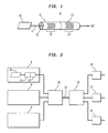
- Fig. 1 is a schematic illustration of an optical pulse compressor 9 comprising a pulse source 10 of center wavelength ⁇ , a first section of nonlinear waveguide 11 including a periodic structure 12 such as a Bragg grating for providing positive dispersion to the pulses and a second section of linear waveguide 13 including a negative dispersion component 14.
- the pulse source 10 is preferably a mode-locked laser or a semiconductor laser chosen and adapted to provide a transform limited pulse. Such a pulse has minimal spectral content for its width and typically cannot be further compressed without increasing its spectral bandwidth.
- the preferred center wavelength ⁇ is about 1.55 ⁇ m.
- the nonlinear section 11 preferably comprises a length of optical fiber into which a Bragg grating 12 has been formed as by UV radiation.
- the fiber preferably has a core 15 of material, such as chalcogenide glass, having nonlinear optical properties as compared with the second section.
- the first section should have a core with a second order index N 2 at least ten times that of the second order index N 2 ' of the second section.
- the length of the waveguide is typically less than 500 cm.
- the grating 12 is preferably an apodized grating having a region of steep positive dispersion for light of wavelength ⁇ (close to the bandgap on the long wavelength side of the grating).
- Alternative periodic structures for achieving dispersion include periodic photonic bandgap structures or periodic perturbations in the fiber cladding.
- the linear waveguide 13 can be conventional transmission fiber and can be coupled to any negative dispersion component 14, such as a prism for providing negative dispersion.
- the component 14 is a grating.
- the waveguide is ideally a fiber with a core (not shown) of material, such as silica, having linear optical properties.
- the negative dispersion component 14 is an apodized Bragg grating having a region of steep negative dispersion for light of wavelength ⁇ (the short wavelength side of the grating).
- transform-limited pulses from source 10 enter the first section waveguide 11 where they propagate through grating 12 with high positive dispersion.
- the output of the first section is a pulse with greater duration and a greater spectral content.
- the wider spectrum pulse enters the negative dispersion section 13 and incurs chirp compensation which rearranges the spectral components to produce a substantially shorter pulse.
- Fig 2 schematically illustrates an optical communications system using the pulse compressor of Fig. 1.
- the system comprises a plurality of pulse compressors 9, a time division multiplexer 20, and a transmission fiber 21 for transmitting a plurality of time multiplexed signal channels.
- a time division demultiplexer 22 At the receiving end of fiber 21 is a time division demultiplexer 22 for presenting one or more of the transmitted channels to respective receivers 23.
- the compressors 9 are as described in Fig. 1.
- the remaining components are conventional and well known.
- each transmitter launches a channel comprising a sequence of low bit rate, high duty cycle pulses into a respective dispersion section 11, 12 of a compressor.
- the resulting low bit rate, low duty cycle pulses are combined (interleaved) by multiplexer 20, and transmitted as a high bit rate time multiplexed stream on fiber 21.
- a demultiplexer 22 one or more of the transmitted channels can be separated for reception by receivers 23.
- Short pulse propagation in optical fiber in the near infrared (IR) spectral region is governed mainly by self-phase modulation (SPM) via the Kerr effect and group velocity dispersion (GVD).
- SPM self-phase modulation
- VGD group velocity dispersion
- the relative strength of these effects is typically given by a character-istic length scale - namely the dispersion length L D .
- ⁇ 0 is the full width at half maximum (FWHM) pulse width
- s 2 is a numerical factor which depends on the pulse shape (2.77 for Gaussian and 3.11 for hyperbolic secant)
- ⁇ is the wavelength
- a eff is the effective mode area
- n 2 is the nonlinear index
- P is the peak power of the pulse.
- L D is proportional to ⁇ 2 / 0 and L NL is proportional to ⁇ 0 (for fixed pulse energy) the ideal length L of the fiber scales as ⁇ 3/2 / 0, i.e., longer pulses require longer lengths of fiber for efficient compression.
- the intrinsic fiber dispersion in standard fiber is very small (usually on the order of 10 ps 2 /km in the IR region) leading to very long dispersion lengths. This implies that for long input pulses propagating in a standard fiber compressor, the fiber will have to be very long for ideal compression. In this case the peak power has to be scaled down to avoid exceeding the threshold for stimulated Raman Scattering, which is detrimental to compression.
- the dispersion length is approximately 5 km.
- the nonlinear length is approximately 0.5 m and in this case the Raman threshold is exceeded and a good compressor is not feasible. Therefore, in order to observe nonlinear pulse shaping for pulsewidths on the order of 10-100 picoseconds (e.g. from modelocked Nd:YAG or semiconductor lasers), in short lengths of fiber, a highly dispersive fiber element is required. Such an element is a fiber grating, where the wavelength of operation is just outside the stopband (photonic gap).
- Fiber gratings have very large GVD close to the grating stopband. This is a direct consequence of the Kramers-Krönig relations: since the grating constitutes a sharp resonance, it is accompanied by strong dispersion. Viewed in another way, the multiple reflections in the grating introduce a time delay that is highly frequency-dependent. By operating just outside the stopband, the grating is used in transmission (the passband) and by apodizing the grating the ripples in the amplitude response can be eliminated. In typical fiber gratings the GVD can be up to six orders of magnitudes larger than the plain fiber GVD. This very high dispersion is limited to approximately the bandwidth of the stopband.
- GVD The increase in GVD reduces the dispersion length from tens of km to a few centimeters.
- efficient pulse compression of picosecond pulses may be achieved by using very short lengths of fiber with appropriate fiber gratings to produce square pulses with linear chirp across them. These pulses may then be compressed using a linear system with anomalous GVD such as a prism pair, grating pair or fiber grating device.
- Pulse compression is typically achieved in one of two ways: soliton compression or 2) fiber-grating or fiber-prism compression.
- soliton compression is usually preferred since it yields cleaner compressed pulses, whereas soliton compression is typically accompanied by pedestals on the compressed pulse.
- a fiber with positive dispersion is used to broaden the pulse spectrum and to generate a square intensity profile with very linear chirp across the pulse.
- SPM generates new frequencies and broadens the pulse spectrum and the GVD linearizes the chirp and "squares" the pulse.
- the linear chirp can then be compensated by a negative dispersive element (such as a grating pair, prism pair or a chirped fiber grating operating in reflection), producing a nearly transform-limited compressed pulse.
- a negative dispersive element such as a grating pair, prism pair or a chirped fiber grating operating in reflection
- the pulse compression technique is governed by two important parameters:
- an anomalous dispersion element typically a grating pair or prism pair, both of which have very small higher order dispersion and no associated nonlinearity.
- a fiber grating may be used since it has opposite sign GVD on the two sides of the stopband. It should be emphasized that the nonlinear part of the compressor gives these ideal results when only GVD and SPM are present, i.e., when there is no higher order dispersion or higher order nonlinearities.
- the linear section of the compressor ideally has only negative GVD.
- SRS stimulated Raman scattering
- This compression factor can be much less than the compression achieved with the optimum fiber length.
- ⁇ (n/c) ( ⁇ - ⁇ B ) is the detuning parameter with ⁇ B , the Bragg frequency.
- the detuning is positive on the short wavelength side and negative on the long wavelength, where the GVD is positive. Since we are considering only positive GVD the detuning will always be negative. To avoid confusion in the following discussion we will deal with the absolute value of ⁇ rather than ⁇ itself.
- a reasonable M value is therefore ⁇ 0.05.
- the general design criteria for pulse compression are limited by two factors: the peak intensity and the higher order dispersion.
- High peak intensity is detrimental because it leads to 1) SRS, 2) shifting of the Bragg resonance (similar to the optical Stark effect) and to an intensity-dependent dispersion close to the stopband, and 3) truncation of the initial pulse spectrum which gets broadened by SPM: if the broadening is larger than the detuning parameter the spectrum will get "clipped" by the grating.
- higher order dispersion leads to pulse distortion as shown earlier. However if this higher order dispersion is also compensated by the compensating section, this may not be a problem.
- the threshold for SRS dictates an upper limit on the product of peak power and fiber length as follows: g R PL eff A eeff ⁇ 16 ⁇ PL ⁇ 16 A eff g R where g R , is the Raman gain coefficient at the wavelength of operation and L eff is the effective length limited by loss. In our case the lengths of interest are such that L eff ⁇ L. This leads to a lower limit on the nonlinear length defined in eqn. (1): L NL > g R ⁇ 32 ⁇ n 2 L
- the limit expressed in (8) is a general limit for this type of compressor and therefore is not related to the grating parameters.
- the next two limits to be discussed are specific to fiber gratings: 1) an intensity-dependent shift of the Bragg resonance leading to nonlinear dispersion. As is shown in the appendix, for ⁇ ⁇ ⁇ 0 , L NL ⁇ 0 ⁇ 1 I is required to minimize this effect (here ⁇ o , is the low intensity detuning parameter).
- the last limitation imposed by the peak intensity is due to SPM induced spectral broadening of the input pulse spectrum. This broadening will be approximately F c , since this is the intended purpose of the compressor. We now have to insure that this spectrum does not overlap the reflection spectrum of the grating, since this would cause the spectrum to be clipped.
- the SRS-imposed limit is the strictest one since it involves only material parameters and the wavelength of operation (the other intensity-dependent limitations may be avoided by careful grating design).
- the compression factor is given approximately by 1+0.6N 2 (L/L D ) rather than N/ 1.6.
- F c we can finally write an absolute upper limit for the compression ratio:
- the Raman threshold for a 60 ps pulse at 1.06 ⁇ m propagating through 10 meters of fiber is about 1 kW, so for grating lengths of up to 1 meter an input peak power of 10 kW may be used.
- L D 64 cm
- L NL 207.4 (with a corresponding GVD of 6.3 ps/cm) and an optimum length of 63.5 cm.
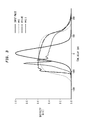
- FIG. 5A and 5B compares the results of the two different simulation methods using the same parameters but with a grating length of 20 cm.
- Figure 5(a) shows the intensity profile of the pulse before the dispersion compensating section and 5(b) shows the resulting compressed pulse at the output of the system with a compression factor of 4.6.
- the grating may be viewed as an effective homogenous nonlinear dispersive medium to which the nonlinear Schrodinger (NLS) equation may be applied.
- NLS nonlinear Schrodinger
Landscapes
- Physics & Mathematics (AREA)
- Nonlinear Science (AREA)
- General Physics & Mathematics (AREA)
- Optics & Photonics (AREA)
- Optical Modulation, Optical Deflection, Nonlinear Optics, Optical Demodulation, Optical Logic Elements (AREA)
- Optical Communication System (AREA)
- Optical Fibers, Optical Fiber Cores, And Optical Fiber Bundles (AREA)
Applications Claiming Priority (2)
| Application Number | Priority Date | Filing Date | Title |
|---|---|---|---|
| US08/989,093 US6108474A (en) | 1997-12-11 | 1997-12-11 | Optical pulse compressor for optical communications systems |
| US989093 | 1997-12-11 |
Publications (3)
| Publication Number | Publication Date |
|---|---|
| EP0922992A2 true EP0922992A2 (de) | 1999-06-16 |
| EP0922992A3 EP0922992A3 (de) | 2001-04-25 |
| EP0922992B1 EP0922992B1 (de) | 2004-08-04 |
Family
ID=25534746
Family Applications (1)
| Application Number | Title | Priority Date | Filing Date |
|---|---|---|---|
| EP98309842A Expired - Lifetime EP0922992B1 (de) | 1997-12-11 | 1998-12-01 | Optischer Pulskompressor für optische Kommunikationssysteme |
Country Status (4)
| Country | Link |
|---|---|
| US (1) | US6108474A (de) |
| EP (1) | EP0922992B1 (de) |
| JP (1) | JP3404305B2 (de) |
| DE (1) | DE69825401T2 (de) |
Cited By (10)
| Publication number | Priority date | Publication date | Assignee | Title |
|---|---|---|---|---|
| WO2001082508A1 (en) * | 2000-04-18 | 2001-11-01 | Roke Manor Research Limited | Improved data compression apparatus and method therefor |
| WO2001086344A1 (en) * | 2000-05-08 | 2001-11-15 | Imra America, Inc. | Parabolic pulse communication system and method |
| WO2002075980A1 (en) * | 2001-03-16 | 2002-09-26 | Roke Manor Research Limited | Optical data compression device and method |
| GB2376142A (en) * | 2001-03-16 | 2002-12-04 | Roke Manor Research | Multiplexing compressed optical data pulses |
| EP1237304A3 (de) * | 2001-01-30 | 2003-11-05 | The Furukawa Electric Co., Ltd. | Optischer Pulsformer |
| WO2003098342A1 (en) * | 2002-05-14 | 2003-11-27 | Corning Incorporated | Microstructured optical waveguide having large optical nonlinearity |
| WO2005024482A1 (de) * | 2003-09-05 | 2005-03-17 | Leica Microsystems Cms Gmbh | Lichtquelle mit einem mikrostrukturierten optischen element |
| EP1815281A4 (de) * | 2004-11-22 | 2009-05-06 | Imra America Inc | Gechirpte impulsverstärkungssysteme ganz in faser |
| DE10115589B4 (de) | 2000-06-17 | 2020-07-30 | Leica Microsystems Cms Gmbh | Konfokales Scanmikroskop |
| US20210384692A1 (en) * | 2018-10-26 | 2021-12-09 | The Government Of The United States Of America, As Represented By The Secretary Of The Navy | Apparatus And Method For Tunable Frequency Parametric Down Conversion Of High Peak Power Lasers Through Dual Chirp Pulse Mixing |
Families Citing this family (35)
| Publication number | Priority date | Publication date | Assignee | Title |
|---|---|---|---|---|
| GB9917880D0 (en) * | 1999-07-30 | 1999-09-29 | Roke Manor Research | Fast data modulator |
| JP3784585B2 (ja) * | 1999-08-26 | 2006-06-14 | 富士通株式会社 | 光ファイバ伝送のための方法、光デバイス及びシステム |
| US6650466B1 (en) * | 1999-08-27 | 2003-11-18 | Frank Wise | High-energy pulse compression using phase shifts produced by the cascade quadriatic nonlinearity |
| US6208792B1 (en) * | 1999-09-20 | 2001-03-27 | Lucent Technologies Inc. | Article comprising a planar optical waveguide with optically non-linear core |
| US7173551B2 (en) | 2000-12-21 | 2007-02-06 | Quellan, Inc. | Increasing data throughput in optical fiber transmission systems |
| US7307569B2 (en) | 2001-03-29 | 2007-12-11 | Quellan, Inc. | Increasing data throughput in optical fiber transmission systems |
| US7149256B2 (en) | 2001-03-29 | 2006-12-12 | Quellan, Inc. | Multilevel pulse position modulation for efficient fiber optic communication |
| DE60238602D1 (de) | 2001-04-04 | 2011-01-27 | Quellan Inc | Verfahren und system zum decodieren von mehrpegelsignalen |
| CN1520526A (zh) * | 2001-04-12 | 2004-08-11 | �ź㴫 | 高折射率差纤维波导及其应用 |
| US7160746B2 (en) * | 2001-07-27 | 2007-01-09 | Lightwave Microsystems Corporation | GeBPSG top clad for a planar lightwave circuit |
| WO2003071731A1 (en) | 2002-02-15 | 2003-08-28 | Quellan, Inc. | Multi-level signal clock recovery technique |
| AU2003217947A1 (en) | 2002-03-08 | 2003-09-22 | Quellan, Inc. | High speed analog-to-digital converter using a unique gray code having minimal bit transitions |
| US7245801B2 (en) * | 2002-03-21 | 2007-07-17 | University Of Rochester | Apparatus with a series of resonator structures situated near an optical waveguide for manipulating optical pulses |
| US7362976B2 (en) * | 2002-08-22 | 2008-04-22 | Main Street Ventures Llc | Generating of high rate modulated pulse streams |
| AU2003256569A1 (en) | 2002-07-15 | 2004-02-02 | Quellan, Inc. | Adaptive noise filtering and equalization |
| US20040057735A1 (en) * | 2002-09-23 | 2004-03-25 | Katsumi Uesaka | Optical transmitter using highly nonlinear fiber and method |
| US20040067065A1 (en) * | 2002-10-03 | 2004-04-08 | Innovation Core Sei, Inc. | Optical transmitter using nonlinear material and method |
| US20040067066A1 (en) * | 2002-10-03 | 2004-04-08 | Innovation Core Sei, Inc. | Optical transmission system using nonlinear material |
| US7079737B1 (en) * | 2002-10-11 | 2006-07-18 | Corning Incorporated | Devices and methods for dynamic dispersion compensation |
| AU2003287628A1 (en) | 2002-11-12 | 2004-06-03 | Quellan, Inc. | High-speed analog-to-digital conversion with improved robustness to timing uncertainty |
| CA2504951A1 (en) * | 2002-11-22 | 2004-06-10 | Omniguide Communications Inc. | Dielectric waveguide and method of making the same |
| US7277617B2 (en) * | 2003-05-07 | 2007-10-02 | Intel Corporation | Optical pulse compressor based on integrated planar lightwave circuit: method, device, and systems |
| US7050388B2 (en) | 2003-08-07 | 2006-05-23 | Quellan, Inc. | Method and system for crosstalk cancellation |
| US7804760B2 (en) | 2003-08-07 | 2010-09-28 | Quellan, Inc. | Method and system for signal emulation |
| ATE488068T1 (de) | 2003-11-17 | 2010-11-15 | Quellan Inc | Verfahren und system zur löschung von antennenstörungen |
| US7616700B2 (en) | 2003-12-22 | 2009-11-10 | Quellan, Inc. | Method and system for slicing a communication signal |
| JP2006166162A (ja) * | 2004-12-09 | 2006-06-22 | Nec Corp | パルス波形整形機能を有する通信システムおよび通信方法 |
| US7725079B2 (en) | 2004-12-14 | 2010-05-25 | Quellan, Inc. | Method and system for automatic control in an interference cancellation device |
| US7522883B2 (en) | 2004-12-14 | 2009-04-21 | Quellan, Inc. | Method and system for reducing signal interference |
| JP4816063B2 (ja) * | 2005-12-20 | 2011-11-16 | 住友電気工業株式会社 | 広帯域光源 |
| JP5078991B2 (ja) | 2006-04-26 | 2012-11-21 | ケラン エルエルシー | 通信チャネルからの放射性放出を削減する方法とシステム |
| WO2008151384A1 (en) * | 2007-06-14 | 2008-12-18 | The University Of Sydney | Optical signal to noise monitor |
| JP4760820B2 (ja) * | 2007-12-07 | 2011-08-31 | 沖電気工業株式会社 | 光パルス信号生成装置、光パルス信号生成方法、光符号分割多重送受信システム、及び光符号分割多重送受信方法 |
| US8730570B2 (en) * | 2009-07-01 | 2014-05-20 | Calmar Optcom, Inc. | Optical pulse compressing based on chirped fiber bragg gratings for pulse amplification and fiber lasers |
| DE102010052085A1 (de) | 2010-11-16 | 2012-05-16 | Ayhan Demircan | Photonisches Bauelement zur rein-optischen Kontrolle und Manipulation von optischen Impulsen |
Family Cites Families (8)
| Publication number | Priority date | Publication date | Assignee | Title |
|---|---|---|---|---|
| US3801937A (en) * | 1973-02-20 | 1974-04-02 | Hughes Aircraft Co | Acoustic pulse compression weighting filter transducer |
| US4588957A (en) * | 1982-06-09 | 1986-05-13 | International Business Machines Corporation | Optical pulse compression apparatus and method |
| US5136677A (en) * | 1989-12-21 | 1992-08-04 | Galileo Electro-Optics Corporation | Photorefractive effect in bulk chalcogenide glass and devices made therefrom |
| US5035481A (en) * | 1990-08-23 | 1991-07-30 | At&T Bell Laboratories | Long distance soliton lightwave communication system |
| US5148510A (en) * | 1990-11-28 | 1992-09-15 | Corning Incorporated | Optical fiber made of galliobismuthate glasses and optical devices using same |
| US5400350A (en) * | 1994-03-31 | 1995-03-21 | Imra America, Inc. | Method and apparatus for generating high energy ultrashort pulses |
| US5499134A (en) * | 1994-08-24 | 1996-03-12 | Imra America | Optical pulse amplification using chirped Bragg gratings |
| US5717799A (en) * | 1996-10-10 | 1998-02-10 | Northern Telecom Limited | Optical waveguide filters |
-
1997
- 1997-12-11 US US08/989,093 patent/US6108474A/en not_active Expired - Lifetime
-
1998
- 1998-12-01 EP EP98309842A patent/EP0922992B1/de not_active Expired - Lifetime
- 1998-12-01 DE DE69825401T patent/DE69825401T2/de not_active Expired - Lifetime
- 1998-12-07 JP JP34739498A patent/JP3404305B2/ja not_active Expired - Fee Related
Cited By (16)
| Publication number | Priority date | Publication date | Assignee | Title |
|---|---|---|---|---|
| WO2001082508A1 (en) * | 2000-04-18 | 2001-11-01 | Roke Manor Research Limited | Improved data compression apparatus and method therefor |
| WO2001086344A1 (en) * | 2000-05-08 | 2001-11-15 | Imra America, Inc. | Parabolic pulse communication system and method |
| DE10115589B4 (de) | 2000-06-17 | 2020-07-30 | Leica Microsystems Cms Gmbh | Konfokales Scanmikroskop |
| US6892015B2 (en) | 2001-01-30 | 2005-05-10 | The Furukawa Electric Company, Ltd. | Optical pulse waveform conversion |
| EP1237304A3 (de) * | 2001-01-30 | 2003-11-05 | The Furukawa Electric Co., Ltd. | Optischer Pulsformer |
| WO2002075980A1 (en) * | 2001-03-16 | 2002-09-26 | Roke Manor Research Limited | Optical data compression device and method |
| GB2376142A (en) * | 2001-03-16 | 2002-12-04 | Roke Manor Research | Multiplexing compressed optical data pulses |
| GB2376142B (en) * | 2001-03-16 | 2004-06-16 | Roke Manor Research | Data compression device and method |
| AU2002235944B2 (en) * | 2001-03-16 | 2004-08-19 | Roke Manor Research Limited | Optical data compression device and method |
| US6788862B2 (en) | 2002-05-14 | 2004-09-07 | Corning, Inc. | Microstructured optical waveguide having large optical nonlinearity |
| WO2003098342A1 (en) * | 2002-05-14 | 2003-11-27 | Corning Incorporated | Microstructured optical waveguide having large optical nonlinearity |
| WO2005024482A1 (de) * | 2003-09-05 | 2005-03-17 | Leica Microsystems Cms Gmbh | Lichtquelle mit einem mikrostrukturierten optischen element |
| US7466885B2 (en) | 2003-09-05 | 2008-12-16 | Leica Microsystems Cms Gmbh | Light source comprising a plurality of microstructured optical elements |
| EP1815281A4 (de) * | 2004-11-22 | 2009-05-06 | Imra America Inc | Gechirpte impulsverstärkungssysteme ganz in faser |
| US20210384692A1 (en) * | 2018-10-26 | 2021-12-09 | The Government Of The United States Of America, As Represented By The Secretary Of The Navy | Apparatus And Method For Tunable Frequency Parametric Down Conversion Of High Peak Power Lasers Through Dual Chirp Pulse Mixing |
| US12080984B2 (en) * | 2018-10-26 | 2024-09-03 | The Government Of The United States Of America, As Represented By The Secretary Of The Navy | Apparatus and method for tunable frequency parametric down conversion of high peak power lasers through dual chirp pulse mixing |
Also Published As
| Publication number | Publication date |
|---|---|
| DE69825401D1 (de) | 2004-09-09 |
| EP0922992B1 (de) | 2004-08-04 |
| DE69825401T2 (de) | 2005-08-11 |
| EP0922992A3 (de) | 2001-04-25 |
| JP3404305B2 (ja) | 2003-05-06 |
| JPH11242249A (ja) | 1999-09-07 |
| US6108474A (en) | 2000-08-22 |
Similar Documents
| Publication | Publication Date | Title |
|---|---|---|
| US6108474A (en) | Optical pulse compressor for optical communications systems | |
| EP0998067B1 (de) | Vorrichtung mit einem Pulskompressor | |
| Litchinitser et al. | Fiber Bragg gratings for dispersion compensation in transmission: theoretical model and design criteria for nearly ideal pulse recompression | |
| Lee et al. | Soliton self-frequency shift: experimental demonstrations and applications | |
| US6195484B1 (en) | Method and apparatus for arbitrary spectral shaping of an optical pulse | |
| Eggleton et al. | Modulational instability and tunable multiple soliton generation in apodized fiber gratings | |
| EP1617278A1 (de) | Optischer impulskomprimierer und optischer funktionsgenerator, verfahren zum komprimieren optischer impulse und verfahren zum erzeugen optischer funktionen | |
| EP2261734B1 (de) | Optischer Pulserzeuger | |
| US6449408B1 (en) | Soliton pulse generator | |
| US20140269792A1 (en) | Fiber laser system | |
| Lenz et al. | Pulse compression using fiber gratings as highly dispersive nonlinear elements | |
| EP0817409A2 (de) | Verfahren und Einrichtung zur Erzeugung von ultrakurzen optischen Pulsen | |
| US6321015B1 (en) | Optical fibre communication system | |
| Petruzzi et al. | Dispersion compensation using only fiber Bragg gratings | |
| US20080204859A1 (en) | Gires-Tournois Etalons and Dispersion Compensators | |
| Wang et al. | Group velocity dispersion cancellation and additive group delays by cascaded fiber Bragg gratings in transmission | |
| WO2021251365A1 (ja) | 光スペクトル生成装置、光スペクトル生成方法 | |
| Senthilnathan et al. | Adiabatic Bragg soliton compression | |
| Lee | A study on asymmetric coupled waveguides ascompact dispersion compensators | |
| Erro et al. | A novel electrically tunable dispersion compensation system | |
| Erro et al. | Third-order dispersion in linearly chirped Bragg gratings and its compensation | |
| Lee et al. | Semiconductor dispersion compensator based on two vertically coupled asymmetric ridge waveguides | |
| Qian et al. | All-optical, transform-limited and high mark-space-ratio soliton pulse train generation using both CDPF and NOLM | |
| Lenz et al. | Nonlinear Pulse Compression in Fiber Bragg Gratings | |
| Droulias et al. | Pulse compression using nonlinear waveguide arrays |
Legal Events
| Date | Code | Title | Description |
|---|---|---|---|
| PUAI | Public reference made under article 153(3) epc to a published international application that has entered the european phase |
Free format text: ORIGINAL CODE: 0009012 |
|
| AK | Designated contracting states |
Kind code of ref document: A2 Designated state(s): DE FR GB |
|
| AX | Request for extension of the european patent |
Free format text: AL;LT;LV;MK;RO;SI |
|
| PUAL | Search report despatched |
Free format text: ORIGINAL CODE: 0009013 |
|
| AK | Designated contracting states |
Kind code of ref document: A3 Designated state(s): AT BE CH CY DE DK ES FI FR GB GR IE IT LI LU MC NL PT SE |
|
| AX | Request for extension of the european patent |
Free format text: AL;LT;LV;MK;RO;SI |
|
| 17P | Request for examination filed |
Effective date: 20011012 |
|
| AKX | Designation fees paid |
Free format text: DE FR GB |
|
| 17Q | First examination report despatched |
Effective date: 20011205 |
|
| GRAP | Despatch of communication of intention to grant a patent |
Free format text: ORIGINAL CODE: EPIDOSNIGR1 |
|
| GRAS | Grant fee paid |
Free format text: ORIGINAL CODE: EPIDOSNIGR3 |
|
| GRAA | (expected) grant |
Free format text: ORIGINAL CODE: 0009210 |
|
| AK | Designated contracting states |
Kind code of ref document: B1 Designated state(s): DE FR GB |
|
| REG | Reference to a national code |
Ref country code: GB Ref legal event code: FG4D |
|
| REF | Corresponds to: |
Ref document number: 69825401 Country of ref document: DE Date of ref document: 20040909 Kind code of ref document: P |
|
| PLBE | No opposition filed within time limit |
Free format text: ORIGINAL CODE: 0009261 |
|
| STAA | Information on the status of an ep patent application or granted ep patent |
Free format text: STATUS: NO OPPOSITION FILED WITHIN TIME LIMIT |
|
| ET | Fr: translation filed | ||
| 26N | No opposition filed |
Effective date: 20050506 |
|
| REG | Reference to a national code |
Ref country code: GB Ref legal event code: 732E Free format text: REGISTERED BETWEEN 20131121 AND 20131127 |
|
| REG | Reference to a national code |
Ref country code: FR Ref legal event code: CD Owner name: ALCATEL-LUCENT USA INC. Effective date: 20131122 |
|
| REG | Reference to a national code |
Ref country code: FR Ref legal event code: GC Effective date: 20140410 |
|
| REG | Reference to a national code |
Ref country code: FR Ref legal event code: RG Effective date: 20141015 |
|
| REG | Reference to a national code |
Ref country code: FR Ref legal event code: PLFP Year of fee payment: 18 |
|
| PGFP | Annual fee paid to national office [announced via postgrant information from national office to epo] |
Ref country code: GB Payment date: 20151221 Year of fee payment: 18 Ref country code: DE Payment date: 20151211 Year of fee payment: 18 |
|
| PGFP | Annual fee paid to national office [announced via postgrant information from national office to epo] |
Ref country code: FR Payment date: 20151221 Year of fee payment: 18 |
|
| REG | Reference to a national code |
Ref country code: DE Ref legal event code: R119 Ref document number: 69825401 Country of ref document: DE |
|
| GBPC | Gb: european patent ceased through non-payment of renewal fee |
Effective date: 20161201 |
|
| REG | Reference to a national code |
Ref country code: FR Ref legal event code: ST Effective date: 20170831 |
|
| PG25 | Lapsed in a contracting state [announced via postgrant information from national office to epo] |
Ref country code: FR Free format text: LAPSE BECAUSE OF NON-PAYMENT OF DUE FEES Effective date: 20170102 |
|
| PG25 | Lapsed in a contracting state [announced via postgrant information from national office to epo] |
Ref country code: GB Free format text: LAPSE BECAUSE OF NON-PAYMENT OF DUE FEES Effective date: 20161201 Ref country code: DE Free format text: LAPSE BECAUSE OF NON-PAYMENT OF DUE FEES Effective date: 20170701 |