EP1237288A2 - Boitier de transpondeur avec echange de donnes électromagnetique - Google Patents
Boitier de transpondeur avec echange de donnes électromagnetique Download PDFInfo
- Publication number
- EP1237288A2 EP1237288A2 EP20020004490 EP02004490A EP1237288A2 EP 1237288 A2 EP1237288 A2 EP 1237288A2 EP 20020004490 EP20020004490 EP 20020004490 EP 02004490 A EP02004490 A EP 02004490A EP 1237288 A2 EP1237288 A2 EP 1237288A2
- Authority
- EP
- European Patent Office
- Prior art keywords
- housing
- housing part
- transponder
- antenna element
- receiving space
- Prior art date
- Legal status (The legal status is an assumption and is not a legal conclusion. Google has not performed a legal analysis and makes no representation as to the accuracy of the status listed.)
- Withdrawn
Links
Images


Classifications
-
- G—PHYSICS
- G06—COMPUTING OR CALCULATING; COUNTING
- G06K—GRAPHICAL DATA READING; PRESENTATION OF DATA; RECORD CARRIERS; HANDLING RECORD CARRIERS
- G06K19/00—Record carriers for use with machines and with at least a part designed to carry digital markings
- G06K19/04—Record carriers for use with machines and with at least a part designed to carry digital markings characterised by the shape
- G06K19/041—Constructional details
- G06K19/047—Constructional details the record carrier being shaped as a coin or a gambling token
-
- G—PHYSICS
- G06—COMPUTING OR CALCULATING; COUNTING
- G06K—GRAPHICAL DATA READING; PRESENTATION OF DATA; RECORD CARRIERS; HANDLING RECORD CARRIERS
- G06K19/00—Record carriers for use with machines and with at least a part designed to carry digital markings
- G06K19/04—Record carriers for use with machines and with at least a part designed to carry digital markings characterised by the shape
- G06K19/041—Constructional details
-
- G—PHYSICS
- G06—COMPUTING OR CALCULATING; COUNTING
- G06K—GRAPHICAL DATA READING; PRESENTATION OF DATA; RECORD CARRIERS; HANDLING RECORD CARRIERS
- G06K19/00—Record carriers for use with machines and with at least a part designed to carry digital markings
- G06K19/06—Record carriers for use with machines and with at least a part designed to carry digital markings characterised by the kind of the digital marking, e.g. shape, nature, code
- G06K19/067—Record carriers with conductive marks, printed circuits or semiconductor circuit elements, e.g. credit or identity cards also with resonating or responding marks without active components
- G06K19/07—Record carriers with conductive marks, printed circuits or semiconductor circuit elements, e.g. credit or identity cards also with resonating or responding marks without active components with integrated circuit chips
- G06K19/077—Constructional details, e.g. mounting of circuits in the carrier
- G06K19/07749—Constructional details, e.g. mounting of circuits in the carrier the record carrier being capable of non-contact communication, e.g. constructional details of the antenna of a non-contact smart card
Definitions
- the invention relates to a housing for a device, in particular a Transponder, for an electromagnetic data exchange, in which a Antenna element and an electronic circuit connected to it recordable are, the housing is button-shaped and two housing side having.
- EP 0 924 872 describes a housing for a passive small transponder for Receiving an interrogation signal transmitted wirelessly by an interrogation and reading device known, the housing is button-shaped and two housing parts has, which are designed as polyester layers. Between Polyester layers is an extremely flat passive transponder TAG for communication housed with the interrogation and reading device.
- the housing of the well-known Transponders now has the disadvantage that it is not a sufficiently good encapsulation of the transponder TAG against environmental influences, especially against Moisture, allows.
- a housing device for a transponder is known from EP 97 01 658, which has a base element and a cover element, the electronic Circuit added between the inner surfaces of these two elements is.
- the housing device is formed at least one recess in which the electronic circuit is used, the contour of the recess on the Outer contour of the electronic circuit is coordinated such that Cover element, the electronic circuit can be at least partially covered.
- transponders are used in particular in a radio frequency identification system used.
- the transponder designed as an electronic card allows although it is advantageously simple and inexpensive Production.
- the card shape of the housing and thus the well-known transponder but has the disadvantage that it is relatively noticeable. This is quite the case the use of such card transponders as luggage tags is desirable.
- unobtrusively trained people Transponder e.g. B. do this to them in a non-conspicuous manner to attach to luggage or other goods in order to use the transponder provided goods more easily, especially with regard to their distribution channel, to be able to control.
- the groove is formed by two bulges pointing outwards, which in turn have a constant Stand opposite each other and on the outside of the side wall of the housing pot.
- On its outside facing away from the groove the beads are flattened and continuously merge into the side wall, while the groove itself is rectangular in cross section.
- the housing pot is closed with a stopper in a non-positive and positive manner.
- the housing of the housing pot is housed and with potting compound potted in such a way that the potting compound completely covers the transponder.
- This housing provided for a waste container has the disadvantage that that adequate protection of the electronic recorded inside Components can only be achieved in that they completely with potting compound must be covered. Such a potting process is particularly in sensitive components a disadvantage.
- one of the two housing parts has a floor area to which a circumferential area is located in the radial direction Wall area connects that a second housing part of the housing is inserted in the aforementioned first housing part that the inner contour of the Wall area deart matched to the outer contour of the second housing part is that the second housing part in the through the wall element of the first housing part limited space can be used, so that by the two housing parts an encapsulated interior of the housing is limited and between the Bottom region of the first housing part and the second housing part a receiving space designed for the antenna element and the electronic circuit is.
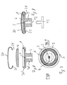
- FIGS. 1-3 now show a first exemplary embodiment of a generally 1 designated transponder shown, which has a housing 2, in which a Antenna element A and one via feed lines Z to antenna element A connected electronic circuit S, in particular a microchip, arranged is.
- the antenna element A and the electronic circuit S of the transponder 1 are known and therefore do not have to be described in more detail.
- the housing 2 of a device for an electromagnetic data exchange performing transponder 1 is button-shaped; the The diameter of the housing 2 is thus much larger than its height.
- a Such a housing shape not only has the advantage that it makes a special compact transponder 1 is made possible. Rather, the button-shaped shape of the housing 2 further has the advantage that a Particularly inconspicuously built transponder 1 is created, which is without technical aids in an advantageous manner from conventional buttons does not distinguish.
- the transponder 1 described is therefore more advantageous Way z. B. can be used in clothing to z. B. theirs Simply control the distribution channel and thus the increasing product piracy to be able to counteract effectively.
- transponder 1 described Another advantage of the transponder 1 described is that it can also be used in an inconspicuous manner for identification purposes can, e.g. B. in that by the button-shaped transponder 1 items of clothing are marked accordingly to them in cleaning facilities and / or to find laundries more easily.
- Another example for the wide range of uses of the transponder 1 described z. B. in that the described transponder 1 as an easy to read Marking mark for animals.
- the housing 2 has a first housing part 3, which in the case shown here as Housing lower part is formed, and an insertable into the first housing part 3 or on this attachable second housing part 4, which in the case shown here is designed as an upper housing part, wherein in the assembled state of these two housing parts a - preferably hermetically sealed - interior 2 'is formed, in which the antenna element A and the electronic Circuit S are included.
- 3a of the first housing part is in a base region 3 shows a shape which is matched to the shape of the antenna element A and is shown here Case circumferential recess 5 'provided a receiving space 5 for forms the antenna element A.
- the bottom area 3a of the first housing part 3 also has a recess 6 ', which has a receiving space 6 for the forms electronic circuit S.
- the inner contour 3b 'of such an outer contour 4' of the second housing part 4 it is agreed that the second housing part 4 can be inserted into the first housing part 3 is and in this inserted state that receiving the antenna element A.
- Well 5 'and the recess receiving the electronic circuit S. 6 'of the bottom 3a of the first housing part 3 covers.
- the amount of circumferential wall area 3b is essentially equal to the thickness of the second housing part 4 in its edge area.
- the diameter of the second housing part 4 is around the thickness of the circumferential Wall 3b is less than that of the first housing part 3 of the housing 2, so that the edge of the second housing part 4 on the inner wall of the circumferential Wall area 3b of the first housing part 3 rests. This will make it easier Encapsulation of the interior 2 'of the housing 1 is achieved.
- a such design is not mandatory. Rather, it is also possible that the second housing part 4 has a larger diameter than the first Housing part 3 and with a wall element corresponding to the wall element 3b is provided so that the first housing part 3 in the through the wall element of the second housing part 4 limited space can be used, that is second housing part 4 can be placed on the first housing part 3, d. H.
- first housing part 3 can be inserted into the second housing part 4.
- second housing part 4 in the first Housing part 3 is inserted.
- the reverse variant, namely that the second Housing part 4 is inserted into the first housing part 3 results for the person skilled in the art simply by having the for the the first housing part 3 provided structural design in the second Provides housing part 4 and vice versa.
- the second housing part 4 has an approximately T-shaped Cross section, so that a lower base region 4a of this housing part 4 in a Receiving opening 14 of the first housing part 3, which is then in the form of a ring in the assembled state of the housing 2 occurs while a transversely to the base area 4a running upper area 4b of the second housing part the recess 5 'and the recess 6' covered.
- first housing part 3 preferably with a substantially flat bottom region 3a, bowl-shaped and consequently the second housing part 4 is platelet-shaped, d. that is, the receiving opening 14 of the first Housing part 3 is omitted.
- the upper housing part 4 has a or - as shown here - several passage openings 9, which are known Way to serve the transponder 1 like a conventional button to attach to a piece of clothing by the transponder 1 using a needle and thread is sewn onto the fabric of the garment.
- FIGS. 4-6 A second exemplary embodiment of a transponder 1 is shown in FIGS. 4-6 shown a housing 2, which in its basic structure essentially corresponds to that of the first embodiment of Figures 1-3, so that identical or corresponding components with the same reference numerals are provided and no longer need to be described.
- the Button-shaped housing 2 of the transponder 1 of the second embodiment has the first housing part 3 with a now essentially flat Floor area 3a, which is delimited by the circumferential wall element 3b becomes.
- the second exemplary embodiment described here thus points to the antenna element A and the electronic circuit S a common recording room 7 and differs from the first exemplary embodiment, which separate receiving spaces, namely the recess 5 'and the recess 6 ', for the antenna element A and the electronic circuit S.
- spacers 11 are preferred here, but is one such construction is not mandatory. Rather, it is the second Embodiment possible, in the bottom area 3a depressions 5 'or Recesses 6 'for receiving the antenna element A and / or the electronic Introduce circuit S.
- the first housing part 3 is of approximately T-shaped design in cross section and has a base area 3a "and a cross-section to the base area 3a" upper region 3b ", the base region 3a" having a bore 12, into which a fastening element 13, shown schematically in FIG. 5, can be introduced is so that the transponder 1 on this fastener 13 an item of clothing can be attached.
- FIGS. 7 to 9 show a third exemplary embodiment of a transponder 1 shown, which is essentially the second embodiment of the figures 4-6 corresponds, so that here again the same parts with the same reference numbers provided and are no longer described in detail.
- the main difference between the second and third embodiment now consists in that in the third embodiment of the transponder 1, a clip 20 is provided which locks the second housing part 4 in the first housing part 3 by the clip 20 with its ends 21 which extend transversely to the base region 3a " grasp the upper region 3b "and thus the second housing part 4 in the or locked in position on the first housing part 3.
- Such a configuration has not only the advantage that the preferably spring clip 20 an easy opening of the housing 2 to replace the electronic circuit S and / or the antenna element A is possible, but that is also preferred cap-shaped bracket 20 an additional protective function trained for the housing 2.
- cap-shaped clip 20 Another advantage of using a cap-shaped clip 20 is that this simply makes the visual appearance of the housing 2 and thus the transponder 1 can be changed because of the the two housing parts 3, 4 existing housing 2 designed differently Brackets 20 can be placed.
- a cap-shaped protective hood is arranged on the housing 2, which is preferably is made of metal.
- FIGS. 10 to 12 show a fourth exemplary embodiment of a transponder 1, the basic structure of which in turn is essentially that of corresponds to the second embodiment of Figures 4 to 6, so here again Identical parts with the same reference numerals and no longer specified to be discribed.
- Such through bore 12 ' has the advantage that this in particular simple way a permanent connection between the transponder 1 and the material carrying the transponder 1 is possible, for. B. in that the transponder 1 by means of a nail passing through the bore 12 ' or a similar connecting element attached to a carrier material becomes.
- connection from the first housing part 3 to the second housing part 4 by gluing, Welding or casting is carried out, but also other types of connection are quite conceivable.
- the second housing part 4 is held in the first housing part 3 only by clamping.
- a potting here, Gluing, welding, etc. of the two housing parts 3, 4 is made.
- the housing 2 it should also be mentioned that it is of course possible to have the housing 2 to manufacture both from flexible, soft and hard plastic, whereby other materials are not excluded. It is also possible that the two housing parts 3, 4 made of different materials are.
- the housing 2 has a circular shape. This is also not mandatory. Rather, it is also possible to use the respective purpose to design the housing 2 also oval or polygonal. Likewise, it is not necessary that the second upper housing part 4 of the first Embodiment has a trough in its surface, or - how in the second embodiment - is slightly dome-shaped. The outer The shape of the second upper housing part 4 can of course also in the wide Limits of a button-like shape can be varied.
Landscapes
- Engineering & Computer Science (AREA)
- Physics & Mathematics (AREA)
- General Physics & Mathematics (AREA)
- Theoretical Computer Science (AREA)
- Computer Hardware Design (AREA)
- Microelectronics & Electronic Packaging (AREA)
- Near-Field Transmission Systems (AREA)
Applications Claiming Priority (6)
| Application Number | Priority Date | Filing Date | Title |
|---|---|---|---|
| DE10109738 | 2001-02-28 | ||
| DE10109738 | 2001-02-28 | ||
| DE10113384 | 2001-03-16 | ||
| DE10113384A DE10113384A1 (de) | 2001-02-28 | 2001-03-16 | Gehäuse für eine Vorrichtung, insbesondere einen Transponder, für einen elektromagnetisch bewirkten Datenaustausch |
| DE20104647U DE20104647U1 (de) | 2001-02-28 | 2001-03-17 | Gehäuse für eine Vorrichtung, insbesondere einen Transponder, für einen elektromagnetisch bewirkten Datenaustausch |
| DE20104647U | 2001-03-17 |
Publications (1)
| Publication Number | Publication Date |
|---|---|
| EP1237288A2 true EP1237288A2 (fr) | 2002-09-04 |
Family
ID=27214319
Family Applications (1)
| Application Number | Title | Priority Date | Filing Date |
|---|---|---|---|
| EP20020004490 Withdrawn EP1237288A2 (fr) | 2001-02-28 | 2002-02-27 | Boitier de transpondeur avec echange de donnes électromagnetique |
Country Status (1)
| Country | Link |
|---|---|
| EP (1) | EP1237288A2 (fr) |
Cited By (4)
| Publication number | Priority date | Publication date | Assignee | Title |
|---|---|---|---|---|
| EP1783668A3 (fr) * | 2005-09-29 | 2007-05-16 | Harting Mitronics AG | Unité de transpondeur |
| EP1764725A4 (fr) * | 2004-07-08 | 2008-10-15 | Ykk Corp | Article avec puce ic sans fil |
| EP1710733A4 (fr) * | 2004-01-29 | 2008-12-17 | Ykk Corp | Article equipe d un moyen d identification, decision di chotomique au sujet d un tel article, et methode de controle de la distribution des marchandises |
| EP2415039A4 (fr) * | 2009-04-03 | 2012-12-26 | Tagsys Sas | Ensemble étiquette rfid et procédé associé |
-
2002
- 2002-02-27 EP EP20020004490 patent/EP1237288A2/fr not_active Withdrawn
Cited By (6)
| Publication number | Priority date | Publication date | Assignee | Title |
|---|---|---|---|---|
| EP1710733A4 (fr) * | 2004-01-29 | 2008-12-17 | Ykk Corp | Article equipe d un moyen d identification, decision di chotomique au sujet d un tel article, et methode de controle de la distribution des marchandises |
| EP2164030A1 (fr) | 2004-01-29 | 2010-03-17 | YKK Corporation | Article equipé d'un moyen d'identification, decision dichotomique au sujet d'un tel article, et methode de controle de la distribution des marchandises |
| EP1764725A4 (fr) * | 2004-07-08 | 2008-10-15 | Ykk Corp | Article avec puce ic sans fil |
| US7652579B2 (en) | 2004-07-08 | 2010-01-26 | Ykk Corporation | Article with wireless IC tag |
| EP1783668A3 (fr) * | 2005-09-29 | 2007-05-16 | Harting Mitronics AG | Unité de transpondeur |
| EP2415039A4 (fr) * | 2009-04-03 | 2012-12-26 | Tagsys Sas | Ensemble étiquette rfid et procédé associé |
Similar Documents
| Publication | Publication Date | Title |
|---|---|---|
| DE102005056428B4 (de) | Magnetverschluß | |
| EP0696891A1 (fr) | Dispositif de fermeture de bracelets | |
| EP1056060B1 (fr) | Elément flexible de sécurité pour marchandises | |
| EP0955515A1 (fr) | Tissu, en particulier tissu résistant aux coups de couteau | |
| EP1237288A2 (fr) | Boitier de transpondeur avec echange de donnes électromagnetique | |
| DE20104647U1 (de) | Gehäuse für eine Vorrichtung, insbesondere einen Transponder, für einen elektromagnetisch bewirkten Datenaustausch | |
| DE202009005948U1 (de) | Vorrichtung zur Aufnahme eines kartenartigen Datenschildes | |
| DE10113384A1 (de) | Gehäuse für eine Vorrichtung, insbesondere einen Transponder, für einen elektromagnetisch bewirkten Datenaustausch | |
| EP0287782B1 (fr) | Elément de fixation | |
| DE29609123U1 (de) | Mütze | |
| EP1338213B1 (fr) | Dispositif pour porter un object circulaire | |
| DE3148986A1 (de) | "einen magnet verwendende verschlusseinrichtung" | |
| DE9111839U1 (de) | Türbeschlag | |
| EP3730325A1 (fr) | Dispositif de protection contre les insectes pour une ouverture d'entrée | |
| DE2259252A1 (de) | Druckknopf | |
| EP0193814A2 (fr) | Objet avec support d'information et procédé de son fabrication | |
| DE9303267U1 (de) | Befestigungssockel für eine Lampe o.dgl. | |
| DE10113919B4 (de) | Gehäuse für einen elektronischen Ausweis | |
| DE20014841U1 (de) | Durch einen Magneten betätigbarer Melder mit zwei Reed-Kontakten | |
| DE3223414A1 (de) | Kennzeichnungsschild, insbesondere fuer lederwaren wie brieftaschen oder dergleichen | |
| DE20022142U1 (de) | Schmuckgegenstand | |
| DE2117190A1 (de) | Druckknopfverschlußelement | |
| DE9410410U1 (de) | Tasche mit Überwurfdeckel | |
| DE2259253A1 (de) | Druckknopf | |
| DE7223716U (de) | Gürtelschnalle, insbesondere für Kleidergürtel |
Legal Events
| Date | Code | Title | Description |
|---|---|---|---|
| PUAI | Public reference made under article 153(3) epc to a published international application that has entered the european phase |
Free format text: ORIGINAL CODE: 0009012 |
|
| AK | Designated contracting states |
Kind code of ref document: A2 Designated state(s): AT BE CH CY DE DK ES FI FR GB GR IE IT LI LU MC NL PT SE TR |
|
| AX | Request for extension of the european patent |
Free format text: AL;LT;LV;MK;RO;SI |
|
| STAA | Information on the status of an ep patent application or granted ep patent |
Free format text: STATUS: THE APPLICATION IS DEEMED TO BE WITHDRAWN |
|
| 18D | Application deemed to be withdrawn |
Effective date: 20040901 |