EP1237273B1 - Méthode pour réduire ou éliminer l'offset d'un signal ac - Google Patents
Méthode pour réduire ou éliminer l'offset d'un signal ac Download PDFInfo
- Publication number
- EP1237273B1 EP1237273B1 EP20010103725 EP01103725A EP1237273B1 EP 1237273 B1 EP1237273 B1 EP 1237273B1 EP 20010103725 EP20010103725 EP 20010103725 EP 01103725 A EP01103725 A EP 01103725A EP 1237273 B1 EP1237273 B1 EP 1237273B1
- Authority
- EP
- European Patent Office
- Prior art keywords
- signal
- offset
- correction
- zero offset
- frequency
- Prior art date
- Legal status (The legal status is an assumption and is not a legal conclusion. Google has not performed a legal analysis and makes no representation as to the accuracy of the status listed.)
- Expired - Lifetime
Links
- 238000000034 method Methods 0.000 title claims description 22
- 230000010354 integration Effects 0.000 claims description 27
- 238000010586 diagram Methods 0.000 description 9
- 238000010438 heat treatment Methods 0.000 description 2
- 238000010276 construction Methods 0.000 description 1
- 238000001914 filtration Methods 0.000 description 1
- 230000000977 initiatory effect Effects 0.000 description 1
- 238000005259 measurement Methods 0.000 description 1
- 230000010363 phase shift Effects 0.000 description 1
- 230000002028 premature Effects 0.000 description 1
Images

Classifications
-
- H—ELECTRICITY
- H02—GENERATION; CONVERSION OR DISTRIBUTION OF ELECTRIC POWER
- H02P—CONTROL OR REGULATION OF ELECTRIC MOTORS, ELECTRIC GENERATORS OR DYNAMO-ELECTRIC CONVERTERS; CONTROLLING TRANSFORMERS, REACTORS OR CHOKE COILS
- H02P6/00—Arrangements for controlling synchronous motors or other dynamo-electric motors using electronic commutation dependent on the rotor position; Electronic commutators therefor
- H02P6/10—Arrangements for controlling torque ripple, e.g. providing reduced torque ripple
Definitions
- the invention relates to a method for reducing or eliminating the Offset of a sensor according to the specified in the preamble of claim 1 Features.
- Modern electric motors are often frequency converter controlled. Of the Frequency converter itself has a closed loop on ensure that the motor is at the frequency and, if necessary Voltage is controlled, which the desired operating point of the Motors corresponds. In such a regulation are usually electrical and / or magnetic quantities of the motor by means of a sensor detected, which are included in the scheme as an actual value. Sensors of this type For example, a Hall sensor, an ammeter in a branch of a Umrichterarmes or a coil for detecting the back EMF signal. Regardless of the type of sensor is on the output regularly Alternating signal, which has a more or less large offset (zero offset) is afflicted.
- This zero offset causes that the control supplied deviating values from the actual values be, which typically leads to torque fluctuations, the even at low offset can be considerable.
- the invention is based on the object, a To provide a method for reducing or eliminating the offset, the avoids these disadvantages.
- the basic idea of the present invention is the alternating signal, ie For example, the signal in the motor or power section of the drive sitting measuring sensor initially over a predetermined time capture, integrate over that time, and then the resulting To divide the area by the time of the coverage period.
- the Integrate the area between a signal formed by the waveform Curve and the zero line determined, namely for the above the zero line lying part as positive and for the sub-zero part as a negative value. Because with a change signal the positive and Negative areas with a suitable choice of the collection period to zero add only the area representing the offset, where the concrete offset value by appropriate time division results.
- the signal is then corresponding to this determined offset corrected, for example, by applying an offset of the amount Her corresponding voltage opposite sign, if that Signal is a voltage signal. Since the signal is an alternating signal, lift during the integration process, those above and below the zero line Surfaces, so that if there is no offset, the value zero is determined. is however, if there is an offset, the calculated value is divided by the integration time the offset by amount and direction.
- the method according to the invention requires that the integration time is chosen, that at least five or more periods of the expected lowest Frequency of the signal can be used to ensure that too one possible one with the lowest frequency signal to be corrected accurate offset correction is done without knowing the period time exactly and the start time of a period for initiating the measurement determine.
- the integration time should not be too large, because this reduces the speed of the process, which in particular then it is important if a signal is to be corrected, that is in the range of the highest expected frequency. If you compare the inventive method with that of the prior art applied method, in which a low pass is used, is so according to the invention on the one hand a much faster to the other but also achieved more accurate offset correction. It is a complete Offsetelemination possible.
- the signal is offset by the offset unlike the low pass did not change, but only through the subsequent offset correction shifted.
- the offset correction is disabled when the signal has a frequency below the expected lowest Frequency is.
- the offset correction with a predetermined Accuracy to be met.
- Such a shutdown of Offset correction in the lower frequency range is particularly acceptable, when the electric motor for driving a centrifugal pump, for example a heating circulation pump is used, as an optionally existing offset in this low-speed area where hardly any power is required from the unit, which plays practically no role.
- centrifugal pump units such low frequencies only become drive through when starting or leaving.
- the lowest Frequency for which the offset correction is to operate it is usually more convenient, the lowest Frequency for which the offset correction is to operate, and the number of periods that pass through the integration time to increase or decrease the integration time, to increase the control speed of the offset correction.
- the integration time can at an integration time that is at least five or more periods of the Signal includes, the integration time practically anywhere on the Waveform can be started without significantly affecting the result. So it is expediently the integration time to the rotational frequency adapted to the electric motor, and in particular to the Speed ranges, for the intended operation of the engine are particularly relevant in terms of offset correction.
- any offset in be removed an alternating signal is preferred however, used to correct a sensor signal, the sensor electrical or magnetic quantities of motor and / or power circuit of the frequency converter and in the regulation of the frequency converter is involved.
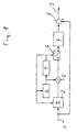
- FIG. 1 shows an apparatus for offset correction according to the inventive method.
- a corrective, offset-biased input signal 1 in the form of an AC signal is supplied to an integrator 2.
- the integrator 2 determines that between a curve formed by the signal and a zero line formed surfaces and sums them over an integration time t. controlled is the integrator 2 via a timer consisting of a timer 3 and a comparator 4, upon reaching the predetermined integration time t both timer 3 and the integrator 2 resets.
- the output of the integrator 2 is like that of the timer 3 with a Connected gate 5, which outputs the outputs of integrator 2 and Timer 3 linked together so that at the output of Gate 5 a the offset of the input signal 1 corresponding Signal is pending.
- a Connected gate 5 which outputs the outputs of integrator 2 and Timer 3 linked together so that at the output of Gate 5 a the offset of the input signal 1 corresponding Signal is pending.
- the output signal of the gate 5 is constant at one Switch 6, which is also controlled by the comparator 4. Of the Switch 6 is closed only when the predetermined integration time t is reached. Then the current output of the logic gate becomes 5, so after the integration time t, a Holding member 7 is supplied, at the output of which a signal is present, that of the during the last integration time t determined offset corresponds. Of the Output of the holding member 8 is connected to a correction member 8, the also the input signal 1 is switched on. Within the correction term 8, the offset coming from the holding member 7, representing the offset Signal subtracted to the input signal 1, whereby the Offset is ideally eliminated. At the output of the correction element 8 is then an offset-corrected output signal 9.
- the integration time t should, as already mentioned in the introduction, be so chosen be that it comprises at least five periods of the input signal 1.
- the integration time t is the smallest Adjust the frequency at which the offset correction should still work. at Drives for pump units, in particular heating circulation pumps
- the offset correction for the operating speeds appropriate frequencies to be interpreted as when starting and Leakage of the engine such a rule is dispensable. Instead this can significantly reduce the correction time and / or the number of Periods that are captured in during the integration time are increased. Especially the latter leads to the fact that the integration time is practical phase independent of the signal can be selected, as well as with the device described with reference to FIG 1
- the integration time is only five or even fewer periods, as known in the art, so it is convenient to synchronize the integration time with the input signal, so that the integration, for example, in the vertex of the The curve formed by the signal begins and ends there again. So the Offseter upset can also at low frequencies or short Integration times are ensured.
- the offset correction is based on a square wave signal State of the art (FIGS. 2a and 2b) and according to the invention (FIG. 2c) shown.
- the input signal 1 consists of a rectangular signal 10, to which an offset 11 of 0.4 has been added
- a low-pass filter 12 with a time constant of 100 seconds is shown intended.
- the output signal shows, is with a low pass 12, although the signal as such (here a square wave signal) practically not changed, the offset correction but only very slowly.
- Period ie after ten periods, this is not yet approximate completed.
- the offset correction such as the accompanying diagram illustrates, although much faster, it is after performed about ten periods, but it has the significant disadvantage that the signal itself is changed.
- the rectangular signal is in the range of its maximum and minimum amplitudes no longer constant, but changed.
- the device-related Construction has been described with reference to Figure 1 and the is illustrated with reference to Figure 2c, the offset correction is already after two Periods completely completed.
- the signal curve corresponds to that of the Input signal 1.
- the method according to the invention is not only considerably faster than the offset correction by means of low pass according to the prior art, but moreover, the signal is not changed despite this fast correction, but only shifted for the purpose of offset correction.
Landscapes
- Engineering & Computer Science (AREA)
- Power Engineering (AREA)
- Control Of Ac Motors In General (AREA)
- Control Of Electric Motors In General (AREA)
Claims (6)
- Procédé pour réduire ou éliminer le décalage du point zéro d'un signal alternatif électrique, en particulier du signal de capteur d'un convertisseur/inverseur électronique d'un moteur électrique, dans lequel le signal est intégré en fonction d'une période de temps et divisé ensuite par cette période de temps, la valeur qui en résulte représentant alors la grandeur du décalage du point zéro à corriger et le signal étant corrigé en conséquence, caractérisé en ce que
une fréquence la plus faible est définie, à laquelle la correction du décalage du point zéro est mise hors service,
et en ce que la durée d'intégration représente au moins cinq périodes ou plus de cette fréquence la plus faible. - Procédé selon la revendication 1, caractérisé en ce que la correction du décalage du point zéro est mise hors service en cas de passage sous une fréquence prédéfinie du signal alternatif.
- Procédé selon l'une des revendications précédentes, caractérisé en ce que la durée d'intégration est adaptée à la fréquence de rotation du moteur électrique, de telle sorte que la durée d'intégration diminue lorsque la fréquence de rotation du moteur croít et inversement.
- Procédé selon l'une des revendications précédentes, caractérisé en ce que le signal émis est, pour la correction du décalage du point zéro, appliqué à un élément de retenue, dont la sortie est connectée par soustraction sur le signal de capteur.
- Procédé selon l'une des revendications précédentes, caractérisé en ce que le signal émis est, pour la correction du décalage du point zéro, appliqué à un élément de retenue, dont la sortie est connectée avec interprétation d'un filtre passe-bas, par soustraction sur le signal de capteur.
- Procédé selon l'une des revendications précédentes, caractérisé en ce qu'il est utilisé pour la correction du décalage du point zéro d'un capteur enregistrant le courant dans un bras d'un onduleur d'un convertisseur de fréquence.
Priority Applications (2)
| Application Number | Priority Date | Filing Date | Title |
|---|---|---|---|
| DE50107825T DE50107825D1 (de) | 2001-02-15 | 2001-02-15 | Verfahren zum Vermindern oder Eliminieren des Offset eines elektrischen Wechselsignals |
| EP20010103725 EP1237273B1 (fr) | 2001-02-15 | 2001-02-15 | Méthode pour réduire ou éliminer l'offset d'un signal ac |
Applications Claiming Priority (1)
| Application Number | Priority Date | Filing Date | Title |
|---|---|---|---|
| EP20010103725 EP1237273B1 (fr) | 2001-02-15 | 2001-02-15 | Méthode pour réduire ou éliminer l'offset d'un signal ac |
Publications (2)
| Publication Number | Publication Date |
|---|---|
| EP1237273A1 EP1237273A1 (fr) | 2002-09-04 |
| EP1237273B1 true EP1237273B1 (fr) | 2005-10-26 |
Family
ID=8176505
Family Applications (1)
| Application Number | Title | Priority Date | Filing Date |
|---|---|---|---|
| EP20010103725 Expired - Lifetime EP1237273B1 (fr) | 2001-02-15 | 2001-02-15 | Méthode pour réduire ou éliminer l'offset d'un signal ac |
Country Status (2)
| Country | Link |
|---|---|
| EP (1) | EP1237273B1 (fr) |
| DE (1) | DE50107825D1 (fr) |
Families Citing this family (2)
| Publication number | Priority date | Publication date | Assignee | Title |
|---|---|---|---|---|
| DE102015225401B4 (de) * | 2015-12-16 | 2025-04-24 | Vitesco Technologies GmbH | Verfahren und Vorrichtung zur Drehwinkeladaption bei einem Drehwinkelsensor eines Gleichstrommotors |
| DE102018119848B4 (de) | 2017-08-29 | 2023-01-05 | Elmos Semiconductor Se | Verfahren zur Ermittlung einer Offsetkorrektur für PMSM Motoren |
Family Cites Families (2)
| Publication number | Priority date | Publication date | Assignee | Title |
|---|---|---|---|---|
| JPH05252785A (ja) * | 1992-03-02 | 1993-09-28 | Omron Corp | モータ制御装置 |
| JP2569248B2 (ja) * | 1992-06-18 | 1997-01-08 | 日本電気計器検定所 | 電子式電力量計 |
-
2001
- 2001-02-15 DE DE50107825T patent/DE50107825D1/de not_active Expired - Lifetime
- 2001-02-15 EP EP20010103725 patent/EP1237273B1/fr not_active Expired - Lifetime
Also Published As
| Publication number | Publication date |
|---|---|
| DE50107825D1 (de) | 2005-12-01 |
| EP1237273A1 (fr) | 2002-09-04 |
Similar Documents
| Publication | Publication Date | Title |
|---|---|---|
| AT405352B (de) | Verfahren zur läuferpositionsbestimmung für einen rotations- oder linear-motor und schaltungsanordnung zur durchführung dieses verfahrens | |
| DE112007001630B4 (de) | Verfahren und Vorrichtung zur Bestimmung der Rotorposition bei einem bürstenlosen und sensorlosen Elektromotor | |
| DE3779752T2 (de) | Motorerregungsschaltung. | |
| DE2648150C2 (de) | Anordnung zur Steuerung der Drehzahl eines über einen Zwischenkreisumrichter gespeisten Asynchronmotors | |
| DE4108466A1 (de) | Steuervorrichtung fuer induktionsmotor | |
| EP1356582B1 (fr) | PROCEDE POUR TRAITER DES DONNEES AVEC UN MOTEUR A COMMUTATION ELECTRONIQUE ET MOTEUR CONçU POUR METTRE EN OEUVRE CE PROCEDE | |
| DE10355651A1 (de) | Verfahren zur Optimierung des Wirkungsgrades eines unter Last betriebenen Motors | |
| EP1657810A1 (fr) | Méthode de l'ajustement automatique de l'angle de commutation des moteurs à courant continu sans balai | |
| DE4235607C2 (de) | Verfahren zur Bestimmung des Ständerflusses einer Asynchronmaschine | |
| EP1879288B1 (fr) | Détermination de l'angle de rotation d'un moteur électrique | |
| DE102013006197B4 (de) | Motorsteuervorrichtung ausgestattet mit Delta-Sigma-Modulations-A/D-Umsetzer | |
| EP1215503A2 (fr) | Mesure du facteur de puissance | |
| WO2011012376A1 (fr) | Procédé et dispositif de détection de pincement à commande temporelle | |
| EP0469177B1 (fr) | Procédé et dispositif pour le redémarrage d'un moteur à induction | |
| EP1237273B1 (fr) | Méthode pour réduire ou éliminer l'offset d'un signal ac | |
| DE69910518T2 (de) | Verfahren zum Wiederstarten eines noch rotierenden permanent-magnetischen Synchronmotors | |
| EP1745336B1 (fr) | Ensemble circuit et procede pour commander et/ou reguler electriquement le mouvement d'une unite commandee electriquement | |
| DE19503658C2 (de) | Verfahren zur Bestimmung einer Größe zum stoßfreien Zuschalten eines drehzahlgeberlos betriebenen Asynchronmotors zu einem Wechselrichter | |
| DE10341511B4 (de) | Verfahren und Schaltungsanordnung für die sensorlose Ermittlung von Lastzuständen von synchronen Linearmotoren | |
| EP3825787B1 (fr) | Procédé de régulation rapide de la valeur moyenne d'une grandeur de régulation, support de données avec programme ainsi que régulation de moteur permettant de mettre en oeuvre ledit procédé et moteur d'entraînement doté d'une telle régulation de moteur | |
| DE4007202C2 (fr) | ||
| DE2554786C3 (de) | Schaltungsanordnung zum Steuern oder Regeln der Drehzahl eines elektrischen Motors | |
| EP0506985B1 (fr) | Procédé de diagnostic d'une immobilisation et dispositif de réalisation de ce procédé | |
| DE102006032192A1 (de) | Drehwinkelbestimmung eines Elektromotors | |
| EP3669241B1 (fr) | Commande d'entraînement à correction d'erreurs autonome des défauts de position |
Legal Events
| Date | Code | Title | Description |
|---|---|---|---|
| PUAI | Public reference made under article 153(3) epc to a published international application that has entered the european phase |
Free format text: ORIGINAL CODE: 0009012 |
|
| AK | Designated contracting states |
Kind code of ref document: A1 Designated state(s): AT BE CH CY DE DK ES FI FR GB GR IE IT LI LU MC NL PT SE TR |
|
| AX | Request for extension of the european patent |
Free format text: AL;LT;LV;MK;RO;SI |
|
| 17P | Request for examination filed |
Effective date: 20021205 |
|
| AKX | Designation fees paid |
Designated state(s): DE FR GB IT |
|
| 17Q | First examination report despatched |
Effective date: 20030508 |
|
| GRAP | Despatch of communication of intention to grant a patent |
Free format text: ORIGINAL CODE: EPIDOSNIGR1 |
|
| GRAS | Grant fee paid |
Free format text: ORIGINAL CODE: EPIDOSNIGR3 |
|
| GRAA | (expected) grant |
Free format text: ORIGINAL CODE: 0009210 |
|
| AK | Designated contracting states |
Kind code of ref document: B1 Designated state(s): DE FR GB IT |
|
| REG | Reference to a national code |
Ref country code: GB Ref legal event code: FG4D Free format text: NOT ENGLISH |
|
| REF | Corresponds to: |
Ref document number: 50107825 Country of ref document: DE Date of ref document: 20051201 Kind code of ref document: P |
|
| GBT | Gb: translation of ep patent filed (gb section 77(6)(a)/1977) |
Effective date: 20060116 |
|
| ET | Fr: translation filed | ||
| PLBE | No opposition filed within time limit |
Free format text: ORIGINAL CODE: 0009261 |
|
| STAA | Information on the status of an ep patent application or granted ep patent |
Free format text: STATUS: NO OPPOSITION FILED WITHIN TIME LIMIT |
|
| 26N | No opposition filed |
Effective date: 20060727 |
|
| PGFP | Annual fee paid to national office [announced via postgrant information from national office to epo] |
Ref country code: IT Payment date: 20150114 Year of fee payment: 15 Ref country code: DE Payment date: 20150327 Year of fee payment: 15 |
|
| PGFP | Annual fee paid to national office [announced via postgrant information from national office to epo] |
Ref country code: FR Payment date: 20141219 Year of fee payment: 15 Ref country code: GB Payment date: 20150211 Year of fee payment: 15 |
|
| REG | Reference to a national code |
Ref country code: DE Ref legal event code: R119 Ref document number: 50107825 Country of ref document: DE |
|
| GBPC | Gb: european patent ceased through non-payment of renewal fee |
Effective date: 20160215 |
|
| REG | Reference to a national code |
Ref country code: FR Ref legal event code: ST Effective date: 20161028 |
|
| PG25 | Lapsed in a contracting state [announced via postgrant information from national office to epo] |
Ref country code: IT Free format text: LAPSE BECAUSE OF NON-PAYMENT OF DUE FEES Effective date: 20160215 |
|
| PG25 | Lapsed in a contracting state [announced via postgrant information from national office to epo] |
Ref country code: FR Free format text: LAPSE BECAUSE OF NON-PAYMENT OF DUE FEES Effective date: 20160229 Ref country code: DE Free format text: LAPSE BECAUSE OF NON-PAYMENT OF DUE FEES Effective date: 20160901 Ref country code: GB Free format text: LAPSE BECAUSE OF NON-PAYMENT OF DUE FEES Effective date: 20160215 |