EP1237273A1 - Méthode pour réduire ou éliminer l'offset d'un signal ac - Google Patents
Méthode pour réduire ou éliminer l'offset d'un signal ac Download PDFInfo
- Publication number
- EP1237273A1 EP1237273A1 EP01103725A EP01103725A EP1237273A1 EP 1237273 A1 EP1237273 A1 EP 1237273A1 EP 01103725 A EP01103725 A EP 01103725A EP 01103725 A EP01103725 A EP 01103725A EP 1237273 A1 EP1237273 A1 EP 1237273A1
- Authority
- EP
- European Patent Office
- Prior art keywords
- signal
- offset
- frequency
- integration time
- time
- Prior art date
- Legal status (The legal status is an assumption and is not a legal conclusion. Google has not performed a legal analysis and makes no representation as to the accuracy of the status listed.)
- Granted
Links
- 238000000034 method Methods 0.000 title claims abstract description 23
- 230000010354 integration Effects 0.000 claims abstract description 29
- 230000000737 periodic effect Effects 0.000 claims abstract 2
- 230000003466 anti-cipated effect Effects 0.000 abstract 1
- 238000010586 diagram Methods 0.000 description 9
- 238000010438 heat treatment Methods 0.000 description 2
- 238000005259 measurement Methods 0.000 description 2
- 238000001514 detection method Methods 0.000 description 1
- 230000008030 elimination Effects 0.000 description 1
- 238000003379 elimination reaction Methods 0.000 description 1
- 238000001914 filtration Methods 0.000 description 1
- 230000010363 phase shift Effects 0.000 description 1
- 230000002028 premature Effects 0.000 description 1
Images

Classifications
-
- H—ELECTRICITY
- H02—GENERATION; CONVERSION OR DISTRIBUTION OF ELECTRIC POWER
- H02P—CONTROL OR REGULATION OF ELECTRIC MOTORS, ELECTRIC GENERATORS OR DYNAMO-ELECTRIC CONVERTERS; CONTROLLING TRANSFORMERS, REACTORS OR CHOKE COILS
- H02P6/00—Arrangements for controlling synchronous motors or other dynamo-electric motors using electronic commutation dependent on the rotor position; Electronic commutators therefor
- H02P6/10—Arrangements for controlling torque ripple, e.g. providing reduced torque ripple
Definitions
- the invention relates to a method for reducing or eliminating the Offset of a sensor according to that specified in the preamble of claim 1 Features.
- Modern electric motors are often frequency converter controlled.
- the Frequency converter itself has a closed control loop ensure that the motor with the frequency and if necessary Voltage is controlled, which the desired operating point of the Motors corresponds.
- electrical and / or magnetic quantities of the motor by means of a sensor recorded, which flow into the control as an actual value.
- sensors can for example a Hall sensor, an ammeter in a branch of a Inverter arm or a coil for recording the back EMF signal. Regardless of the type of sensor, there is a regular output Alternating signal with a more or less large offset (zero point shift) is afflicted.
- This zero point shift leads to that the control is supplied with values that deviate from the actual values which typically leads to torque fluctuations that can be considerable even with a small offset. Furthermore, can by an offset in the control signal for the motor, i.e. in its Power / voltage supply, premature saturation of the magnetic Flow occur, causing the performance of the engine to low values is moved.
- the invention is based on the object To create methods of reducing or eliminating the offset that avoids these disadvantages.
- the basic idea of the present invention is the alternating signal, ie for example the signal of a motor or power section of the frequency converter seated measurement sensor initially over a predetermined time grasp, integrate over that time, and then the resulting Divide the area by the time of the acquisition period.
- the area will be integrated between one formed by the signal curve Curve and the zero line determined, namely for the above the zero line lying part as positive and for the part lying below the zero line as a negative value. Since the positive and negative areas with a suitable choice of the acquisition period to zero add, only the area representing the offset remains, where the concrete offset value is determined by the corresponding time division results.
- the signal is then determined according to this determined offset corrected, for example by applying an offset to the amount corresponding voltage opposite sign if that Signal is a voltage signal.
- the signal is an alternating signal, lift the above and below the zero line during the integration process Surfaces so that if there is no offset, the value zero is determined. is however, if there is an offset, the calculated value is divided by the integration time shows the offset according to amount and direction.
- the method according to the invention requires that the integration time corresponds at least to the time in which the signal three times the Passes through zero point, i.e. a positive and a negative curve having.
- the integration time is expediently chosen so that that at least five or more periods of the lowest expected Frequency of the signal can be used to ensure that too with the lowest frequency signal to be corrected, if possible exact offset correction is carried out without knowing the period exactly and the start of a period to initiate the measurement determine.
- the integration time should not be chosen too long, since this reduces the speed of the process, which in particular is important when a signal needs to be corrected that is in the range of the highest frequency to be expected. If you compare the inventive method with that according to the prior art applied method, in which a low pass is used, so according to the invention on the one hand a much faster on the other but also more accurate offset correction achieved. It is a complete offset elimination possible.
- the signal is determined by the offset unlike the low pass, not changed, but only by the subsequent offset correction shifted.
- the offset correction is expediently deactivated if the signal has a frequency that is below the lowest expected Frequency is. As a result, the offset correction can be carried out with a predetermined one Accuracy are observed.
- Such a shutdown of the Offset correction in the lower frequency range is particularly acceptable if the electric motor for driving a centrifugal pump, for example a heating circulation pump is used, as a possibly existing offset in this low-speed area in which Hardly any power is required from the unit, practically irrelevant.
- Such low frequencies are only used in centrifugal pump units drive through when starting or stopping. These operating states are however, rarely, briefly and for normal operation of the system without Importance.
- any offset in an alternating signal can be removed.
- the method is preferred however, used to correct a sensor signal, the sensor electrical or magnetic quantities of motor and / or power circuit of the frequency converter and recorded in the control of the frequency converter is involved.
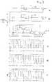
- FIG. 1 shows a device for offset correction by the method according to the invention.
- a to be corrected Input signal 1 with offset in the form of an AC voltage signal is fed to an integrator 2.
- the integrator 2 determines that between a curve formed by the signal and a zero line formed areas and summed them over an integration time ⁇ .
- controlled the integrator 2 is a timer consisting of a timer 3 and a comparator 4 which, when the predetermined integration time is reached ⁇ resets both timer 3 and integrator 2.
- the output of the integrator 2 is the same as that of the timer 3 Logic element 5 connected, which the output signals from integrator 2 and timer 3 linked so that at the output of the Linking element 5 corresponds to the offset of the input signal 1 Signal pending.
- Logic element 5 connected, which the output signals from integrator 2 and timer 3 linked so that at the output of the Linking element 5 corresponds to the offset of the input signal 1 Signal pending.
- Within the link 5 is therefore that in the invention Method provided division of the determined in integrator 2 Area by the integration time specified by timer 3 carried out.
- the output signal of the logic element 5 is constant at one Switch 6 on, which is also controlled by the comparator 4.
- the Switch 6 is only closed when the predetermined integration time ⁇ is reached.
- the current output signal of the logic element 5, i.e. after the integration time ⁇ one Holding member 7 supplied, at the output of which a signal is pending that of offset determined during the last integration time ⁇ .
- the Output of the holding element 8 is connected to a correction element 8, the input signal 1 is also applied. Within the correction link 8 becomes that coming from the holding member 7 and represents the offset Signal switched to the input signal 1 subtracting, which the Ideally, offset is eliminated.
- an offset-corrected output signal 9 is then an offset-corrected output signal 9.
- the integration time ⁇ should, as already mentioned at the beginning, be chosen in this way be that it comprises at least five periods of the input signal 1. If the device for an input signal with a strongly changing frequency should be designed, the integration time ⁇ is the smallest Adjust frequency at which the offset correction should still work. at Drives for pump sets, especially heating circulation pumps it is usually sufficient to use the offset correction for the operating speeds to design appropriate frequencies, because when starting and Leaking the engine is usually unnecessary. Instead can significantly shorten the correction time and / or the number of Periods that are recorded during the integration period are increased. The latter in particular leads to the integration time being practical can be selected independently of the phase of the signal, as is the case with the device described with reference to Figure 1.
- the integration time is only five or even fewer periods, it is advisable to synchronize the integration time with the input signal, so that the integration, for example, at the apex of the curve formed by the signal begins and ends there again. This allows offset detection even at low frequencies or short ones Integration times can be ensured.
- the input signal 1 consists of a square wave signal 10, to which an offset 11 of 0.4 has been added.
- the offset correction is carried out like that associated diagram illustrates, although much faster, it is after about ten periods, but it has the significant disadvantage of that the signal itself is changed.
- the square wave signal is in the range of its maximum and minimum amplitudes no longer constant, but changed.
- the offset correction is already after two Periods completely closed.
- the signal curve corresponds to that of the Input signal 1.
- the method according to the invention is not only considerably faster than the offset correction using a low pass according to the prior art, but furthermore the signal is not changed despite this quick correction, but only moved for the purpose of offset correction.
Landscapes
- Engineering & Computer Science (AREA)
- Power Engineering (AREA)
- Control Of Ac Motors In General (AREA)
- Control Of Electric Motors In General (AREA)
Priority Applications (2)
| Application Number | Priority Date | Filing Date | Title |
|---|---|---|---|
| DE50107825T DE50107825D1 (de) | 2001-02-15 | 2001-02-15 | Verfahren zum Vermindern oder Eliminieren des Offset eines elektrischen Wechselsignals |
| EP20010103725 EP1237273B1 (fr) | 2001-02-15 | 2001-02-15 | Méthode pour réduire ou éliminer l'offset d'un signal ac |
Applications Claiming Priority (1)
| Application Number | Priority Date | Filing Date | Title |
|---|---|---|---|
| EP20010103725 EP1237273B1 (fr) | 2001-02-15 | 2001-02-15 | Méthode pour réduire ou éliminer l'offset d'un signal ac |
Publications (2)
| Publication Number | Publication Date |
|---|---|
| EP1237273A1 true EP1237273A1 (fr) | 2002-09-04 |
| EP1237273B1 EP1237273B1 (fr) | 2005-10-26 |
Family
ID=8176505
Family Applications (1)
| Application Number | Title | Priority Date | Filing Date |
|---|---|---|---|
| EP20010103725 Expired - Lifetime EP1237273B1 (fr) | 2001-02-15 | 2001-02-15 | Méthode pour réduire ou éliminer l'offset d'un signal ac |
Country Status (2)
| Country | Link |
|---|---|
| EP (1) | EP1237273B1 (fr) |
| DE (1) | DE50107825D1 (fr) |
Cited By (2)
| Publication number | Priority date | Publication date | Assignee | Title |
|---|---|---|---|---|
| DE102015225401A1 (de) * | 2015-12-16 | 2017-06-22 | Continental Automotive Gmbh | Verfahren und Vorrichtung zur Drehwinkeladaption bei einem Drehwinkelsensor eines Gleichstrommotors |
| DE102018119848A1 (de) | 2017-08-29 | 2019-02-28 | Elmos Semiconductor Aktiengesellschaft | Verfahren zur Ermittlung einer Offsetkorrektur für PMSM Motoren |
Citations (2)
| Publication number | Priority date | Publication date | Assignee | Title |
|---|---|---|---|---|
| JPH05252785A (ja) * | 1992-03-02 | 1993-09-28 | Omron Corp | モータ制御装置 |
| JPH063384A (ja) * | 1992-06-18 | 1994-01-11 | Nippon Denki Keiki Kenteishiyo | 電子式電力量計 |
-
2001
- 2001-02-15 DE DE50107825T patent/DE50107825D1/de not_active Expired - Lifetime
- 2001-02-15 EP EP20010103725 patent/EP1237273B1/fr not_active Expired - Lifetime
Patent Citations (2)
| Publication number | Priority date | Publication date | Assignee | Title |
|---|---|---|---|---|
| JPH05252785A (ja) * | 1992-03-02 | 1993-09-28 | Omron Corp | モータ制御装置 |
| JPH063384A (ja) * | 1992-06-18 | 1994-01-11 | Nippon Denki Keiki Kenteishiyo | 電子式電力量計 |
Non-Patent Citations (2)
| Title |
|---|
| PATENT ABSTRACTS OF JAPAN vol. 018, no. 017 (E - 1488) 12 January 1994 (1994-01-12) * |
| PATENT ABSTRACTS OF JAPAN vol. 018, no. 194 (P - 1722) 5 April 1994 (1994-04-05) * |
Cited By (4)
| Publication number | Priority date | Publication date | Assignee | Title |
|---|---|---|---|---|
| DE102015225401A1 (de) * | 2015-12-16 | 2017-06-22 | Continental Automotive Gmbh | Verfahren und Vorrichtung zur Drehwinkeladaption bei einem Drehwinkelsensor eines Gleichstrommotors |
| DE102015225401B4 (de) * | 2015-12-16 | 2025-04-24 | Vitesco Technologies GmbH | Verfahren und Vorrichtung zur Drehwinkeladaption bei einem Drehwinkelsensor eines Gleichstrommotors |
| DE102018119848A1 (de) | 2017-08-29 | 2019-02-28 | Elmos Semiconductor Aktiengesellschaft | Verfahren zur Ermittlung einer Offsetkorrektur für PMSM Motoren |
| DE102018119848B4 (de) | 2017-08-29 | 2023-01-05 | Elmos Semiconductor Se | Verfahren zur Ermittlung einer Offsetkorrektur für PMSM Motoren |
Also Published As
| Publication number | Publication date |
|---|---|
| DE50107825D1 (de) | 2005-12-01 |
| EP1237273B1 (fr) | 2005-10-26 |
Similar Documents
| Publication | Publication Date | Title |
|---|---|---|
| EP0884835B1 (fr) | Méthode et dispositif pour contrôler par orientation de son champ un moteur asynchrone sans capteur | |
| DE102005013246B4 (de) | Fehlererfassungssystem für Umrichter | |
| EP0746090A2 (fr) | Procédé de détection de la position de rotor pour un moteur à cylindre rotatif ou un moteur linéaire | |
| DE112006000786T5 (de) | Stromsteuereinheit und Stromversatzkorrekturverfahren für diese | |
| DE3202906A1 (de) | Verfahren und vorrichtung zur steuerung von wechselstrommotoren | |
| DE4108466A1 (de) | Steuervorrichtung fuer induktionsmotor | |
| DE10355651A1 (de) | Verfahren zur Optimierung des Wirkungsgrades eines unter Last betriebenen Motors | |
| DE3811046C2 (de) | Verfahren und Vorrichtung zur Bestimmung des Übersetzungsverhältnisses an einer Druckmaschine | |
| EP1657810A1 (fr) | Méthode de l'ajustement automatique de l'angle de commutation des moteurs à courant continu sans balai | |
| DE102013006197B4 (de) | Motorsteuervorrichtung ausgestattet mit Delta-Sigma-Modulations-A/D-Umsetzer | |
| EP1215503A2 (fr) | Mesure du facteur de puissance | |
| EP0469177B1 (fr) | Procédé et dispositif pour le redémarrage d'un moteur à induction | |
| EP1879288A2 (fr) | Détermination de l'angle de rotation d'un moteur électrique | |
| DE69403625T2 (de) | Verfahren zur Versorgung eines einphasigen Schrittmotors sowie Schaltung hierfür | |
| EP1005147B1 (fr) | Méthode et circuit électrique pour déterminer le gain optimal de l'intégrateur d'un régulateur de vitesse | |
| DE102008002339A1 (de) | Erregungszeitpunkt-Bestimmungsschaltung und Bestimmungsverfahren für einen Erregungszeitpunkt eines Motors | |
| DE19946050A1 (de) | Verfahren zur Drehzahlregelung für geschaltete Reluktanzmotoren (GRM) | |
| EP1237273B1 (fr) | Méthode pour réduire ou éliminer l'offset d'un signal ac | |
| EP1745336B1 (fr) | Ensemble circuit et procede pour commander et/ou reguler electriquement le mouvement d'une unite commandee electriquement | |
| DE3811735C2 (de) | Verfahren zur Frequenzmessung | |
| DE19503658C2 (de) | Verfahren zur Bestimmung einer Größe zum stoßfreien Zuschalten eines drehzahlgeberlos betriebenen Asynchronmotors zu einem Wechselrichter | |
| DE4007202C2 (fr) | ||
| EP0093929B1 (fr) | Procédé pour la commande du flux magnétique d'une machine asynchrone et son appareil | |
| EP0678971B1 (fr) | Méthode pour inverser la direction de rotation pour un moteur CC sans balai à plan régime et moteur CC sans balai | |
| EP0506985B1 (fr) | Procédé de diagnostic d'une immobilisation et dispositif de réalisation de ce procédé |
Legal Events
| Date | Code | Title | Description |
|---|---|---|---|
| PUAI | Public reference made under article 153(3) epc to a published international application that has entered the european phase |
Free format text: ORIGINAL CODE: 0009012 |
|
| AK | Designated contracting states |
Kind code of ref document: A1 Designated state(s): AT BE CH CY DE DK ES FI FR GB GR IE IT LI LU MC NL PT SE TR |
|
| AX | Request for extension of the european patent |
Free format text: AL;LT;LV;MK;RO;SI |
|
| 17P | Request for examination filed |
Effective date: 20021205 |
|
| AKX | Designation fees paid |
Designated state(s): DE FR GB IT |
|
| 17Q | First examination report despatched |
Effective date: 20030508 |
|
| GRAP | Despatch of communication of intention to grant a patent |
Free format text: ORIGINAL CODE: EPIDOSNIGR1 |
|
| GRAS | Grant fee paid |
Free format text: ORIGINAL CODE: EPIDOSNIGR3 |
|
| GRAA | (expected) grant |
Free format text: ORIGINAL CODE: 0009210 |
|
| AK | Designated contracting states |
Kind code of ref document: B1 Designated state(s): DE FR GB IT |
|
| REG | Reference to a national code |
Ref country code: GB Ref legal event code: FG4D Free format text: NOT ENGLISH |
|
| REF | Corresponds to: |
Ref document number: 50107825 Country of ref document: DE Date of ref document: 20051201 Kind code of ref document: P |
|
| GBT | Gb: translation of ep patent filed (gb section 77(6)(a)/1977) |
Effective date: 20060116 |
|
| ET | Fr: translation filed | ||
| PLBE | No opposition filed within time limit |
Free format text: ORIGINAL CODE: 0009261 |
|
| STAA | Information on the status of an ep patent application or granted ep patent |
Free format text: STATUS: NO OPPOSITION FILED WITHIN TIME LIMIT |
|
| 26N | No opposition filed |
Effective date: 20060727 |
|
| PGFP | Annual fee paid to national office [announced via postgrant information from national office to epo] |
Ref country code: IT Payment date: 20150114 Year of fee payment: 15 Ref country code: DE Payment date: 20150327 Year of fee payment: 15 |
|
| PGFP | Annual fee paid to national office [announced via postgrant information from national office to epo] |
Ref country code: FR Payment date: 20141219 Year of fee payment: 15 Ref country code: GB Payment date: 20150211 Year of fee payment: 15 |
|
| REG | Reference to a national code |
Ref country code: DE Ref legal event code: R119 Ref document number: 50107825 Country of ref document: DE |
|
| GBPC | Gb: european patent ceased through non-payment of renewal fee |
Effective date: 20160215 |
|
| REG | Reference to a national code |
Ref country code: FR Ref legal event code: ST Effective date: 20161028 |
|
| PG25 | Lapsed in a contracting state [announced via postgrant information from national office to epo] |
Ref country code: IT Free format text: LAPSE BECAUSE OF NON-PAYMENT OF DUE FEES Effective date: 20160215 |
|
| PG25 | Lapsed in a contracting state [announced via postgrant information from national office to epo] |
Ref country code: FR Free format text: LAPSE BECAUSE OF NON-PAYMENT OF DUE FEES Effective date: 20160229 Ref country code: DE Free format text: LAPSE BECAUSE OF NON-PAYMENT OF DUE FEES Effective date: 20160901 Ref country code: GB Free format text: LAPSE BECAUSE OF NON-PAYMENT OF DUE FEES Effective date: 20160215 |