EP1237273A1 - Method for reducing or eliminating the offset of an ac signal - Google Patents
Method for reducing or eliminating the offset of an ac signal Download PDFInfo
- Publication number
- EP1237273A1 EP1237273A1 EP01103725A EP01103725A EP1237273A1 EP 1237273 A1 EP1237273 A1 EP 1237273A1 EP 01103725 A EP01103725 A EP 01103725A EP 01103725 A EP01103725 A EP 01103725A EP 1237273 A1 EP1237273 A1 EP 1237273A1
- Authority
- EP
- European Patent Office
- Prior art keywords
- signal
- offset
- frequency
- integration time
- time
- Prior art date
- Legal status (The legal status is an assumption and is not a legal conclusion. Google has not performed a legal analysis and makes no representation as to the accuracy of the status listed.)
- Granted
Links
- 238000000034 method Methods 0.000 title claims abstract description 23
- 230000010354 integration Effects 0.000 claims abstract description 29
- 230000000737 periodic effect Effects 0.000 claims abstract 2
- 230000003466 anti-cipated effect Effects 0.000 abstract 1
- 238000010586 diagram Methods 0.000 description 9
- 238000010438 heat treatment Methods 0.000 description 2
- 238000005259 measurement Methods 0.000 description 2
- 238000001514 detection method Methods 0.000 description 1
- 230000008030 elimination Effects 0.000 description 1
- 238000003379 elimination reaction Methods 0.000 description 1
- 238000001914 filtration Methods 0.000 description 1
- 230000010363 phase shift Effects 0.000 description 1
- 230000002028 premature Effects 0.000 description 1
Images

Classifications
-
- H—ELECTRICITY
- H02—GENERATION; CONVERSION OR DISTRIBUTION OF ELECTRIC POWER
- H02P—CONTROL OR REGULATION OF ELECTRIC MOTORS, ELECTRIC GENERATORS OR DYNAMO-ELECTRIC CONVERTERS; CONTROLLING TRANSFORMERS, REACTORS OR CHOKE COILS
- H02P6/00—Arrangements for controlling synchronous motors or other dynamo-electric motors using electronic commutation dependent on the rotor position; Electronic commutators therefor
- H02P6/10—Arrangements for controlling torque ripple, e.g. providing reduced torque ripple
Definitions
- the invention relates to a method for reducing or eliminating the Offset of a sensor according to that specified in the preamble of claim 1 Features.
- Modern electric motors are often frequency converter controlled.
- the Frequency converter itself has a closed control loop ensure that the motor with the frequency and if necessary Voltage is controlled, which the desired operating point of the Motors corresponds.
- electrical and / or magnetic quantities of the motor by means of a sensor recorded, which flow into the control as an actual value.
- sensors can for example a Hall sensor, an ammeter in a branch of a Inverter arm or a coil for recording the back EMF signal. Regardless of the type of sensor, there is a regular output Alternating signal with a more or less large offset (zero point shift) is afflicted.
- This zero point shift leads to that the control is supplied with values that deviate from the actual values which typically leads to torque fluctuations that can be considerable even with a small offset. Furthermore, can by an offset in the control signal for the motor, i.e. in its Power / voltage supply, premature saturation of the magnetic Flow occur, causing the performance of the engine to low values is moved.
- the invention is based on the object To create methods of reducing or eliminating the offset that avoids these disadvantages.
- the basic idea of the present invention is the alternating signal, ie for example the signal of a motor or power section of the frequency converter seated measurement sensor initially over a predetermined time grasp, integrate over that time, and then the resulting Divide the area by the time of the acquisition period.
- the area will be integrated between one formed by the signal curve Curve and the zero line determined, namely for the above the zero line lying part as positive and for the part lying below the zero line as a negative value. Since the positive and negative areas with a suitable choice of the acquisition period to zero add, only the area representing the offset remains, where the concrete offset value is determined by the corresponding time division results.
- the signal is then determined according to this determined offset corrected, for example by applying an offset to the amount corresponding voltage opposite sign if that Signal is a voltage signal.
- the signal is an alternating signal, lift the above and below the zero line during the integration process Surfaces so that if there is no offset, the value zero is determined. is however, if there is an offset, the calculated value is divided by the integration time shows the offset according to amount and direction.
- the method according to the invention requires that the integration time corresponds at least to the time in which the signal three times the Passes through zero point, i.e. a positive and a negative curve having.
- the integration time is expediently chosen so that that at least five or more periods of the lowest expected Frequency of the signal can be used to ensure that too with the lowest frequency signal to be corrected, if possible exact offset correction is carried out without knowing the period exactly and the start of a period to initiate the measurement determine.
- the integration time should not be chosen too long, since this reduces the speed of the process, which in particular is important when a signal needs to be corrected that is in the range of the highest frequency to be expected. If you compare the inventive method with that according to the prior art applied method, in which a low pass is used, so according to the invention on the one hand a much faster on the other but also more accurate offset correction achieved. It is a complete offset elimination possible.
- the signal is determined by the offset unlike the low pass, not changed, but only by the subsequent offset correction shifted.
- the offset correction is expediently deactivated if the signal has a frequency that is below the lowest expected Frequency is. As a result, the offset correction can be carried out with a predetermined one Accuracy are observed.
- Such a shutdown of the Offset correction in the lower frequency range is particularly acceptable if the electric motor for driving a centrifugal pump, for example a heating circulation pump is used, as a possibly existing offset in this low-speed area in which Hardly any power is required from the unit, practically irrelevant.
- Such low frequencies are only used in centrifugal pump units drive through when starting or stopping. These operating states are however, rarely, briefly and for normal operation of the system without Importance.
- any offset in an alternating signal can be removed.
- the method is preferred however, used to correct a sensor signal, the sensor electrical or magnetic quantities of motor and / or power circuit of the frequency converter and recorded in the control of the frequency converter is involved.
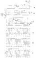
- FIG. 1 shows a device for offset correction by the method according to the invention.
- a to be corrected Input signal 1 with offset in the form of an AC voltage signal is fed to an integrator 2.
- the integrator 2 determines that between a curve formed by the signal and a zero line formed areas and summed them over an integration time ⁇ .
- controlled the integrator 2 is a timer consisting of a timer 3 and a comparator 4 which, when the predetermined integration time is reached ⁇ resets both timer 3 and integrator 2.
- the output of the integrator 2 is the same as that of the timer 3 Logic element 5 connected, which the output signals from integrator 2 and timer 3 linked so that at the output of the Linking element 5 corresponds to the offset of the input signal 1 Signal pending.
- Logic element 5 connected, which the output signals from integrator 2 and timer 3 linked so that at the output of the Linking element 5 corresponds to the offset of the input signal 1 Signal pending.
- Within the link 5 is therefore that in the invention Method provided division of the determined in integrator 2 Area by the integration time specified by timer 3 carried out.
- the output signal of the logic element 5 is constant at one Switch 6 on, which is also controlled by the comparator 4.
- the Switch 6 is only closed when the predetermined integration time ⁇ is reached.
- the current output signal of the logic element 5, i.e. after the integration time ⁇ one Holding member 7 supplied, at the output of which a signal is pending that of offset determined during the last integration time ⁇ .
- the Output of the holding element 8 is connected to a correction element 8, the input signal 1 is also applied. Within the correction link 8 becomes that coming from the holding member 7 and represents the offset Signal switched to the input signal 1 subtracting, which the Ideally, offset is eliminated.
- an offset-corrected output signal 9 is then an offset-corrected output signal 9.
- the integration time ⁇ should, as already mentioned at the beginning, be chosen in this way be that it comprises at least five periods of the input signal 1. If the device for an input signal with a strongly changing frequency should be designed, the integration time ⁇ is the smallest Adjust frequency at which the offset correction should still work. at Drives for pump sets, especially heating circulation pumps it is usually sufficient to use the offset correction for the operating speeds to design appropriate frequencies, because when starting and Leaking the engine is usually unnecessary. Instead can significantly shorten the correction time and / or the number of Periods that are recorded during the integration period are increased. The latter in particular leads to the integration time being practical can be selected independently of the phase of the signal, as is the case with the device described with reference to Figure 1.
- the integration time is only five or even fewer periods, it is advisable to synchronize the integration time with the input signal, so that the integration, for example, at the apex of the curve formed by the signal begins and ends there again. This allows offset detection even at low frequencies or short ones Integration times can be ensured.
- the input signal 1 consists of a square wave signal 10, to which an offset 11 of 0.4 has been added.
- the offset correction is carried out like that associated diagram illustrates, although much faster, it is after about ten periods, but it has the significant disadvantage of that the signal itself is changed.
- the square wave signal is in the range of its maximum and minimum amplitudes no longer constant, but changed.
- the offset correction is already after two Periods completely closed.
- the signal curve corresponds to that of the Input signal 1.
- the method according to the invention is not only considerably faster than the offset correction using a low pass according to the prior art, but furthermore the signal is not changed despite this quick correction, but only moved for the purpose of offset correction.
Landscapes
- Engineering & Computer Science (AREA)
- Power Engineering (AREA)
- Control Of Electric Motors In General (AREA)
- Control Of Ac Motors In General (AREA)
Abstract
Description
Die Erfindung betrifft ein Verfahren zum Vermindern oder Eliminieren des
Offset eines Sensors gemäß den im Oberbegriff des Anspruchs 1 angegebenen
Merkmalen.The invention relates to a method for reducing or eliminating the
Offset of a sensor according to that specified in the preamble of
Moderne Elektromotoren sind häufig frequenzumrichtergesteuert. Der Frequenzumrichter selbst weist einen geschlossenen Regelkreis auf um sicherzustellen, dass der Motor mit der Frequenz und gegebenenfalls Spannung angesteuert wird, welche dem gewünschten Betriebspunkt des Motors entspricht. In einer solchen Regelung werden üblicherweise elektrische und/oder magnetische Größen des Motors mittels eines Sensors erfasst, welche in die Regelung als Ist-Wert einfließen. Sensoren dieser Art können beispielsweise ein Hallsensor, ein Strommesser in einem Zweig eines Umrichterarmes oder eine Spule zur Erfassung des Back-EMF-Signals sein. Unabhängig von der Art des Sensors steht am Ausgang regelmäßig ein Wechselsignal an, das mit einem mehr oder weniger großen Offset (Nullpunktverschiebung) behaftet ist. Diese Nullpunktverschiebung führt dazu, dass der Regelung von den Istwerten abweichende Werte zugeführt werden, was typischerweise zu Drehmomentschwankungen führt, die schon bei geringem Offset beträchtlich sein können. Darüber hinaus kann durch ein Offset im Steuersignal für den Motor, also in seiner Strom/Spannungsversorgung, eine vorzeitige Sättigung des magnetischen Flusses erfolgen, wodurch die Leistung des Motors zu geringen Werten hinverschoben wird.Modern electric motors are often frequency converter controlled. The Frequency converter itself has a closed control loop ensure that the motor with the frequency and if necessary Voltage is controlled, which the desired operating point of the Motors corresponds. In such a scheme usually electrical and / or magnetic quantities of the motor by means of a sensor recorded, which flow into the control as an actual value. Such sensors can for example a Hall sensor, an ammeter in a branch of a Inverter arm or a coil for recording the back EMF signal. Regardless of the type of sensor, there is a regular output Alternating signal with a more or less large offset (zero point shift) is afflicted. This zero point shift leads to that the control is supplied with values that deviate from the actual values which typically leads to torque fluctuations that can be considerable even with a small offset. Furthermore, can by an offset in the control signal for the motor, i.e. in its Power / voltage supply, premature saturation of the magnetic Flow occur, causing the performance of the engine to low values is moved.
Zur Verminderung dieses Offset im elektrischen Wechselsignal ist es bekannt, einen Tiefpass einzusetzen. Eine solche Vorrichtung ist beispielsweise aus DE 196 48 696 Al bekannt. Nachteilig bei dem Einsatz eines solchen Tiefpasses ist es, dass zum einen das Offset nie vollständig entfernt wird und zum anderen je nach gewählter Zeitkonstante des Filters entweder eine sehr langsame Korrektur oder aber eine vergleichsweise große Signalveränderung erfolgt. Auch kann es Probleme durch eine Phasenverschiebung geben.To reduce this offset in the alternating electrical signal, it is known use a low pass. Such a device is for example known from DE 196 48 696 Al. A disadvantage when using such a device It is a low pass that, on the one hand, the offset is never completely removed and on the other hand either one depending on the selected time constant of the filter very slow correction or a comparatively large signal change he follows. There may also be problems due to a phase shift give.
Vor diesem Hintergrund liegt der Erfindung die Aufgabe zu Grunde, ein Verfahren zum Vermindern oder Eliminieren des Offset zu schaffen, das diese Nachteile vermeidet.Against this background, the invention is based on the object To create methods of reducing or eliminating the offset that avoids these disadvantages.
Diese Aufgabe wird gemäß der Erfindung durch die in Anspruch 1 angegebenen
Merkmale gelöst. Vorteilhafte Ausgestaltung der Erfindung sind
in den Unteransprüchen, der nachfolgenden Beschreibung sowie der
Zeichnung angegeben.This object is achieved according to the invention by those specified in
Grundgedanke der vorliegenden Erfindung ist es, das Wechselsignal, also beispielsweise das Signal eines im Motor oder Leistungsteil des Frequenzumrichters sitzenden Messensors zunächst über eine vorbestimmte Zeit zu erfassen, über diese Zeit zu integrieren, und die sich dann ergebende Fläche durch die Zeit des Erfassungszeitraumes zu dividieren. Durch das Integrieren wird die Fläche zwischen einer durch den Signalverlauf gebildeten Kurve und der Nulllinie ermittelt, und zwar für den über der Nulllinie liegenden Teil als positiver und für den unter der Nulllinie liegenden Teil als negativer Wert. Da sich bei einem Wechselsignal die positiven und negativen Flächen bei geeigneter Wahl des Erfassungszeitraums zu Null addieren, verbleibt lediglich die das Offset repräsentierende Fläche, wobei sich der konkrete Offsetwert durch entsprechende Zeitdivision ergibt. Das Signal wird dann entsprechend diesem ermittelten Offset korrigiert, beispielsweise durch Aufschalten einer dem Offset vom Betrag her entsprechenden Spannung umgekehrten Vorzeichens, wenn das Signal ein Spannungssignal ist. Da das Signal ein Wechselsignal ist, heben sich beim Integrationsvorgang die über und unter der Nulllinie liegenden Flächen auf, so dass bei fehlendem Offset der Wert Null ermittelt wird. Ist jedoch ein Offset vorhanden, so ergibt der ermittelte Wert dividiert durch die Integrationszeit das Offset nach Betrag und Richtung an. The basic idea of the present invention is the alternating signal, ie for example the signal of a motor or power section of the frequency converter seated measurement sensor initially over a predetermined time grasp, integrate over that time, and then the resulting Divide the area by the time of the acquisition period. By the The area will be integrated between one formed by the signal curve Curve and the zero line determined, namely for the above the zero line lying part as positive and for the part lying below the zero line as a negative value. Since the positive and negative areas with a suitable choice of the acquisition period to zero add, only the area representing the offset remains, where the concrete offset value is determined by the corresponding time division results. The signal is then determined according to this determined offset corrected, for example by applying an offset to the amount corresponding voltage opposite sign if that Signal is a voltage signal. Since the signal is an alternating signal, lift the above and below the zero line during the integration process Surfaces so that if there is no offset, the value zero is determined. is however, if there is an offset, the calculated value is divided by the integration time shows the offset according to amount and direction.
Das erfindungsgemäße Verfahren setzt allerdings voraus, das die Integrationszeit mindestens der Zeit entspricht, in der das Signal dreimal den Nullpunkt durchläuft, d.h. einen positiven und einen negativen Kurvenverlauf aufweist. Zweckmäßigerweise wird die Integrationszeit so gewählt, dass mindestens fünf oder mehr Perioden der zu erwartenden niedrigsten Frequenz des Signals herangezogen werden, um sicherzustellen, dass auch bei dem niedrigstfrequentesten zu korrigierenden Signal eine möglichst genaue Offsetkorrektur erfolgt ohne die Periodenzeit genau zu kennen und den Anfangszeitpunkt einer Periode zur Einleitung der Messung zu ermitteln.However, the method according to the invention requires that the integration time corresponds at least to the time in which the signal three times the Passes through zero point, i.e. a positive and a negative curve having. The integration time is expediently chosen so that that at least five or more periods of the lowest expected Frequency of the signal can be used to ensure that too with the lowest frequency signal to be corrected, if possible exact offset correction is carried out without knowing the period exactly and the start of a period to initiate the measurement determine.
Andererseits sollte die Integrationszeit auch nicht zu groß gewählt werden, da hierdurch die Schnelligkeit des Verfahrens vermindert wird, was insbesondere dann von Bedeutung ist, wenn ein Signal zu korrigieren ist, das im Bereich der höchsten zu erwartenden Frequenz liegt. Vergleicht man das erfindungsgemäße Verfahren mit dem nach dem Stand der Technik angewandten Verfahren, bei dem ein Tiefpass eingesetzt wird, so wird gemäß der Erfindung zum einen eine wesentlich schnellere zum anderen aber auch genauere Offsetkorrektur erreicht. Es ist eine vollständige Offsetelemination möglich. Darüber hinaus wird das Signal durch die Offsetermittelung anders als beim Tiefpass nicht verändert, sondern erst durch die nachfolgende Offsetkorrektur verschoben.On the other hand, the integration time should not be chosen too long, since this reduces the speed of the process, which in particular is important when a signal needs to be corrected that is in the range of the highest frequency to be expected. If you compare the inventive method with that according to the prior art applied method, in which a low pass is used, so according to the invention on the one hand a much faster on the other but also more accurate offset correction achieved. It is a complete offset elimination possible. In addition, the signal is determined by the offset unlike the low pass, not changed, but only by the subsequent offset correction shifted.
Zweckmäßigerweise wird die Offsetkorrektur außer Betrieb gesetzt, wenn das Signal eine Frequenz aufweist, die unter der zu erwartenden niedrigsten Frequenz liegt. Hierdurch kann die Offsetkorrektur mit einer vorbestimmten Genauigkeit eingehalten werden. Ein solches Abschalten der Offsetkorrektur im unteren Frequenzbereich ist insbesondere dann hinnehmbar, wenn der Elektromotor zum Antrieb einer Kreiselpumpe, beispielsweise einer Heizungsumwälzpumpe eingesetzt wird, da ein gegebenenfalls vorhandenes Offset in diesem niedertourigen Bereich, in dem vom Aggregat kaum Leistung gefordert wird, praktisch keine Rolle spielt. Bei Kreiselpumpenaggregaten werden solche niedrigen Frequenzen nur beim Anfahren oder Auslaufen durchfahren. Diese Betriebszustände sind allerdings selten, kurzzeitig und für den Regelbetrieb der Anlage ohne Bedeutung. Bei diesem Einsatz ist es meist zweckmäßiger, die niedrigste Frequenz, für welche die Offsetkorrektur arbeiten soll, anzuheben, und dafür die Anzahl der Perioden, die innerhalb der Integrationszeit durchlaufen werden, zu vergrößern oder aber die Integrationszeit zu verkleinern, um die Regelgeschwindigkeit der Offsetkorrektur zu erhöhen. Auch kann bei einer Integrationszeit, die mindestens fünf oder mehr Perioden des Signals umfasst, die Integrationszeit praktisch an beliebiger Stelle des Signalverlaufs begonnen werden, ohne das Ergebnis merklich zu beeinflussen. Es wird also zweckmäßigerweise die Integrationszeit an die Drehfrequenz des Elektromotors angepasst, und zwar insbesondere an die Drehzahlbereiche, die für den bestimmungsgemäßen Betrieb des Motors im Hinblick auf die Offsetkorrektur besonders relevant sind.The offset correction is expediently deactivated if the signal has a frequency that is below the lowest expected Frequency is. As a result, the offset correction can be carried out with a predetermined one Accuracy are observed. Such a shutdown of the Offset correction in the lower frequency range is particularly acceptable if the electric motor for driving a centrifugal pump, for example a heating circulation pump is used, as a possibly existing offset in this low-speed area in which Hardly any power is required from the unit, practically irrelevant. Such low frequencies are only used in centrifugal pump units drive through when starting or stopping. These operating states are however, rarely, briefly and for normal operation of the system without Importance. In this application, it is usually more appropriate to use the lowest Increase the frequency for which the offset correction is to work, and but the number of periods that go through within the integration time increase or decrease the integration time, to increase the control speed of the offset correction. Can too with an integration time that is at least five or more periods of Signal includes, the integration time practically anywhere in the Signal course can be started without noticeably influencing the result. The integration time to the rotational frequency is therefore expedient adapted to the electric motor, in particular to the Speed ranges required for the intended operation of the engine are particularly relevant with regard to the offset correction.
Anders als bei der Tiefpassfilterung muss bei dem erfindungsgemäßen Verfahren nach dem Integrieren und Dividieren ein Halteglied vorgesehen sein, das den nach dem Intervall ermittelten Offsetwert bis zur Ermittlung des nächsten Offsetwertes hält und das Signal entsprechend korrigiert. Um unkontrollierte Schwingungen des Systems zu vermeiden, kann es zweckmäßig sein, dem Halteglied einen Tiefpass nachzuschalten, bevor das Offsetsignal dem Signal subtrahierend aufgeschaltet wird.In contrast to low-pass filtering, in the case of the invention Method provided after integrating and dividing a holding member be the offset value determined according to the interval until the determination of the next offset value holds and the signal is corrected accordingly. Around To avoid uncontrolled vibrations of the system, it can be useful be a low pass after the holding link before that Offset signal is applied subtracting the signal.
Mit dem erfindungsgemäßen Verfahren kann grundsätzlich jedes Offset in einem Wechselsignal entfernt werden. Bevorzugt wird das Verfahren jedoch eingesetzt, um ein Sensorsignal zu korrigieren, wobei der Sensor elektrische oder magnetische Größen von Motor und/oder Leistungskreis des Frequenzumrichters erfasst und in die Regelung des Frequenzumrichters eingebunden ist.In principle, any offset in an alternating signal can be removed. The method is preferred however, used to correct a sensor signal, the sensor electrical or magnetic quantities of motor and / or power circuit of the frequency converter and recorded in the control of the frequency converter is involved.
Die Erfindung ist nachfolgend anhand eines in der Zeichnung dargestellten Ausführungsbeispieles im Einzelnen erläutert. Es zeigen
Figur 1- ein Prinzipschaltbild einer Vorrichtung zum Ausführen des erfindungsgemäßen Verfahrens,
- Figur 2a
- ein Prinzipschaltbild einer Vorrichtung nach dem Stand der Technik und ein zugehöriger Signalverlauf,
- Figur 2b
- ein Prinzipschaltbild einer weiteren Vorrichtung nach dem Stand der Technik und ein Signalverlauf und
- Figur 2c
- ein Prinzipschaltbild gemäß
Figur 1 und der dazugehörige Signalverlauf
- Figure 1
- 2 shows a basic circuit diagram of a device for executing the method according to the invention,
- Figure 2a
- 1 shows a basic circuit diagram of a device according to the prior art and an associated signal curve,
- Figure 2b
- a schematic diagram of another device according to the prior art and a waveform and
- Figure 2c
- a schematic diagram of Figure 1 and the associated waveform
Das in Figur 1 dargestellte Blockschaltbild zeigt eine Vorrichtung zur Offsetkorrektur
nach dem erfindungsgemäßen Verfahren. Ein zu korrigierendes,
mit Offset behaftetes Eingangssignal 1 in Form eines Wechselspannungssignals
wird einem Integrator 2 zugeführt. Der Intergrator 2 ermittelt
die zwischen einer durch das Signal gebildeten Kurve und einer Nulllinie
gebildeten Flächen und summiert diese über eine Integrationszeit †. Gesteuert
wird der Integrator 2 über ein Zeitglied bestehend aus einem Timer
3 und einem Komparator 4, der beim Erreichen der vorbestimmten Integrationszeit
† sowohl den Timer 3 als auch den Integrator 2 zurücksetzt.The block diagram shown in FIG. 1 shows a device for offset correction
by the method according to the invention. A to be corrected
Der Ausgang des Integrators 2 ist ebenso wie der des Timers 3 mit einem
Verknüpfungsglied 5 verbunden, welches die Ausgangssignale von Integrator
2 und Timer 3 so miteinander verknüpft, dass am Ausgang des
Verknüpfungsglied 5 ein dem Offset des Eingangssignals 1 entsprechendes
Signal ansteht. Innerhalb des Verknüpfungsglied 5 wird also die im erfindungsgemäßen
Verfahren vorgesehene Division der im Integrator 2 ermittelten
Fläche durch die vom Timer 3 vorgegebene Integrationszeit
durchgeführt.The output of the
Das Ausgangssignal des Verknüpfungsglieds 5 steht konstant an einem
Schalter 6 an, der ebenfalls durch den Komparator 4 gesteuert ist. Der
Schalter 6 wird erst dann geschlossen, wenn die vorbestimmte Integrationszeit
† erreicht ist. Dann wird das aktuelle Ausgangssignal des Verknüpfungsglieds
5, also das nach Ablauf der Integrationszeit †, einem
Halteglied 7 zugeführt, an dessen Ausgang ein Signal ansteht, das dem des
während der letzten Integrationszeit † ermittelten Offset entspricht. Der
Ausgang des Halteglieds 8 ist mit einem Korrekturglied 8 verbunden, dem
auch das Eingangssignal 1 aufgeschaltet ist. Innerhalb des Korrekturglieds
8 wird das vom Halteglied 7 kommende, das Offset repräsentierende
Signal auf das Eingangssignal 1 subtrahierend geschaltet, wodurch das
Offset im Idealfall eliminiert wird. Am Ausgang des Korrekturglieds 8 steht
dann ein offsetkorrigiertes Ausgangssignal 9 an.The output signal of the
Die Integrationszeit † sollte, wie Eingangs bereits erwähnt ist, so gewählt
sein, dass sie mindestens fünf Perioden des Eingangssignals 1 umfasst.
Wenn die Vorrichtung für ein Eingangssignal mit stark wechselnder Frequenz
ausgelegt werden soll, so ist die Integrationszeit † auf die kleinste
Frequenz abzustimmen, bei der die Offsetkorrektur noch arbeiten soll. Bei
Antrieben für Pumpenaggregate, insbesondere Heizungsumwälzpumpen
reicht es in der Regel aus, die Offsetkorrektur für die den Betriebsdrehzahlen
entsprechenden Frequenzen auszulegen, da beim Anfahren und
Auslaufen des Motors eine solche in der Regel entbehrlich ist. Stattdessen
kann hierfür die Korrekturzeit deutlich verkürzt und/oder die Anzahl der
Perioden, die in während der Integrationszeit erfasst werden, erhöht werden.
Insbesondere letzteres führt dazu, dass die Integrationszeit praktisch
phasenunabhängig vom Signal gewählt werden kann, so wie es auch bei
der anhand von Figur 1 beschriebenen Vorrichtung erfolgt.The integration time † should, as already mentioned at the beginning, be chosen in this way
be that it comprises at least five periods of the
Beträgt die Integrationszeit jedoch nur fünf oder noch weniger Perioden, so ist es zweckmäßig, die Intergrationszeit mit dem Eingangssignal zu synchronisieren, so dass die Intergration beispielsweise im Scheitelpunkt der durch das Signal gebildeten Kurve beginnt und auch dort wieder endet. So kann die Offseterfassung auch bei niedrigen Frequenzen bzw. kurzen Intergrationszeiten sichergestellt werden.However, if the integration time is only five or even fewer periods, it is advisable to synchronize the integration time with the input signal, so that the integration, for example, at the apex of the curve formed by the signal begins and ends there again. This allows offset detection even at low frequencies or short ones Integration times can be ensured.
In Figur 2 ist anhand eines Rechtecksignals die Offsetkorrektur nach dem
Stand der Technik (Figur 2a und 2b) sowie gemäß der Erfindung (Figur 2c)
dargestellt. Das Eingangssignal 1 besteht aus einem Rechtecksignal 10,
dem ein Offset 11 von 0,4 hinzugefügt worden ist. In Figure 2, the offset correction after the
State of the art (Figures 2a and 2b) and according to the invention (Figure 2c)
shown. The
Gemäß Figur 2a ist ein Tiefpass 12 mit einer Zeitkonstante von 100 Sekunden
vorgesehen. Wie sich aus dem zugehörigen Kurvenverlauf, der das Ausgangssignal
zeigt, ergibt, wird mit einem Tiefpass 12 zwar das Signal als
solches (hier ein Rechtecksignal) praktisch nicht verändert, die Offsetkorrektur
erfolgt jedoch nur sehr langsam. Am Ende des im Diagram dargestellten
Zeitraums, also nach zehn Perioden ist diese noch nicht annähernd
abgeschlossen.According to FIG. 2a, there is a
Bei dem anhand von Figur 2b dargestellten Tiefpass 13 der einer Zeitkonstante
von fünf Sekunden aufweist, erfolgt die Offsetkorrektur, wie das
zugehörige Diagram verdeutlicht, zwar wesentlich schneller, es ist nach
etwa zehn Perioden durchgeführt, es hat jedoch den erheblichen Nachteil,
dass das Signal selbst verändert wird. Wie aus dem Diagram gemäß
Figur 2b sichtbar ist, ist das Rechtecksignal im Bereich seiner maximalen
und minimalen Amplituden nicht mehr konstant, sondern verändert.In the case of the low-
Mit dem erfindungsgemäßen Verfahren hingegen, dessen vorrichtungsmäßiger
Aufbau anhand von Figur 1 beschrieben worden ist und das
anhand von Figur 2c dargestellt ist, ist die Offsetkorrektur bereits nach zwei
Perioden vollständig abgeschlossen. Der Signalverlauf entspricht dem des
Eingangssignals 1. Wie die Diagrame gemäß Figur 2a, b und c verdeutlichen,
ist das erfindungsgemäße Verfahren nicht nur erheblich schneller als
die Offsetkorrektur mittels Tiefpass nach dem Stand der Technik, sondern
darüber hinaus wird das Signal trotz dieser schnellen Korrektur nicht verändert,
sondern nur zum Zweck der Offsetkorrektur verschoben. In contrast, with the method according to the invention, its device-like
Structure has been described with reference to Figure 1 and that
2c, the offset correction is already after two
Periods completely closed. The signal curve corresponds to that of the
- 1 -1 -
- Eingangssignalinput
- 2 -2 -
- Integratorintegrator
- 3 -3 -
- Timertimer
- 4 -4 -
- Komparatorcomparator
- 5 -5 -
- Verknüpfungsgliedcombiner
- 6 -6 -
- Schalterswitch
- 7 -7 -
- Haltegliedretaining member
- 8 -8th -
- Korrekturgliedcorrection term
- 9 -9 -
- Ausgangssignaloutput
- 10 -10 -
- Rechtecksignalsquare wave
- 11 -11 -
- Offsetoffset
- 12 -12 -
- Tiefpasslowpass
- 13 -13 -
- Tiefpasslowpass
- † -† -
- IntegrationszeitraumIntegration period
Claims (7)
Priority Applications (2)
| Application Number | Priority Date | Filing Date | Title |
|---|---|---|---|
| DE50107825T DE50107825D1 (en) | 2001-02-15 | 2001-02-15 | A method for reducing or eliminating the offset of an electrical alternating signal |
| EP20010103725 EP1237273B1 (en) | 2001-02-15 | 2001-02-15 | Method for reducing or eliminating the offset of an ac signal |
Applications Claiming Priority (1)
| Application Number | Priority Date | Filing Date | Title |
|---|---|---|---|
| EP20010103725 EP1237273B1 (en) | 2001-02-15 | 2001-02-15 | Method for reducing or eliminating the offset of an ac signal |
Publications (2)
| Publication Number | Publication Date |
|---|---|
| EP1237273A1 true EP1237273A1 (en) | 2002-09-04 |
| EP1237273B1 EP1237273B1 (en) | 2005-10-26 |
Family
ID=8176505
Family Applications (1)
| Application Number | Title | Priority Date | Filing Date |
|---|---|---|---|
| EP20010103725 Expired - Lifetime EP1237273B1 (en) | 2001-02-15 | 2001-02-15 | Method for reducing or eliminating the offset of an ac signal |
Country Status (2)
| Country | Link |
|---|---|
| EP (1) | EP1237273B1 (en) |
| DE (1) | DE50107825D1 (en) |
Cited By (2)
| Publication number | Priority date | Publication date | Assignee | Title |
|---|---|---|---|---|
| DE102015225401A1 (en) * | 2015-12-16 | 2017-06-22 | Continental Automotive Gmbh | Method and device for the rotation angle adaptation in a rotation angle sensor of a DC motor |
| DE102018119848A1 (en) | 2017-08-29 | 2019-02-28 | Elmos Semiconductor Aktiengesellschaft | Method for determining offset correction for PMSM motors |
Citations (2)
| Publication number | Priority date | Publication date | Assignee | Title |
|---|---|---|---|---|
| JPH05252785A (en) * | 1992-03-02 | 1993-09-28 | Omron Corp | Motor controller |
| JPH063384A (en) * | 1992-06-18 | 1994-01-11 | Nippon Denki Keiki Kenteishiyo | Electronic watthour meter |
-
2001
- 2001-02-15 DE DE50107825T patent/DE50107825D1/en not_active Expired - Lifetime
- 2001-02-15 EP EP20010103725 patent/EP1237273B1/en not_active Expired - Lifetime
Patent Citations (2)
| Publication number | Priority date | Publication date | Assignee | Title |
|---|---|---|---|---|
| JPH05252785A (en) * | 1992-03-02 | 1993-09-28 | Omron Corp | Motor controller |
| JPH063384A (en) * | 1992-06-18 | 1994-01-11 | Nippon Denki Keiki Kenteishiyo | Electronic watthour meter |
Non-Patent Citations (2)
| Title |
|---|
| PATENT ABSTRACTS OF JAPAN vol. 018, no. 017 (E - 1488) 12 January 1994 (1994-01-12) * |
| PATENT ABSTRACTS OF JAPAN vol. 018, no. 194 (P - 1722) 5 April 1994 (1994-04-05) * |
Cited By (4)
| Publication number | Priority date | Publication date | Assignee | Title |
|---|---|---|---|---|
| DE102015225401A1 (en) * | 2015-12-16 | 2017-06-22 | Continental Automotive Gmbh | Method and device for the rotation angle adaptation in a rotation angle sensor of a DC motor |
| DE102015225401B4 (en) * | 2015-12-16 | 2025-04-24 | Vitesco Technologies GmbH | Method and device for angle adaptation in a rotation angle sensor of a DC motor |
| DE102018119848A1 (en) | 2017-08-29 | 2019-02-28 | Elmos Semiconductor Aktiengesellschaft | Method for determining offset correction for PMSM motors |
| DE102018119848B4 (en) | 2017-08-29 | 2023-01-05 | Elmos Semiconductor Se | Procedure for determining an offset correction for PMSM motors |
Also Published As
| Publication number | Publication date |
|---|---|
| EP1237273B1 (en) | 2005-10-26 |
| DE50107825D1 (en) | 2005-12-01 |
Similar Documents
| Publication | Publication Date | Title |
|---|---|---|
| DE68909232T2 (en) | STARTING A BRUSHLESS DC MOTOR. | |
| DE102005013246B4 (en) | Error detection system for converters | |
| EP0746090A2 (en) | Method for rotor position detection for a revolving cylinder motor or a linear motor | |
| DE112006000786T5 (en) | Current control unit and current offset correction method for this | |
| DE3202906A1 (en) | METHOD AND DEVICE FOR CONTROLLING AC MOTORS | |
| DE19724946A1 (en) | Method and device for speed control of an encoderless, field-oriented asynchronous machine | |
| DE4108466A1 (en) | CONTROL DEVICE FOR INDUCTION MOTOR | |
| DE3811046C2 (en) | Method and device for determining the gear ratio on a printing press | |
| EP1657810A1 (en) | Method for the automatic adjustment of the commutation angle of brushless DC motors | |
| DE102013006197B4 (en) | Motor control device equipped with delta-sigma modulation A / D converter | |
| EP1215503A2 (en) | Measuring power factor | |
| EP0469177B1 (en) | Method and device for restarting an induction motor | |
| EP1879288A2 (en) | Rotation angle determination for an electric motor | |
| DE69403625T2 (en) | Process for supplying a single-phase stepper motor and circuit therefor | |
| EP1005147B1 (en) | Method and electronic circuit for determination of the optimal integrator gain for a speed controller | |
| DE102008002339A1 (en) | Excitation timing determination circuit and determination method for an energization timing of an engine | |
| DE19946050A1 (en) | Revolution rate regulation for switched reluctance motors involves PWM operation and switching static converter transistor during set period if motor in or close to stable state | |
| EP1237273B1 (en) | Method for reducing or eliminating the offset of an ac signal | |
| DE69029711T2 (en) | Circuit arrangement for controlling a free-piston engine, in particular a refrigerator compressor | |
| EP1745336B1 (en) | Circuit arrangement and method for electrically controlling and/or regulating the movement of an electrically driven unit | |
| DE4107362C2 (en) | Process for the bumpless connection of a converter to a three-phase asynchronous machine rotating at an unknown speed | |
| DE3811735C2 (en) | Frequency measurement method | |
| DE19503658C2 (en) | Method for determining a variable for the bumpless connection of an asynchronous motor operated without a speed sensor to an inverter | |
| DE4007202C2 (en) | ||
| EP1879289B1 (en) | Determination of the angle of rotation of an electric motor |
Legal Events
| Date | Code | Title | Description |
|---|---|---|---|
| PUAI | Public reference made under article 153(3) epc to a published international application that has entered the european phase |
Free format text: ORIGINAL CODE: 0009012 |
|
| AK | Designated contracting states |
Kind code of ref document: A1 Designated state(s): AT BE CH CY DE DK ES FI FR GB GR IE IT LI LU MC NL PT SE TR |
|
| AX | Request for extension of the european patent |
Free format text: AL;LT;LV;MK;RO;SI |
|
| 17P | Request for examination filed |
Effective date: 20021205 |
|
| AKX | Designation fees paid |
Designated state(s): DE FR GB IT |
|
| 17Q | First examination report despatched |
Effective date: 20030508 |
|
| GRAP | Despatch of communication of intention to grant a patent |
Free format text: ORIGINAL CODE: EPIDOSNIGR1 |
|
| GRAS | Grant fee paid |
Free format text: ORIGINAL CODE: EPIDOSNIGR3 |
|
| GRAA | (expected) grant |
Free format text: ORIGINAL CODE: 0009210 |
|
| AK | Designated contracting states |
Kind code of ref document: B1 Designated state(s): DE FR GB IT |
|
| REG | Reference to a national code |
Ref country code: GB Ref legal event code: FG4D Free format text: NOT ENGLISH |
|
| REF | Corresponds to: |
Ref document number: 50107825 Country of ref document: DE Date of ref document: 20051201 Kind code of ref document: P |
|
| GBT | Gb: translation of ep patent filed (gb section 77(6)(a)/1977) |
Effective date: 20060116 |
|
| ET | Fr: translation filed | ||
| PLBE | No opposition filed within time limit |
Free format text: ORIGINAL CODE: 0009261 |
|
| STAA | Information on the status of an ep patent application or granted ep patent |
Free format text: STATUS: NO OPPOSITION FILED WITHIN TIME LIMIT |
|
| 26N | No opposition filed |
Effective date: 20060727 |
|
| PGFP | Annual fee paid to national office [announced via postgrant information from national office to epo] |
Ref country code: IT Payment date: 20150114 Year of fee payment: 15 Ref country code: DE Payment date: 20150327 Year of fee payment: 15 |
|
| PGFP | Annual fee paid to national office [announced via postgrant information from national office to epo] |
Ref country code: FR Payment date: 20141219 Year of fee payment: 15 Ref country code: GB Payment date: 20150211 Year of fee payment: 15 |
|
| REG | Reference to a national code |
Ref country code: DE Ref legal event code: R119 Ref document number: 50107825 Country of ref document: DE |
|
| GBPC | Gb: european patent ceased through non-payment of renewal fee |
Effective date: 20160215 |
|
| REG | Reference to a national code |
Ref country code: FR Ref legal event code: ST Effective date: 20161028 |
|
| PG25 | Lapsed in a contracting state [announced via postgrant information from national office to epo] |
Ref country code: IT Free format text: LAPSE BECAUSE OF NON-PAYMENT OF DUE FEES Effective date: 20160215 |
|
| PG25 | Lapsed in a contracting state [announced via postgrant information from national office to epo] |
Ref country code: FR Free format text: LAPSE BECAUSE OF NON-PAYMENT OF DUE FEES Effective date: 20160229 Ref country code: DE Free format text: LAPSE BECAUSE OF NON-PAYMENT OF DUE FEES Effective date: 20160901 Ref country code: GB Free format text: LAPSE BECAUSE OF NON-PAYMENT OF DUE FEES Effective date: 20160215 |