EP1237261A1 - Procédé pour la production d'un rotor encapsulé d'un moteur à aimant permanent - Google Patents
Procédé pour la production d'un rotor encapsulé d'un moteur à aimant permanent Download PDFInfo
- Publication number
- EP1237261A1 EP1237261A1 EP01104790A EP01104790A EP1237261A1 EP 1237261 A1 EP1237261 A1 EP 1237261A1 EP 01104790 A EP01104790 A EP 01104790A EP 01104790 A EP01104790 A EP 01104790A EP 1237261 A1 EP1237261 A1 EP 1237261A1
- Authority
- EP
- European Patent Office
- Prior art keywords
- sheet metal
- rotor
- preform
- metal jacket
- shaft
- Prior art date
- Legal status (The legal status is an assumption and is not a legal conclusion. Google has not performed a legal analysis and makes no representation as to the accuracy of the status listed.)
- Granted
Links
- 238000000034 method Methods 0.000 title claims abstract description 33
- 238000004519 manufacturing process Methods 0.000 title claims description 11
- 239000002184 metal Substances 0.000 claims abstract description 42
- 229910052751 metal Inorganic materials 0.000 claims abstract description 42
- XEEYBQQBJWHFJM-UHFFFAOYSA-N Iron Chemical group [Fe] XEEYBQQBJWHFJM-UHFFFAOYSA-N 0.000 claims abstract description 15
- 230000005415 magnetization Effects 0.000 claims abstract description 8
- 238000003825 pressing Methods 0.000 claims description 19
- 238000000465 moulding Methods 0.000 claims description 17
- 238000003466 welding Methods 0.000 claims description 9
- 230000004323 axial length Effects 0.000 claims description 3
- 239000000463 material Substances 0.000 description 5
- 238000005538 encapsulation Methods 0.000 description 2
- 230000004907 flux Effects 0.000 description 2
- 239000000853 adhesive Substances 0.000 description 1
- 230000001070 adhesive effect Effects 0.000 description 1
- 230000001143 conditioned effect Effects 0.000 description 1
- 238000011161 development Methods 0.000 description 1
- 230000018109 developmental process Effects 0.000 description 1
- 230000000694 effects Effects 0.000 description 1
- 238000005516 engineering process Methods 0.000 description 1
- 239000007789 gas Substances 0.000 description 1
- 238000007373 indentation Methods 0.000 description 1
- 238000011031 large-scale manufacturing process Methods 0.000 description 1
- 239000000843 powder Substances 0.000 description 1
- 238000005245 sintering Methods 0.000 description 1
- 238000004513 sizing Methods 0.000 description 1
- 230000006641 stabilisation Effects 0.000 description 1
- 238000011105 stabilization Methods 0.000 description 1
- 230000003319 supportive effect Effects 0.000 description 1
- XLYOFNOQVPJJNP-UHFFFAOYSA-N water Substances O XLYOFNOQVPJJNP-UHFFFAOYSA-N 0.000 description 1
Images
Classifications
-
- H—ELECTRICITY
- H02—GENERATION; CONVERSION OR DISTRIBUTION OF ELECTRIC POWER
- H02K—DYNAMO-ELECTRIC MACHINES
- H02K15/00—Processes or apparatus specially adapted for manufacturing, assembling, maintaining or repairing of dynamo-electric machines
- H02K15/02—Processes or apparatus specially adapted for manufacturing, assembling, maintaining or repairing of dynamo-electric machines of stator or rotor bodies
- H02K15/03—Processes or apparatus specially adapted for manufacturing, assembling, maintaining or repairing of dynamo-electric machines of stator or rotor bodies having permanent magnets
-
- Y—GENERAL TAGGING OF NEW TECHNOLOGICAL DEVELOPMENTS; GENERAL TAGGING OF CROSS-SECTIONAL TECHNOLOGIES SPANNING OVER SEVERAL SECTIONS OF THE IPC; TECHNICAL SUBJECTS COVERED BY FORMER USPC CROSS-REFERENCE ART COLLECTIONS [XRACs] AND DIGESTS
- Y10—TECHNICAL SUBJECTS COVERED BY FORMER USPC
- Y10T—TECHNICAL SUBJECTS COVERED BY FORMER US CLASSIFICATION
- Y10T29/00—Metal working
- Y10T29/49—Method of mechanical manufacture
- Y10T29/49002—Electrical device making
- Y10T29/49009—Dynamoelectric machine
- Y10T29/49012—Rotor
-
- Y—GENERAL TAGGING OF NEW TECHNOLOGICAL DEVELOPMENTS; GENERAL TAGGING OF CROSS-SECTIONAL TECHNOLOGIES SPANNING OVER SEVERAL SECTIONS OF THE IPC; TECHNICAL SUBJECTS COVERED BY FORMER USPC CROSS-REFERENCE ART COLLECTIONS [XRACs] AND DIGESTS
- Y10—TECHNICAL SUBJECTS COVERED BY FORMER USPC
- Y10T—TECHNICAL SUBJECTS COVERED BY FORMER US CLASSIFICATION
- Y10T29/00—Metal working
- Y10T29/49—Method of mechanical manufacture
- Y10T29/49002—Electrical device making
- Y10T29/4902—Electromagnet, transformer or inductor
- Y10T29/49075—Electromagnet, transformer or inductor including permanent magnet or core
- Y10T29/49076—From comminuted material
Definitions
- the invention relates to a method for producing an encapsulated rotor a permanent magnet motor.
- the rotors of permanent magnet motors are permanent magnets either directly on the motor shaft or on one on the rotor shaft to arrange seated rotor iron part, for example a rotor laminated core. It can be individual magnets to be distributed over the circumference or also one or more ring-shaped magnets, which are polarized accordingly. Because the pending on the motor shaft Torques on the magnetic flux between the stator and rotor and thus also generated via the permanent magnets located therein the magnets must be fastened appropriately in a stable manner.
- mechanical solutions such as those from the US patents 4855630 and 5140210 or 5627423 are known. Such mechanical Fasteners are not only complex to manufacture, but tend to be in addition to unbalance, which may need to be compensated are.
- the invention is based on the object Process for producing an encapsulated rotor of a permanent magnet motor to create with such rotors in series, in particular Large-scale production can be manufactured inexpensively, in particular while avoiding the aforementioned disadvantages.
- the method according to the invention is structured as follows:
- the dimensioning of the preform and sheet metal jacket is designed so that the jacket is on the press during the pressing process Press tool can expand radially. After this forming process the metal jacket is closed on both ends by a cover. The lids are sealed on the inside with the shaft or with the Rotor iron part and tightly connected on the outside to the sheet metal jacket. The magnetization and hardening of the molding takes place after the Pressing process.
- each is the understood magnetic flux conducting component between shaft and magnet.
- a component can typically be provided by a rotor laminated core or a ferritic sintered body can also be formed.
- the method according to the invention not only creates an intimate, non-positive Bond between the molding or the magnet, the Sheet metal jacket and the rotor iron part or the shaft, but ensures about it Practical in one step, even for a high radial Dimensional accuracy of the rotor.
- Another significant advantage of the invention The method consists in particular in that with a Rotor plate package, the rotor is equipped with the rotor plate package on the outer circumference does not have to be processed separately since the preform is through the pressing process flush to the outside of the rotor core invests.
- Another significant advantage of the method according to the invention is that no adhesive is used for magnetic attachment must be, in particular at high operating temperatures in its Strength properties deteriorates.
- the preform can consist of several parts, for example in the form of ring segments or axially adjacent rings or ring segments his.
- the preform preferably consists of two axially to one another adjacent rings, preferably from both axial sides at the same time or pressurized one after the other.
- the lid by sheet metal parts on the inside welded to the shaft and on the outside to the sheet metal jacket become.
- the sheet metal jacket instead of the shaft with the rotor iron part to be welded in order to achieve a tight encapsulation.
- the edge of the lid is welded to the sheet metal jacket in one area, which is so far away from the molding or the magnet that a noticeable heat effect, especially one that affects the magnet Avoidance of heat from the welding process becomes.
- the welding process can therefore also be carried out after magnetization respectively.
- the welding of the jacket and lid to be carried out from the outside of the jacket, by welding through the jacket, for example using a laser becomes.
- the pressing tool, jacket and preform are expediently so dimensioned that the jacket during the pressing process on its elasticity is plastically deformed. This deformation of the jacket the rotor can be calibrated at the same time, so that no separate operation is required.
- the magnetization and hardening of the molding can generally be increased any time after the forming process. If a hardening caused by external heat, the magnetization and subsequent hardening advantageous before connecting the sheet metal jacket with the lids, because of the heat during the hardening process any remaining moisture or gases removed become.
- hardening can occur may be dispensed with by external heat, then the hardening takes place during operation of the engine, for example during a test run specially conditioned for this or else during normal operation. If necessary, a hardening of the magnet can also be completely dispensed with, as this is mechanical firmly between sheet metal jacket and shaft or sheet metal jacket and rotor iron part is clamped and otherwise no mechanical stress subject.
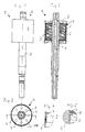
- the rotor 1 shown in detail with reference to FIGS. 1 to 5 exists from a shaft 2 on which a rotor core 3 is fastened.
- the rotor core package 3 is surrounded on the circumference by a molding 4, which is made of two rings butting against each other and aligned with each other 5 exists and which forms the magnet of the rotor.
- the rotor core package 3 is unprocessed on the circumference, the blank 4 closes over the entire surface and flush with this unprocessed outer circumference of the rotor laminated core 3 on and is non-positively connected to it.
- the molding 4 is essentially on its outer circumference surrounded cylindrical sheet metal jacket 6, over the entire outer circumference of the molded article 4 abuts against this and non-positively with this connected is.
- the area between shaft 2 and sheet metal jacket 6 is through two covers 7 completed, each in the between sheet metal jacket 6 and shaft 2 immerse the space formed and are formed by sheet metal parts.
- the Cover 7 have a protruding both outwards and inwards Edge 8 or 9 on which they overlap with the protruding from the molding 4 Part of the sheet metal jacket 6 or the shaft 2 are welded.
- the Detail IV according to Figure 4 clearly shows the outer edge 9, the inside of the sheet metal jacket 6 rests and is welded to it all around. The The sheet metal jacket 6 projects axially beyond the edge 9.
- the detail V according to FIG. 5 shows the welding of the inner edge 8 with the shaft 2, namely via a face lying on the inner edge 8 Fillet weld between shaft 2 and cover 7.
- the cover 7 points over it also eight dome-shaped impressions 10, which for stabilization and serve to avoid vibrations.
- the rotor 1 described above is with respect to the rotor core 3 and of the blank 4, which forms the magnet, through the sheet metal jacket 6 and the cover 7 and the shaft 2 hermetically sealed and ready for use determined in the canned tube of a wet-running engine.
- the shaft 2 contributes to this both sides of the rotor laminated core 3 beyond the cover 7 thrust bearing.
- the long, free shaft end carries, for example, a rotor of a circulation pump.
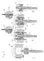
- a first step a the shaft 2 with the on it attached rotor laminated core 3, the cylindrical metal jacket 6 and a Preform 11 - (this is shown in step b) in a pressing tool 12 inserted.
- the preform 11 consists of two of the same size and aligned adjacent rings made of a pre-sintered magnetizable Neodynium-based material. The pre-sintering takes place in such a way that a firm hold of the preform 11, i.e. of the two rings and one there is sufficient dimensional stability, but further deformability is possible, i.e. curing has not yet taken place.
- the components are coordinated so that they lie in one another with play, wherein the preform 11 in its axial length to the rotor core 3 towered over on both sides.
- the space formed between the rotor laminated core 3 and the metal jacket 6 and the diameter of the sheet metal jacket 6 are chosen so that when the preform 11 becomes the molding 4 pressed in FIG. 6c has been reshaped, this not only over the entire surface and non-positively on Outer circumference of the rotor laminated core 3 and on the inner circumference of the laminated shell 6 is present, but also that the sheet metal jacket due to of the forming pressure radially plastically until it rests on the pressing tool 12 deformed and thus calibrated.
- the preform 11 formed blank 4 from two rings, whereby a more uniform material flow should be achieved during the pressing process.
- stamps 13 from above and from below are supportive for application the pressure forces provided.
- the molding or the preform can in principle also be formed in one piece or can consist of several segments.
Landscapes
- Engineering & Computer Science (AREA)
- Manufacturing & Machinery (AREA)
- Power Engineering (AREA)
- Manufacture Of Motors, Generators (AREA)
- Permanent Field Magnets Of Synchronous Machinery (AREA)
- Iron Core Of Rotating Electric Machines (AREA)
Priority Applications (5)
| Application Number | Priority Date | Filing Date | Title |
|---|---|---|---|
| EP01104790A EP1237261B1 (fr) | 2001-02-27 | 2001-02-27 | Procédé pour la production d'un rotor encapsulé d'un moteur à aimant permanent |
| DE50101980T DE50101980D1 (de) | 2001-02-27 | 2001-02-27 | Verfahren zur Herstellung eines gekapselten Rotors eines Permanentmagnetmotors |
| US10/468,929 US6958555B2 (en) | 2001-02-27 | 2002-02-27 | Method for producing an encased rotor of a permanent magnet |
| PCT/EP2002/002087 WO2002069478A1 (fr) | 2001-02-27 | 2002-02-27 | Procede de fabrication d'un rotor blinde d'un moteur a aimant permanent |
| JP2002568490A JP4503234B2 (ja) | 2001-02-27 | 2002-02-27 | 永久磁石モータのキャンド・ロータの製造方法 |
Applications Claiming Priority (1)
| Application Number | Priority Date | Filing Date | Title |
|---|---|---|---|
| EP01104790A EP1237261B1 (fr) | 2001-02-27 | 2001-02-27 | Procédé pour la production d'un rotor encapsulé d'un moteur à aimant permanent |
Publications (2)
| Publication Number | Publication Date |
|---|---|
| EP1237261A1 true EP1237261A1 (fr) | 2002-09-04 |
| EP1237261B1 EP1237261B1 (fr) | 2004-04-14 |
Family
ID=8176618
Family Applications (1)
| Application Number | Title | Priority Date | Filing Date |
|---|---|---|---|
| EP01104790A Expired - Lifetime EP1237261B1 (fr) | 2001-02-27 | 2001-02-27 | Procédé pour la production d'un rotor encapsulé d'un moteur à aimant permanent |
Country Status (5)
| Country | Link |
|---|---|
| US (1) | US6958555B2 (fr) |
| EP (1) | EP1237261B1 (fr) |
| JP (1) | JP4503234B2 (fr) |
| DE (1) | DE50101980D1 (fr) |
| WO (1) | WO2002069478A1 (fr) |
Families Citing this family (11)
| Publication number | Priority date | Publication date | Assignee | Title |
|---|---|---|---|---|
| US7709988B2 (en) * | 2006-04-07 | 2010-05-04 | General Electric Company | Methods and apparatus for using an electrical machine to transport fluids through a pipeline |
| EP2056432B1 (fr) * | 2007-10-29 | 2015-04-15 | Grundfos Management A/S | Embrayage magnétique |
| CN101860133B (zh) * | 2010-04-27 | 2012-06-06 | 广东伊莱斯电机有限公司 | 一种交流永磁伺服电机定子的加工方法及装置 |
| GB201014074D0 (en) | 2010-08-24 | 2010-10-06 | Dyson Technology Ltd | Rotor for an electrical machine |
| GB201014073D0 (en) | 2010-08-24 | 2010-10-06 | Dyson Technology Ltd | Rotor core assembly |
| GB2485149B (en) * | 2010-11-02 | 2014-11-05 | Dyson Technology Ltd | Method of manufacturing a magnet assembly |
| DE102012100693A1 (de) | 2012-01-27 | 2013-08-01 | Ms-Schramberg Holding Gmbh & Co. Kg | Verfahren zur Auskleidung eines Hohlkörpers mit einem aus pulverförmigem Material gepressten Formkörper |
| CN104475793B (zh) * | 2014-12-16 | 2017-02-22 | 福建永强力加动力设备有限公司 | 发电机定子铁心车削工装 |
| US12191722B2 (en) | 2019-05-31 | 2025-01-07 | MagniX USA, Inc. | High-torque electric motor assembly |
| DE102020115470A1 (de) | 2020-06-10 | 2021-12-16 | Bühler Motor GmbH | Verfahren zur Herstellung eines Rotors eines Elektromotors |
| CN115276337A (zh) * | 2022-04-29 | 2022-11-01 | 重庆虎溪电机工业有限责任公司 | 一种抗强冲击振动结构的永磁同步电机的制作方法 |
Citations (3)
| Publication number | Priority date | Publication date | Assignee | Title |
|---|---|---|---|---|
| US4713877A (en) * | 1986-02-05 | 1987-12-22 | Ford Motor Company | Method of forming permanent magnets within a motor yoke |
| US4818305A (en) * | 1980-12-18 | 1989-04-04 | Magnetfabrik Bonn Gmbh | Process for the production of elongated articles, especially magnets, from hard powdered materials |
| US5495658A (en) * | 1993-07-16 | 1996-03-05 | Sanden Corp. | Method of making cylindrical ferromagnetic body and cover assembly for rotor of DC motor |
Family Cites Families (11)
| Publication number | Priority date | Publication date | Assignee | Title |
|---|---|---|---|---|
| US4104787A (en) * | 1977-03-21 | 1978-08-08 | General Motors Corporation | Forming curved wafer thin magnets from rare earth-cobalt alloy powders |
| US4126933A (en) * | 1977-07-14 | 1978-11-28 | Carrier Corporation | Method for assembling a permanent magnet rotor |
| US4845837A (en) * | 1986-10-06 | 1989-07-11 | Emerson Electric Co. | Method of making permanent magnet assembly |
| US4918802A (en) * | 1989-02-06 | 1990-04-24 | Franklin Electric Co., Inc. | Method and apparatus for making permanent magnet rotors |
| US6348752B1 (en) * | 1992-04-06 | 2002-02-19 | General Electric Company | Integral motor and control |
| JP3023576B2 (ja) * | 1992-04-15 | 2000-03-21 | アイチ−エマソン電機株式会社 | 永久磁石付回転子 |
| US5288447A (en) * | 1993-02-22 | 1994-02-22 | General Electric Company | Method of making permanent magnet rotors |
| US5627423A (en) * | 1993-06-11 | 1997-05-06 | Askoll S.P.A. | Permanent-magnet rotor for electric motors and method of manufacturing the same |
| US5687471A (en) * | 1994-06-14 | 1997-11-18 | Honda Giken Kogyo Kabushiki Kaisha | Method of and apparatus for covering rotor magnets |
| WO1998031497A1 (fr) * | 1997-01-20 | 1998-07-23 | Kabushiki Kaisha Meidensha | Structure d'assemblage unifiee entre un aimant d'un metal des terres rares et une matiere metallique et procede d'assemblage |
| CN100379122C (zh) * | 1998-01-20 | 2008-04-02 | 扎纳西电机公司 | 换向式电机的转子及其批量生产的方法 |
-
2001
- 2001-02-27 DE DE50101980T patent/DE50101980D1/de not_active Expired - Lifetime
- 2001-02-27 EP EP01104790A patent/EP1237261B1/fr not_active Expired - Lifetime
-
2002
- 2002-02-27 WO PCT/EP2002/002087 patent/WO2002069478A1/fr not_active Ceased
- 2002-02-27 JP JP2002568490A patent/JP4503234B2/ja not_active Expired - Lifetime
- 2002-02-27 US US10/468,929 patent/US6958555B2/en not_active Expired - Lifetime
Patent Citations (3)
| Publication number | Priority date | Publication date | Assignee | Title |
|---|---|---|---|---|
| US4818305A (en) * | 1980-12-18 | 1989-04-04 | Magnetfabrik Bonn Gmbh | Process for the production of elongated articles, especially magnets, from hard powdered materials |
| US4713877A (en) * | 1986-02-05 | 1987-12-22 | Ford Motor Company | Method of forming permanent magnets within a motor yoke |
| US5495658A (en) * | 1993-07-16 | 1996-03-05 | Sanden Corp. | Method of making cylindrical ferromagnetic body and cover assembly for rotor of DC motor |
Also Published As
| Publication number | Publication date |
|---|---|
| EP1237261B1 (fr) | 2004-04-14 |
| US6958555B2 (en) | 2005-10-25 |
| JP2004521590A (ja) | 2004-07-15 |
| DE50101980D1 (de) | 2004-05-19 |
| WO2002069478A1 (fr) | 2002-09-06 |
| JP4503234B2 (ja) | 2010-07-14 |
| US20040111869A1 (en) | 2004-06-17 |
Similar Documents
| Publication | Publication Date | Title |
|---|---|---|
| DE2433770C2 (de) | Verfahren zum Herstellen eines Stators für eine elektrische Maschine | |
| EP3289669B1 (fr) | Machine électrique sans boîtier | |
| EP1237261B1 (fr) | Procédé pour la production d'un rotor encapsulé d'un moteur à aimant permanent | |
| DE102008043488A1 (de) | Welle-Nabe-Bauteil sowie Verfahren zur Herstellung eines derartigen Bauteils | |
| DE102017203833A1 (de) | Flüssigkeitspumpe | |
| DE102013211816B4 (de) | Elektromagnetische Schaltvorrichtung sowie Verfahren zu ihrer Herstellung | |
| WO2021233673A1 (fr) | Machine électrique à refroidissement de la tête d'enroulement | |
| DE19536027C2 (de) | Planetengetriebe-Geschwindigkeitsreduzierer und Herstellungsverfahren für einen Planetengetriebe-Haltestift für dasselbe | |
| EP3244425A1 (fr) | Tube polaire pour électroaimants et électrovannes et procédé et dispositif destinés à sa fabrication | |
| EP3053253B1 (fr) | Moteur électrique | |
| EP3261221B1 (fr) | Rotor pour une machine électrique, machine électrique comprenant le rotor et procédé de fabrication du rotor | |
| DE102009054191A1 (de) | Vorrichtung und Verfahren zur Befestigung von Magneten auf einen Rotor | |
| EP1519468A2 (fr) | Machine électrique à refroidissement fluidique et méthode de fabrication d'une telle machine | |
| DE102006024767A1 (de) | Verfahren und Vorrichtung zum Verbinden eines Kunststoffdeckels mit einem Metallgehäuse | |
| EP3261224B1 (fr) | Machine électrique comprenant un rotor et procédé de fabrication de la machine électrique | |
| DE102010003354A1 (de) | Einbau-Lenkungsmotoranordnung und Lenkungsvorrichtung | |
| DE69401828T2 (de) | Verfahren zur Herstellung eines Läufers eines rotierenden elektrischen Kollektors | |
| DE102019001273A1 (de) | Stator eines Elektromotors, Elektromotor und Verfahren zum Herstellen eines Stators | |
| DE102004058414A1 (de) | Rotoranordnung und Verfahren und Vorrichtung zur Herstellung einer Rotoranordnung | |
| WO2020007707A1 (fr) | Ensemble moteur comportant une chemise d'entrefer | |
| EP3454349A1 (fr) | Procédé de fabrication d'un raccordement induit magnétique-poussoir et raccordement induit magnétique-poussoir pour un actionneur linéaire | |
| DE102019214301A1 (de) | Fluidpumpe mit freiliegendem axial fixierten Rückschlussring | |
| EP3591812B1 (fr) | Moteur électrique et procédé de fabrication d'un moteur électrique | |
| DE102021209396A1 (de) | Rotor für einen Elektromotor | |
| EP1516408B1 (fr) | Moteur electrique, notamment moteur sans balais, a rotor excite par aimant permanent et procede permettant de le produire |
Legal Events
| Date | Code | Title | Description |
|---|---|---|---|
| PUAI | Public reference made under article 153(3) epc to a published international application that has entered the european phase |
Free format text: ORIGINAL CODE: 0009012 |
|
| AK | Designated contracting states |
Kind code of ref document: A1 Designated state(s): AT BE CH CY DE DK ES FI FR GB GR IE IT LI LU MC NL PT SE TR |
|
| AX | Request for extension of the european patent |
Free format text: AL;LT;LV;MK;RO;SI |
|
| 17P | Request for examination filed |
Effective date: 20021205 |
|
| AKX | Designation fees paid |
Designated state(s): DE FR GB IT |
|
| GRAP | Despatch of communication of intention to grant a patent |
Free format text: ORIGINAL CODE: EPIDOSNIGR1 |
|
| GRAS | Grant fee paid |
Free format text: ORIGINAL CODE: EPIDOSNIGR3 |
|
| GRAA | (expected) grant |
Free format text: ORIGINAL CODE: 0009210 |
|
| AK | Designated contracting states |
Kind code of ref document: B1 Designated state(s): DE FR GB IT |
|
| REG | Reference to a national code |
Ref country code: GB Ref legal event code: FG4D Free format text: NOT ENGLISH |
|
| REF | Corresponds to: |
Ref document number: 50101980 Country of ref document: DE Date of ref document: 20040519 Kind code of ref document: P |
|
| REG | Reference to a national code |
Ref country code: IE Ref legal event code: FG4D Free format text: GERMAN |
|
| GBT | Gb: translation of ep patent filed (gb section 77(6)(a)/1977) |
Effective date: 20040712 |
|
| REG | Reference to a national code |
Ref country code: IE Ref legal event code: FD4D |
|
| ET | Fr: translation filed | ||
| PLBE | No opposition filed within time limit |
Free format text: ORIGINAL CODE: 0009261 |
|
| STAA | Information on the status of an ep patent application or granted ep patent |
Free format text: STATUS: NO OPPOSITION FILED WITHIN TIME LIMIT |
|
| PG25 | Lapsed in a contracting state [announced via postgrant information from national office to epo] |
Ref country code: IT Free format text: LAPSE BECAUSE OF NON-PAYMENT OF DUE FEES;WARNING: LAPSES OF ITALIAN PATENTS WITH EFFECTIVE DATE BEFORE 2007 MAY HAVE OCCURRED AT ANY TIME BEFORE 2007. THE CORRECT EFFECTIVE DATE MAY BE DIFFERENT FROM THE ONE RECORDED. Effective date: 20050227 |
|
| 26N | No opposition filed |
Effective date: 20050117 |
|
| PGRI | Patent reinstated in contracting state [announced from national office to epo] |
Ref country code: IT Effective date: 20091201 |
|
| REG | Reference to a national code |
Ref country code: FR Ref legal event code: PLFP Year of fee payment: 16 |
|
| REG | Reference to a national code |
Ref country code: FR Ref legal event code: PLFP Year of fee payment: 17 |
|
| REG | Reference to a national code |
Ref country code: FR Ref legal event code: PLFP Year of fee payment: 18 |
|
| PGFP | Annual fee paid to national office [announced via postgrant information from national office to epo] |
Ref country code: IT Payment date: 20200221 Year of fee payment: 20 Ref country code: GB Payment date: 20200225 Year of fee payment: 20 Ref country code: DE Payment date: 20200226 Year of fee payment: 20 |
|
| PGFP | Annual fee paid to national office [announced via postgrant information from national office to epo] |
Ref country code: FR Payment date: 20200219 Year of fee payment: 20 |
|
| REG | Reference to a national code |
Ref country code: DE Ref legal event code: R071 Ref document number: 50101980 Country of ref document: DE |
|
| REG | Reference to a national code |
Ref country code: GB Ref legal event code: PE20 Expiry date: 20210226 |
|
| PG25 | Lapsed in a contracting state [announced via postgrant information from national office to epo] |
Ref country code: GB Free format text: LAPSE BECAUSE OF EXPIRATION OF PROTECTION Effective date: 20210226 |