EP1237180A2 - Appareil à vide et appareil de transfert - Google Patents
Appareil à vide et appareil de transfert Download PDFInfo
- Publication number
- EP1237180A2 EP1237180A2 EP02251435A EP02251435A EP1237180A2 EP 1237180 A2 EP1237180 A2 EP 1237180A2 EP 02251435 A EP02251435 A EP 02251435A EP 02251435 A EP02251435 A EP 02251435A EP 1237180 A2 EP1237180 A2 EP 1237180A2
- Authority
- EP
- European Patent Office
- Prior art keywords
- tape
- work
- transfer
- piece
- transfer apparatus
- Prior art date
- Legal status (The legal status is an assumption and is not a legal conclusion. Google has not performed a legal analysis and makes no representation as to the accuracy of the status listed.)
- Withdrawn
Links
Images

Classifications
-
- H—ELECTRICITY
- H10—SEMICONDUCTOR DEVICES; ELECTRIC SOLID-STATE DEVICES NOT OTHERWISE PROVIDED FOR
- H10P—GENERIC PROCESSES OR APPARATUS FOR THE MANUFACTURE OR TREATMENT OF DEVICES COVERED BY CLASS H10
- H10P95/00—Generic processes or apparatus for manufacture or treatments not covered by the other groups of this subclass
-
- H—ELECTRICITY
- H10—SEMICONDUCTOR DEVICES; ELECTRIC SOLID-STATE DEVICES NOT OTHERWISE PROVIDED FOR
- H10P—GENERIC PROCESSES OR APPARATUS FOR THE MANUFACTURE OR TREATMENT OF DEVICES COVERED BY CLASS H10
- H10P72/00—Handling or holding of wafers, substrates or devices during manufacture or treatment thereof
- H10P72/70—Handling or holding of wafers, substrates or devices during manufacture or treatment thereof for supporting or gripping
- H10P72/76—Handling or holding of wafers, substrates or devices during manufacture or treatment thereof for supporting or gripping using mechanical means, e.g. clamps or pinches
- H10P72/7602—Handling or holding of wafers, substrates or devices during manufacture or treatment thereof for supporting or gripping using mechanical means, e.g. clamps or pinches the wafers being placed on a robot blade or gripped by a gripper for conveyance
-
- H—ELECTRICITY
- H10—SEMICONDUCTOR DEVICES; ELECTRIC SOLID-STATE DEVICES NOT OTHERWISE PROVIDED FOR
- H10P—GENERIC PROCESSES OR APPARATUS FOR THE MANUFACTURE OR TREATMENT OF DEVICES COVERED BY CLASS H10
- H10P72/00—Handling or holding of wafers, substrates or devices during manufacture or treatment thereof
- H10P72/30—Handling or holding of wafers, substrates or devices during manufacture or treatment thereof for conveying, e.g. between different workstations
- H10P72/33—Handling or holding of wafers, substrates or devices during manufacture or treatment thereof for conveying, e.g. between different workstations into and out of processing chamber
- H10P72/3302—Mechanical parts of transfer devices
-
- Y—GENERAL TAGGING OF NEW TECHNOLOGICAL DEVELOPMENTS; GENERAL TAGGING OF CROSS-SECTIONAL TECHNOLOGIES SPANNING OVER SEVERAL SECTIONS OF THE IPC; TECHNICAL SUBJECTS COVERED BY FORMER USPC CROSS-REFERENCE ART COLLECTIONS [XRACs] AND DIGESTS
- Y10—TECHNICAL SUBJECTS COVERED BY FORMER USPC
- Y10S—TECHNICAL SUBJECTS COVERED BY FORMER USPC CROSS-REFERENCE ART COLLECTIONS [XRACs] AND DIGESTS
- Y10S414/00—Material or article handling
- Y10S414/135—Associated with semiconductor wafer handling
Definitions
- the present invention relates to a vacuum apparatus and a transfer apparatus used for a semiconductor manufacturing apparatus, a manufacturing apparatus for a flat panel display etc. or the like.
- a work-piece such as a silicon wafer is subject to various kinds of processes such as etching, CVD, ashing, RTP, and dry cleaning. These processes need to be conducted in a clean and high vacuum, and, in order to obtain this vacuum environment, a large-scale apparatus is used when the work-piece is transferred to and transferred from the vacuum apparatus.
- a load chamber for transfer to the vacuum chamber the work-piece from the outside under the atmospheric pressure and an unload chamber for transfer from the vacuum chamber the work-piece having finished processes to the outside.
- Fig. 9 shows an example of this vacuum apparatus.
- a load chamber 701 and an unload chamber 702 each are arranged in contact with wall surfaces of a transfer chamber 703, which is located in the center of the apparatus.
- the transfer chamber 703 is, as shown in the figure, formed into a flat surface of a polygon shape, and is provided with a vacuum robot 704 in its center.
- Process chambers 705, 706 are arranged on the other wall surfaces.
- the process chambers 705, 706 are chambers for performing for the work-piece processing such as CVD.
- gate valves 707, 708, 709, 710 each having airtight property in the walls which divide the load chamber 701, the unload chamber 702, and the process chambers 705, 706 from the transfer chamber 703.
- the gate valve 707, 708, 709, or 710 is opened.
- the gate valve is closed to keep airtightness of each other.
- doors 711, 712 each having airtight property between the load chamber 701 and the unload chamber 702, respectively, and the outside.
- the door 711 or 712 is opened.
- the external robot finishes transfer the work-piece the door is closed, exhaust is performed and pressure is reduced to a vacuum, thereby keeping airtightness with the atmosphere.
- the vacuum robot 704 turns holding the work-piece, faces this gate valve 709 and stops its motion. Subsequently, the vacuum robot 704 accommodates the work-piece inside the process chamber 705 having finished the first process with a second holder hand thereof (not shown), and transfers to the inside of the process chamber 705 the work-piece before going through the first process, which is held by the first holder hand. Then, the gate valve 709 is closed, and the work-piece is subject to processing of the first process inside the closed process chamber 705.
- the work-piece subsequently finishes processing of a second process (another process chamber 706), and in a state that the vacuum robot 704 holds the work-piece having finished the processing, the vacuum robot 704 faces the unload chamber 702.
- the gate valve 708 between the transfer chamber 703 and the unload chamber 702 is opened, and the work-piece is transferred to the unload chamber 702.
- the gate valve 708 is closed and the door 712 is opened by making the inside of the unload chamber 702 be in the atmospheric pressure, and the work-piece having finished the processing is taken out to the outside by the external robot or the like.
- the vacuum apparatus shown in Fig. 9 is suitable for mass production as described above.
- the operation of transfer the work-piece to and from the process chamber is complicated, and the apparatus becomes large-scale, the cost of which is higher and requires wide space.
- the vacuum robot 805 turns holding the work-piece, faces this gate valve 807 and stops its motion. Subsequently, the vacuum robot 805 accommodates the work-piece inside the process chamber 806 having finished processing with a second holder hand thereof (not shown), and transfers to the inside of the process chamber 806 the work-piece before going through the processing, which is held. Then, the gate valve 807 is closed, and the work-piece is subject to the processing inside the closed process chamber 806.
- a new work-piece is set in the load/unload chamber 801, and pressure in the load/unload chamber 801 is reduced to a vacuum.
- the gate valve 804 is opened, and the work-piece having finished the processing, which is held by the second holder hand of the vacuum robot 805, is transferred to the load/unload chamber 801.
- the first holder hand makes the new work-piece be accommodated in the transfer chamber 802, and the gate valve 804 is closed.
- the load/unload chamber 801 is made to be in the atmospheric pressure, and the door 803 between the outside and the load/unload chamber 801 is opened. Then, the external robot or the like takes out to the outside the work-piece having finished the processing.
- the vacuum apparatus shown in Fig. 10 for performing loading and unloading in one chamber is simpler, obtained at lower cost and more space-saving as compared with the vacuum apparatus shown in Fig. 9.
- the transfer chamber and the load/unload chamber there are the transfer chamber and the load/unload chamber, and besides the vacuum robot in the transfer chamber requires a turning mechanism. Therefore, wide space is still required.
- a transfer apparatus for a vacuum apparatus for example, as disclosed in Japanese Patent Application Laid-open No. Hei 5-26318, there is known a frog-leg type transfer apparatus, in which two arms connected in series in its joint are made to be a pair, a transferred body support portion is attached to the tip end of the one of the arms and the rear end of the other arm is attached to a base, to thereby move the transferred body support portion by bending the arm.
- This frog-leg type transfer apparatus does not have a turning mechanism differing from the vacuum robot. However, since the arm is bent in its shrunk state, space for portions overhanging in its left and right is required.
- the present invention is made in view of solving the above-mentioned problem, and an object of the present invention is to provide a vacuum apparatus used for a semiconductor manufacturing process and the like, which is space-saving and provided at low cost, and a transfer apparatus, which is suitable for use in this vacuum apparatus or in other narrow space and is space-saving.
- the vacuum apparatus of the present invention comprises: a process chamber for performing for a work-piece processing; and a transfer chamber connected to the process chamber via a gate valve for accommodating a transfer apparatus to an inside thereof, in which the transfer apparatus comprises: a tape provided with a work-piece holder hand in its tip end portion, in which the tip end portion extends to an inside of the process chamber in an extended state extending in a longitudinal direction, and is accommodated inside the transfer apparatus in a shrunk state; and feeding means for feeding this tape in the longitudinal direction.
- the transfer tape is a tape made of an elastic material having a curved cross section, certain rigidity is given to a thickness direction of the tape. If the thickness direction of the transfer tape is made to be perpendicular, the rigidity for receiving load increases and the tape becomes hard to be bent.
- the feeding means is a driving pulley, it becomes easy to control a feeding speed.
- the tape is symmetrically provided as a pair and both tip end portions of this pair of transfer tapes are provided with one work-piece holder hand, the transfer and supporting of the work-piece holder hand becomes further stable.
- magnets are provided in the inside and the outside of this tape accommodating cylinder. By making the magnet of the inside follow movement of the magnet of the outside, it becomes possible to move the tape from the outside of the vacuum apparatus.
- this linear guide portion has a plurality of slide portions between the base and the tip member, it becomes possible to make a moving distance of the work-piece holder hand longer.
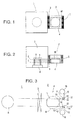
- Fig. 1 is a diagram for explaining a construction of a vacuum apparatus in accordance with First embodiment of the present invention.
- Reference numeral 1 indicates a process chamber for performing for a work-piece (a wafer in this embodiment) W processing such as CVD.
- Reference numeral 2 indicates a transfer chamber connected to the process chamber 1 via a gate valve 3.
- a transfer apparatus 4 is set in this transfer chamber 2.
- a blocking door 5 for loading/unloading the work-piece is provided between the transfer chamber 2 and the outside.
- the transfer apparatus 4 is an apparatus for transfer to the process chamber 1 the work-piece W loaded from the outside and transfer back to the transfer chamber 2 the work-piece having finished the processing.
- the transfer apparatus 4 is constructed such that: when the gate valve 3 is opened, its tape is pulled out successively and made to be in an extended state to thereby perform transfer to and transfer from of the work-piece; and when the gate valve 3 is closed, the tape is made to be in a shrunk state to thereby be accommodated inside the transfer chamber 2.
- the blocking door 5 opens when the work-piece W is loaded from the outside and the work-piece W is unloaded to the outside. In other time, the blocking door 5 closes to block the transfer chamber 2 from the air.
- Fig. 2 is a diagram for explaining a side surface of Fig. 1.
- holder hand transfer bodies 6, 7 composed of a pair of tapes.
- These holder hand transfer bodies 6, 7 are provided with a work-piece holder hand in their tip end portions and, as described later in detail, are constructed so as to move the work-piece holder hand in left and right directions in the figure.
- reference numeral 8 in Fig. 2 indicates a susceptor for disposing the work-piece W to perform the processing
- reference numeral 9 indicates lift pins for delivering the work-piece W between the work-piece holder hand of the transfer apparatus 4 and the susceptor 8.
- Fig. 3 is a plan view for schematically showing the holder hand transfer body 6 of the transfer apparatus 4 disposed inside the vacuum apparatus
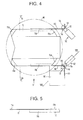
- Fig. 4 is a plan view for showing the transfer apparatus in a state which makes a tape in Fig. 3 be in a shrunk state and returns the work-piece holder hand
- Fig. 5 and Fig. 6 are a view seen from an arrow V and a view seen from an arrow VI of Fig. 4, respectively
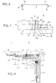
- Fig. 7 is a cross-sectional side view for showing feeding means of a tape in Fig. 4.
- the holder hand transfer body 6 is composed of a pair of tapes 10, 10 disposed parallelly, and a work-piece holder hand 11 is attached to the tip end portions of these tapes 10, 10. Also, on the rear end sides of the tapes 10, 10, a pair of feeding means 12, 12 for feeding the tapes in a longitudinal direction is provided. This pair of feeding means 12, 12 operates in synchronism with each other.
- the cross-sectional shape of the tape 10 is made to be a curved cross section in this embodiment, a used material of which is a nickel-base spring member made of metal, which is high in durability and is resistant to rust.
- the curved cross section increases rigidity of the tape, and, as in this embodiment, when a width direction of the tape matches upper and lower directions in its use, the work-piece holder hand 11 and the work-piece W disposed thereon are sufficiently supported.
- the thickness of the tape 10 and the degree of the curvature can be selected according to the weight of the work-piece to be holder handled. Note that, provided that the material has sufficient rigidity and elasticity, the curved cross sectional shape is not necessarily essential, and even a non-metallic material can be used.
- the work-piece is a semiconductor wafer held by the work-piece holder hand 11.
- support portions 11a, 11a, ... for supporting four points in an outer periphery of the wafer W are protruded upward and attaching portions 11b, 11b to the tape 10 are protruded downward.
- the feeding means 12 is a driving pulley 13 for winding and hanging the tape 10 to drive the tape 10 in its longitudinal direction in this embodiment.
- a pressing/direction-converting pulley 15 presses the tape 10 from its back surface to the driving pulley 13 side.
- Reference numerals 14, 14 indicate guide pulleys for guiding the tape 10 in the front and the rear of a direction-converting portion of the tape 10.
- the rear end side of the tape 10 is bent by 90° along the driving pulley 13 by the pressing/direction-converting pulley 15, and is wound by winding means 16 of a reel structure.
- This winding means 16 is constructed such that the end of the tape 10 is fixed to a winding core inside its case and the tape 10 is wound due to a spring action.
- a shaft 13a of the driving pulley 13 is protruded to the outside of the transfer chamber 2, which is the lower side of the transfer apparatus 4, and is subject to normal and reverse rotation drive by a not-shown motor.
- reference numeral 17 indicates a bearing which is projectingly provided from a bottom surface 18 of the transfer apparatus to the inside, and this bearing 17 holds the shaft 13a of the driving pulley in a rotatable manner.
- a seal 19 for an O ring is provided in the shaft 13a inside the bottom surface 18, and the seal 19 keeps airtightness in the transfer chamber 2.
- a magnetic fluid seal may be used instead of this O ring.
- a vacuum motor or an ultrasonic motor which can be used in a vacuum, is used for a driving source of the pulley 13 and this is set inside the transfer chamber 2, thereby making it possible to eliminate the seal.
- a pulley surface of the driving pulley 13 is formed into a drum shape corresponding to the curved cross section of the tape 10.
- Each pulley surface of the guide pulley 14 and the pressing/direction-converting pulley 15 is formed into a straight cylindrical shape.
- the pulley surface of the driving pulley 13 is formed into a drum shape having a smaller radius of curvature than that of the curved cross sectional shape of the tape 10, and each pulley surface of the guide pulley 14 and the pressing/direction-converting pulley 15 is formed into slightly a drum shape to reduce a contact area with the tape 10, to thereby eliminate friction accompanied with deformation of the curved cross sectional shape in bending the tape 10.
- the pressing/direction-converting pulley 15 is mainly supported by a support shaft 20 and thus can freely rotate.
- the support shaft 20 is fixed to a support shaft seat 21.
- a pin 22 is protruded from the side of this support shaft seat 21, this pin 22 thrusts a guide hole 23a of a pressing means base 23, and a spring 24 elastically provided between the pressing means base 23 and the pin 22 pushes the pin 22 to the driving pulley 13 side, such that the pressing/direction-converting pulley 15 presses and sandwiches the transfer pulley 10 between the driving pulley 13.
- reference symbol 22a indicates an E ring which is fit into an outer peripheral groove of the pin 22, and the spring 24 is, more specifically, elastically provided between this E ring and the pin 22.
- the guide pulley 14 is disposed at the front and the rear of the pressing/direction-converting pulley 15, with a space equal to the thickness of the tape 10 provided, and is rotatable similarly to the pressing/direction-converting pulley 15.
- the holder hand transfer body 6 of an upper stage is also constructed in the same manner.
- the holder hand transfer body 7 of a lower stage is also constructed in the same manner.
- the tapes 10, 10 of both the upper stage and the lower stage are accommodated inside the transfer chamber together with the work-piece holder hand 11 and are in a shrunk state as shown in Fig. 4. At this time, the rear end sides of the tapes 10, 10 are wound to the inside of the winding means 16, 16.
- the work-piece W is smoothly delivered while the lift pins 9, 9 go up and down by a not-shown elevating mechanism in cooperation with coming in and out of the object in the left and right of the work-piece holder hand 11.
- the driving pulley 13 rotates in a reverse direction. This rotation in the reverse direction pulls back the tapes 10, 10 successively. Then the work-piece holder hand 11 is pulled back to the inside of the transfer chamber 2, and the rear end portion sides of the tapes 10, 10 are wound to the inside of the winding means 16.
- the transfer chamber 2 can be compactly constructed. Further, since the holder hand transfer bodies 6, 7 do not go up and down, the height of the transfer chamber 2 can be lowered and a volume in the transfer chamber can be extremely reduced. If the volume in the transfer chamber is small, it shortens exhaust time upon making the transfer chamber 2 be in a vacuum and vent time upon making the transfer chamber 2 return to the air.
- Fig. 8 is a cross-sectional side view for showing second embodiment of the present invention. It is the same as in First embodiment that the holder hand transfer bodies are constructed in two stages of an upper stage and a lower stage in second embodiment.
- Second embodiment differs from first embodiment in the following points: the holder hand transfer body 6 (or 7) has a linear guide portion 26 of two stages, and this linear guide portion 26 attaches the work-piece holder hand 11 to its tip end and supports the object, to thereby make the work-piece holder hand 11 move feed and astern while the tape 10 extends and shrinks the linear guide portion 26 of two stages; a width direction of the tape 10 is made to match a horizontal direction, and a direction changing means 25 rotates the rear end side of the tape 10 by 90° downward to thereby perpendicularly lead the tape 10 to an empty space under a support base of the vacuum apparatus; and a magnet which moves linearly is used as a driving means.
- the direction changing means 25 is composed of pulleys 25a, 25b, 25c and 25d disposed in the same arrangement as the feeding means 12 in First embodiment. However, these pulleys 25a - 25d are provided not for driving the tape 10 but for securely changing the direction of the tape 10 by 90°. The tape 10 is set so as to be slightly sandwiched between these pulleys.
- Reference numeral 26 indicates a linear guide portion.
- This linear guide portion 26 is, in this embodiment, constructed to be a two-stage extendable type, which is composed of a base portion linear guide 27, a middle portion linear guide 28 and a tip member 29.
- the base portion linear guide 27 is attached to a transfer apparatus bottom surface (base) 18.
- the middle portion linear guide 28 slides by means of a track base 28a disposed on a linear guide rail 27a on this base portion linear guide 27, and the tip member 29 slides by means of a track base 29a disposed on a linear guide rail 28b on the middle portion linear guide 28.
- the number of expansion and shrinkage stages of the linear guide portion 26 can be appropriately selected according to a ratio of a transfer distance to size of the transfer apparatus.
- the tip end portion of the tape 10 which is disposed such that its width direction becomes horizontal and a convex portion of the curved cross section becomes the upper side, is attached to the tip member 29 and also indirectly to the work-piece holder hand 11 in this embodiment. That is, the work-piece holder hand 11 is attached to both the tape 10 and the tip member 29 of the linear guide portion 26.
- Reference numeral 30 indicates a tape accommodating cylinder.
- This tape accommodating cylinder 30 accommodates the rear end portion of the tape 10 when the tape 10 is reversed, and is extendedly provided from the rear portion of the transfer apparatus 4 in an empty space under the support base of the vacuum apparatus to the downward.
- the inside of the tape accommodating cylinder 30 is connected to the transfer chamber 2 and becomes in the same atmospheric pressure as that in the transfer chamber 2.
- Reference numeral 31 indicates feeding means of the tape 10.
- This feeding means 31 is composed of a guide rail 32 perpendicularly provided along the outside of the tape accommodating cylinder 30, a track base 33 which is movable in a perpendicular direction through a guide by this guide rail 32, a driving magnet 34 fixed to this track base 33, a slider 35 fixed to the rear end portion of the tape 10 and capable of sliding in the internal cylinder of the tape accommodating cylinder 30, a driven magnet 36 fixed to this slider 35 and, although not shown, a vertical drive mechanism for driving the track base 33 in upward and downward directions .
- this vertical drive mechanism a mechanism of a motor and a feeding screw, an air cylinder, a motor and a belt or the like is used.
- the driven magnet 36 and the driving magnet 34 are sucked to each other, and when the driving magnet 34 moves upward and downward, the driven magnet 36 also moves upward and downward following this.
- a support roller 37 is provided in the middle portion linear guide 28 of the linear guide portion 26 for supporting the tape 10 from the upward and downward directions. Note that, if rigidity of the tape 10 is strong, the support roller 37 can be omitted.
- the driving magnet 34 moves downward to pull down the driven magnet 36, and as shown in a double-dotted chain line in the figure, the rear end portion of the tape 10 is pulled into the tape accommodating cylinder 30 to make the tape 10 be in a shrunk state.
- the driving magnet 34 moves upward to pull up the driven magnet 36. Since the tape 10 is made of an elastic material having a curved cross section, in a portion inside the straightly extended tape accommodating cylinder 30 and a portion further than the direction changing means 25, rigidity is high and bending can be prevented, and the tip member 29 of the linear guide portion 26 is pushed out to make the linear guide portion 26 be in an extended state.
- the tape in the same way as the pulley drive, the tape can be driven at a speed corresponding to an environment of use, whereby the work-piece can be smoothly and safely transferred without generating dust.
- the tape accommodating cylinder is formed by projecting the transfer apparatus to an empty space, whereby the transfer apparatus does not overhang in a lateral direction in the shrunk state.
- the linear guide portion can also be shrunk compact. Therefore, as in First embodiment, the transfer chamber can be made compactly, the size of which is not much different from that of the work-piece.
- the driving means by means of the magnets used in Second embodiment is not directly driven by a motor in the outside of the vacuum apparatus as that in First embodiment, and thus there is no need of a seal for keeping airtightness, to thereby further enhance reliability of the vacuum chamber.
- a vacuum apparatus is provided with a work-piece holder hand in a tip end portion of a tape in a transfer apparatus, and a tape is extended in its longitudinal direction to extend the work-piece holder hand to the inside of a process chamber to transfer the same, and when finishing the transfer, the tape is returned to the inside of a transfer chamber, and the returned tape is wound around a reel or pulled inside a tape accommodating cylinder extendedly provided under the floor of the transfer chamber. Therefore, the returned tape does not overhang in left and right, whereby the transfer chamber can be made extremely compact, which is not much larger than the work-piece. Since the volume of the transfer chamber can be small and it becomes easy to make the chamber be in a vacuum, the transfer chamber can serve as the conventional load/unload chamber or both as a load chamber and an unload chamber.
- the number of chambers is small and the whole vacuum apparatus becomes compact, whereby it becomes possible to manufacture the apparatus at low cost with a small setting area.
- This kind of vacuum apparatus is set inside an expensive clean room, and if the setting area of the vacuum apparatus is small, it becomes possible to use a small-scale clean room, which is inexpensive. Thus, extremely high economic effect can be attained.
- a transfer apparatus is provided with a work-piece holder hand in a tip end portion of a tape, the tape slides in its longitudinal direction to overhang and the work-piece holder hand can be transferred for a great distance.
- the returned tape is wound around a reel or pulled inside a tape accommodating cylinder extendedly provided under the apparatus or the like, whereby the returned tape does not overhang in left and right as the conventional turning arm type or the frog-leg type.
- it is suitable to dispose the apparatus in a narrow room or a place around which is crowded.
- the tape When a tape made of an elastic material having a curved cross section is used as the tape, the tape itself becomes high in rigidity, whereby it becomes possible to support and transfer the work-piece without using other support means.
- the returned tape does not overhang in its circumference and extra space is not required.
- the rear end side of the tape is driven by magnets and the tape can be fed from the outside, whereby it becomes easy to keep airtightness when used in a vacuum environment.
- the linear guide portion having rigidity supports the supporting of the holder hand, whereby it becomes possible to overhang the tape longer or to transfer a heavier work-piece.
Landscapes
- Container, Conveyance, Adherence, Positioning, Of Wafer (AREA)
- Manipulator (AREA)
Applications Claiming Priority (2)
| Application Number | Priority Date | Filing Date | Title |
|---|---|---|---|
| JP2001058981A JP2002261147A (ja) | 2001-03-02 | 2001-03-02 | 真空装置および搬送装置 |
| JP2001058981 | 2001-03-02 |
Publications (2)
| Publication Number | Publication Date |
|---|---|
| EP1237180A2 true EP1237180A2 (fr) | 2002-09-04 |
| EP1237180A3 EP1237180A3 (fr) | 2004-12-08 |
Family
ID=18918616
Family Applications (1)
| Application Number | Title | Priority Date | Filing Date |
|---|---|---|---|
| EP02251435A Withdrawn EP1237180A3 (fr) | 2001-03-02 | 2002-02-28 | Appareil à vide et appareil de transfert |
Country Status (4)
| Country | Link |
|---|---|
| US (1) | US6869262B2 (fr) |
| EP (1) | EP1237180A3 (fr) |
| JP (1) | JP2002261147A (fr) |
| KR (1) | KR20020070886A (fr) |
Families Citing this family (6)
| Publication number | Priority date | Publication date | Assignee | Title |
|---|---|---|---|---|
| JP4354675B2 (ja) * | 2002-06-04 | 2009-10-28 | ローツェ株式会社 | 薄板状電子部品クリーン移載装置および薄板状電子製品製造システム |
| JP2004282002A (ja) * | 2003-02-27 | 2004-10-07 | Tokyo Electron Ltd | 基板処理装置及び基板処理方法 |
| GB0413117D0 (en) * | 2004-06-11 | 2004-07-14 | Boc Group Plc | Freeze dryer |
| US7258521B2 (en) * | 2005-05-31 | 2007-08-21 | Scriptpro Llc | Chain-driven robotic arm |
| DE102006003746A1 (de) * | 2006-01-26 | 2007-08-09 | Knorr-Bremse Systeme für Nutzfahrzeuge GmbH | Scheibenbremse, insbesondere für ein Nutzfahrzeug |
| US8413788B2 (en) * | 2011-03-27 | 2013-04-09 | Zhao-Lin Wan | Turning mechanism for polarized electronic components |
Family Cites Families (12)
| Publication number | Priority date | Publication date | Assignee | Title |
|---|---|---|---|---|
| US3968885A (en) * | 1973-06-29 | 1976-07-13 | International Business Machines Corporation | Method and apparatus for handling workpieces |
| US4055259A (en) * | 1976-03-03 | 1977-10-25 | The Perkin-Elmer Corporation | Sample transport with rotary air interlock charging and discharging means |
| JPS5739430U (fr) * | 1980-08-14 | 1982-03-03 | ||
| US4604020A (en) * | 1984-03-26 | 1986-08-05 | Nanometrics Incorporated | Integrated circuit wafer handling system |
| US4609320A (en) * | 1984-06-20 | 1986-09-02 | Rubin Richard H | Flexible workpiece transporter and roller assembly therefor |
| US4699555A (en) * | 1986-05-08 | 1987-10-13 | Micrion Limited Partnership | Module positioning apparatus |
| US4735548A (en) * | 1987-04-20 | 1988-04-05 | Mecs Corporation | Carrier system for clean room |
| US5236295A (en) * | 1990-06-15 | 1993-08-17 | Tokyo Electron Sagami Limited | Arm apparatus for conveying semiconductor wafer and processing system using same |
| KR100297358B1 (ko) * | 1991-07-23 | 2001-11-30 | 히가시 데쓰로 | 플라즈마에칭장치 |
| JP2969034B2 (ja) * | 1993-06-18 | 1999-11-02 | 東京エレクトロン株式会社 | 搬送方法および搬送装置 |
| US5551821A (en) * | 1995-05-08 | 1996-09-03 | Excellon Automation Co. | Worktable loading and unloading apparatus and method |
| US5611248A (en) * | 1995-06-02 | 1997-03-18 | Ats Automation Tooling Systems Inc. | Two-axis robot |
-
2001
- 2001-03-02 JP JP2001058981A patent/JP2002261147A/ja not_active Withdrawn
-
2002
- 2002-02-28 EP EP02251435A patent/EP1237180A3/fr not_active Withdrawn
- 2002-02-28 KR KR1020020011062A patent/KR20020070886A/ko not_active Withdrawn
- 2002-03-01 US US10/090,077 patent/US6869262B2/en not_active Expired - Fee Related
Also Published As
| Publication number | Publication date |
|---|---|
| JP2002261147A (ja) | 2002-09-13 |
| EP1237180A3 (fr) | 2004-12-08 |
| US20020146304A1 (en) | 2002-10-10 |
| US6869262B2 (en) | 2005-03-22 |
| KR20020070886A (ko) | 2002-09-11 |
Similar Documents
| Publication | Publication Date | Title |
|---|---|---|
| US20090084215A1 (en) | Industrial robot | |
| US9859140B2 (en) | Fast swap dual substrate transport for load lock | |
| EP1197988B1 (fr) | Dispositif d' élévateur pour plusieurs plaquettes et procédé | |
| JP3635061B2 (ja) | 被処理体収容ボックスの開閉蓋の開閉装置及び被処理体の処理システム | |
| JP7407163B2 (ja) | 搬送システム、搬送方法および搬送装置 | |
| KR20050040222A (ko) | 기판 운반시스템 및 운반방법 | |
| JPH08119409A (ja) | 集合処理装置 | |
| US10403528B2 (en) | Substrate-processing apparatus and method of manufacturing semiconductor device | |
| JPWO2001006560A1 (ja) | 被処理体収容ボックスの開閉蓋の開閉装置及び被処理体の処理システム | |
| JP2008283215A (ja) | 基板処理装置 | |
| US5549442A (en) | Article transfer apparatus | |
| EP1237180A2 (fr) | Appareil à vide et appareil de transfert | |
| JPH06104326A (ja) | 処理システム | |
| CN113169107B (zh) | 装载锁定腔室 | |
| JP3892494B2 (ja) | 基板搬送装置 | |
| JP4667187B2 (ja) | 基板搬送装置 | |
| KR102581283B1 (ko) | 포드 오프너 | |
| JP2003229466A (ja) | 真空処理装置 | |
| JP2005076845A (ja) | ゲートバルブ | |
| JP2020096032A (ja) | 基板搬送装置 | |
| KR20230048598A (ko) | 산업용 로봇 | |
| JP4437743B2 (ja) | 真空処理装置用開閉機構及び真空処理装置 | |
| JPH0727952B2 (ja) | ウエハ搬送装置 | |
| JPH07107913B2 (ja) | 真空装置内の基板搬送機構 | |
| KR100648403B1 (ko) | 플라즈마 처리장치 |
Legal Events
| Date | Code | Title | Description |
|---|---|---|---|
| PUAI | Public reference made under article 153(3) epc to a published international application that has entered the european phase |
Free format text: ORIGINAL CODE: 0009012 |
|
| AK | Designated contracting states |
Kind code of ref document: A2 Designated state(s): AT BE CH CY DE DK ES FI FR GB GR IE IT LI LU MC NL PT SE TR |
|
| AX | Request for extension of the european patent |
Free format text: AL;LT;LV;MK;RO;SI |
|
| PUAL | Search report despatched |
Free format text: ORIGINAL CODE: 0009013 |
|
| AK | Designated contracting states |
Kind code of ref document: A3 Designated state(s): AT BE CH CY DE DK ES FI FR GB GR IE IT LI LU MC NL PT SE TR |
|
| AX | Request for extension of the european patent |
Extension state: AL LT LV MK RO SI |
|
| 17P | Request for examination filed |
Effective date: 20050429 |
|
| AKX | Designation fees paid |
Designated state(s): DE FR GB |
|
| STAA | Information on the status of an ep patent application or granted ep patent |
Free format text: STATUS: THE APPLICATION IS DEEMED TO BE WITHDRAWN |
|
| 18D | Application deemed to be withdrawn |
Effective date: 20060829 |