EP1237003A2 - Adapter zum Halten eines Probenbehälters zur Erleichterung der Flüssigkeitsstandmessung im Probenbehälter - Google Patents
Adapter zum Halten eines Probenbehälters zur Erleichterung der Flüssigkeitsstandmessung im Probenbehälter Download PDFInfo
- Publication number
- EP1237003A2 EP1237003A2 EP02003179A EP02003179A EP1237003A2 EP 1237003 A2 EP1237003 A2 EP 1237003A2 EP 02003179 A EP02003179 A EP 02003179A EP 02003179 A EP02003179 A EP 02003179A EP 1237003 A2 EP1237003 A2 EP 1237003A2
- Authority
- EP
- European Patent Office
- Prior art keywords
- adapter
- body portion
- sample container
- tapered
- main body
- Prior art date
- Legal status (The legal status is an assumption and is not a legal conclusion. Google has not performed a legal analysis and makes no representation as to the accuracy of the status listed.)
- Withdrawn
Links
- 239000007788 liquid Substances 0.000 title claims abstract description 80
- 238000002604 ultrasonography Methods 0.000 claims abstract description 48
- 238000002592 echocardiography Methods 0.000 claims abstract description 18
- 238000000034 method Methods 0.000 claims description 8
- 239000004033 plastic Substances 0.000 claims description 3
- 238000003466 welding Methods 0.000 claims description 3
- 230000004308 accommodation Effects 0.000 claims 1
- 239000000523 sample Substances 0.000 description 148
- 238000012360 testing method Methods 0.000 description 22
- 210000002966 serum Anatomy 0.000 description 15
- 239000003153 chemical reaction reagent Substances 0.000 description 8
- 238000005259 measurement Methods 0.000 description 6
- 230000032258 transport Effects 0.000 description 5
- 238000013459 approach Methods 0.000 description 2
- 230000000295 complement effect Effects 0.000 description 2
- 238000010276 construction Methods 0.000 description 2
- 239000012470 diluted sample Substances 0.000 description 2
- 238000004519 manufacturing process Methods 0.000 description 2
- 239000000463 material Substances 0.000 description 2
- 239000004793 Polystyrene Substances 0.000 description 1
- 210000004369 blood Anatomy 0.000 description 1
- 239000008280 blood Substances 0.000 description 1
- 238000006243 chemical reaction Methods 0.000 description 1
- 238000012790 confirmation Methods 0.000 description 1
- 239000003085 diluting agent Substances 0.000 description 1
- 229920002223 polystyrene Polymers 0.000 description 1
- 239000000126 substance Substances 0.000 description 1
Images


Classifications
-
- G—PHYSICS
- G01—MEASURING; TESTING
- G01N—INVESTIGATING OR ANALYSING MATERIALS BY DETERMINING THEIR CHEMICAL OR PHYSICAL PROPERTIES
- G01N35/00—Automatic analysis not limited to methods or materials provided for in any single one of groups G01N1/00 - G01N33/00; Handling materials therefor
- G01N35/02—Automatic analysis not limited to methods or materials provided for in any single one of groups G01N1/00 - G01N33/00; Handling materials therefor using a plurality of sample containers moved by a conveyor system past one or more treatment or analysis stations
- G01N35/026—Automatic analysis not limited to methods or materials provided for in any single one of groups G01N1/00 - G01N33/00; Handling materials therefor using a plurality of sample containers moved by a conveyor system past one or more treatment or analysis stations having blocks or racks of reaction cells or cuvettes
-
- B—PERFORMING OPERATIONS; TRANSPORTING
- B01—PHYSICAL OR CHEMICAL PROCESSES OR APPARATUS IN GENERAL
- B01L—CHEMICAL OR PHYSICAL LABORATORY APPARATUS FOR GENERAL USE
- B01L9/00—Supporting devices; Holding devices
- B01L9/06—Test-tube stands; Test-tube holders
-
- G—PHYSICS
- G01—MEASURING; TESTING
- G01N—INVESTIGATING OR ANALYSING MATERIALS BY DETERMINING THEIR CHEMICAL OR PHYSICAL PROPERTIES
- G01N35/00—Automatic analysis not limited to methods or materials provided for in any single one of groups G01N1/00 - G01N33/00; Handling materials therefor
- G01N35/10—Devices for transferring samples or any liquids to, in, or from, the analysis apparatus, e.g. suction devices, injection devices
- G01N35/1009—Characterised by arrangements for controlling the aspiration or dispense of liquids
- G01N2035/1025—Fluid level sensing
Definitions
- This invention relates to automatic sensing of liquid level in a sample container, and more particularly to a novel adapter for holding a sample container to facilitate liquid level sensing, and a novel method of sensing liquid level in a sample container.
- Ultrasonic liquid level sensing is often used in automatic sample analysis systems of the type disclosed in U.S. Patent Nos. 5,268,167 and 5,399,497.
- a liquid sample such as blood serum
- the serum sample which is used as a source material for the tests, is usually placed in a relatively small container of fixed diameter, such as a Microtainer® tube, since the desired tests can be performed with relatively small amounts of diluted sample.
- a selected amount of diluted sample is aspirated from the sample container and combined with a predetermined amount of reagent to produce a chemical reaction that corresponds to a distinctive test on the sample.
- the sample tests provide chemical information relating to different characteristics of the blood to assist in determining the health or well being of the individual being tested.
- the quantity of sample which is used in each reagent test must be precisely controlled because test interpretation is based on an expectation that a predetermined amount of sample is combined with a predetermined amount of reagent.
- One known way of ensuring that the reagent tests are based on selected amounts of sample and reagent is to measure the sample level in a sample container before and after each aspiration of sample and to perform corresponding measurements on the reagent in a reagent container.
- the liquid level measurement information will confirm that the intended amount of sample has in fact been used in a specific test.
- consecutive measurements of sample level in a sample container provide confirmation that the required amount of liquid is removed from the sample container for each test.
- the sample level measurements for each test also provide an ongoing determination of the amount of liquid that remains in the sample container.
- sample analysis systems of the type previously referred to it is common practice to transport one or more sample containers to different locations in the sample analysis system.
- Sample containers are usually transported in sample tube racks that carry larger diameter tubes than the Microtainer® tube, such as Vacutainer® tubes which have other uses in the sample analysis system.
- the sample tube rack preferably maintains tubes of all sizes in an upright position since the tubes are often in an open condition.
- each Microtainer® tube is usually supported in a larger diameter tube .
- an intermediate holding device such as an Easi-nest® holder.
- the Easi-nest® holder which is open at one end and closed at the opposite end, has a tapered inside surface that is sized to bear against the Microtainer® tube when the Microtainer® tube is pushed into the Easi-nest® holder.
- the Easi-nest® holder also has a flange at the mouth portion that is large enough to rest on the mouth portion of the Vacutainer® tube.
- the support of a Microtainer® tube in an Easi-nest® holder held in a Vacutainer® tube is referred to herein as a sample tube support system or a Microtainer® tube support system.
- the sensing of liquid level in the Microtainer® tube can be accomplished while the Microtainer® tube is supported in an Easinest® holder and elevated in a Vacutainer® tube held in a test tube rack or sample tube rack.
- One known method of sensing liquid level is to employ an ultrasound detector.
- the ultrasound detector is located at a predetermined elevation over the travel path of the sample tube rack that holds the Microtainer® tube support system.
- the ultrasound detector During liquid level sensing the ultrasound detector emits an ultrasonic wave directed against a horizontal surface of the Microtainer® tube support system that is proximate the liquid level.
- the ultrasonic wave is reflected as a sound echo from the horizontal surface back to the ultrasound detector.
- the characteristics of the echo are interpreted in a known manner by the ultrasound detector to indicate the distance between the ultrasound detector and the surface that reflected or produced the echo.
- the distance between the liquid surface and the ultrasound detector can be determined by measuring the duration of time between the emission of the ultrasound wave and the receipt of the echo from the liquid level.
- a sample rack includes a Microtainer® tube supported in an Easi-nest® holder and a Vacutainer® tube it is difficult to selectively direct an ultrasonic wave against only the liquid level in the Microtainer® tube.
- an ultrasonic wave is periodically emitted as the sample rack passes under the ultrasound detector.
- Ultrasonic waves are thus sequentially directed against other horizontal surfaces of the Microtainer® tube support system in addition to the liquid level. These horizontal surfaces include the mouth portion of the Microtainer® tube and the mouth portion of the Easi-nest® holder.
- liquid level 110 in a Microtainer® tube 20 is initially at a higher level than the mouth portion 140 of the Easinest® holder 132 (see Figs. 10 and 11). However, as liquid 80 is depleted from the Microtainer® tube 20 the liquid level 110 recedes toward the mouth level 140 of the Easi-nest® holder 132. When liquid level 110 in the Microtainer® tube 20 closely approaches the level of the mouth portion 140 of the Easi-nest® holder 132 it becomes difficult to distinguish between the echo from the liquid level 110 in the Microtainer® tube 20 and the echo from the mouth portion 140 of the Easi-nest® holder 132. Thus there is a range of liquid level 110 in the Microtainer® tube 20 that can be confused with the level of the mouth portion 140 of the Easi-nest® holder 132 which can lead to errors in liquid level sensing.
- a sample tube support structure for a sample container such as a Microtainer® tube that facilitates distinguishing a liquid level surface echo from an echo produced by a structural surface of the Microtainer® tube support system.
- Another problem in measuring liquid level in a Microtainer® tube supported in an Easi-nest® holder is that the amount by which a Microtainer® tube projects from an Easi-nest® holder may vary due to manufacturing tolerances. Inconsistent positioning of the Microtainer® tube in the Easi-nest® holder is also common because the Microtainer® tube is usually manually pushed into snug engagement with the tapered surface of the Easi-nest® holder and there is no fixed stop position for the Microtainer® tube in the Easinest® holder. It is thus desirable to provide a Microtainer® tube support system wherein the Microtainer® tube is always located in the same position in the support system.
- a novel support system or adapter for holding a sample tube container or Microtainer® tube in a sample rack to facilitate liquid level sensing in the sample container
- a novel adapter for holding a sample container to facilitate liquid level sensing in the sample container by an ultrasound detector
- a novel adapter having a reduced diameter mouth portion to provide direct support for a sample container
- a novel adapter for direct support of a sample container without an intermediate support device between the sample container and the adapter
- a novel adapter that directly supports a sample container at a lip flange of the sample container
- a novel adapter having a body structure that diverts ultrasound wave echoes away from the ultrasound detector
- a novel adapter having a body portion with a tapered section to divert ultrasonic wave echoes away from the ultrasound detector
- a novel adapter that holds a sample container and is substantially invisible to an ultrasound detector to enable the ultrasound detector to receive only the sound echoes from the lip flange of the sample container and from the liquid level in
- an adapter for holding a sample container is a generally tubular structure having a main body portion and a tapered body portion.
- the main body portion preferably has a fixed diameter.
- the tapered body portion extends from the main body portion to a mouth opening that is of lesser diameter than the main body portion.
- the tapered body portion has an outer diameter that increases in magnitude in a direction from the mouth opening toward the main body portion.
- the mouth opening of the adapter is sized to receive a relatively small diameter sample container such that a lip portion or lip flange of the sample container rests upon the mouth opening of the adapter.
- the tapered body portion of the adapter includes inner surface projections that bear slightly against the sample container when it is received in the mouth opening of the adapter.
- the adapter is formed as a two piece structure with one component being the tapered body portion and the other component being the main body portion.
- the adapter has an enlarged bottom opening.
- the adapter can thus be formed as a one piece integral structure.
- the main body portion and the tapered body portion are joined together at a snap fit joint.
- the snap fit joint includes a first lip that projects radially outwardly of the one of the main body portion and the tapered body portion and a second lip that projects radially inwardly of the other of the main body portion and the tapered body portion.
- main body portion and the tapered body portion are joined together at complementary shaped step portions formed at the joint.
- the bottom portion of the adapter has a curved semi-spherical shape.
- the tapered body portion of the adapter has two distinct tapered sections.
- One of the two tapered sections has a lesser amount of slope than the other tapered section.
- the tapered section with the lesser amount of slope includes the mouth opening of the adapter.
- the main body portion of the adapter can be of the same diameter as that of a standard size test tube and placed in a sample tube rack with other test tubes of standard diameter.
- the rack can be transported below an ultrasound detector for purposes of liquid level sensing.
- the ultrasound detector emits sound waves that are reflected back to the detector as echoes from only the mouth portion of the sample container and the liquid level within the sample container.
- any ultrasonic waves that reach the tapered body portion of the adapter are reflected away from the sound detector. Therefore, the sound detector does not receive any echoes from the adapter and consequently does not recognize any surfaces of the adapter.
- the adapter is thus essentially invisible to the ultrasound detector.
- the sound detector can always recognize the lip flange of the sample container based on the echo it produces.
- the only other echo received by the sound detector is from the liquid level surface which is always below the lip flange of the sample container. Therefore the sound detector can clearly distinguish between the echo from the liquid level surface and the echo from the lip flange of the sample container.
- the sound detector can also clearly distinguish any echoes from the sample rack, which are substantially weaker than the echoes from the sample container and the liquid level.
- the adapter Since no other echoes from the adapter or the sample container are received by the sound detector the adapter provides a reliable means for facilitating the sensing of liquid level in the sample container.
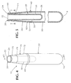
- an adapter incorporating one embodiment of the invention is generally indicated by the reference number 10.
- the adapter 10 is a generally tubular structure preferably formed of plastic, such as clear polystyrene.
- the adapter 10 includes a top end with a mouth opening 12 defined by a lip portion 14 (Fig. 7) and a bottom end with a closed hemi-spherical portion 16.
- the mouth opening 12 of the adapter 10 is sized to accommodate a relatively small tubular sample container 20, such as a Microtainer® tube.
- the sample container 20 has a mouth opening 22 (Fig. 7) defined by a lip flange 24 and a closed bottom portion 26.
- the sample container 20 also has a body portion 28 of fixed diameter that is accommodated in the mouth opening 12 of the adapter 10 to permit the lip flange 24 of the sample container 20 to rest upon the lip portion 14 of the adapter 10 as shown in Fig. 5.
- the adapter 10 has a main body portion 30 with a fixed diameter and a tapered body portion 36 that extends from the main body portion 36 to the mouth opening 12.
- the tapered body portion 36 has an outer wall 38 with a diameter that increases in a direction from the mouth opening 12 toward the main body portion 30.
- a joint 40 (Fig. 8) connects an upper end 46 of the main body portion 30 and a lower end 48 of the tapered body portion 36.
- the joint 40 includes an annular lip 42 on the main body portion 30 that projects radially outwardly from an annular recess 44 at the upper end 46 of the main body portion 30.
- the joint 40 also includes an internal annular recess 50 (Fig. 8) formed at the lower end 48 of the tapered body portion 36.
- the annular recess 50 defines an annular ledge surface 60.
- An annular lip portion 54 spaced slightly below the annular ledge 60 projects radially inwardly from the annular recess 50.
- the annular lip portion 54 includes a generally horizontal upper surface 56 and an upwardly inclined lower surface 58.
- the annular lip portion 42 on the main body portion 30 and the annular lip portion 54 on the tapered body portion 36 are sized such that the lip portion 42 is movable against the inclined lower surface 56 of the lip portion 54 with slight interference to bypass the lip portion 54 and become locked in position between the horizontal upper surface 56 and the ledge 60 of the annular recess 50 (Fig. 5).
- the joint 40 connecting the tapered body portion 36 and the main body portion 30 is an inseparable snap fit joint.
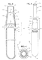
- the tapered body portion 36 preferably has two distinct tapered sections 70 and 72 (Fig. 8), with the tapered section 70 having a lesser amount of slope than the tapered section 72.
- Three equally spaced projections 74 (Fig. 8) are formed on an inner surface 76 of the tapered body portion 36 to project inwardly a predetermined amount from the inner surface 76.
- the projections 74 are preferably formed at a junction 78 between the tapered sections 70 and 72.
- the projections 74 are sized to make slight contact with the body portion 26 of the sample container 20 when the sample container 20 is positioned in the adapter 10 as shown in Fig. 5.
- the sample container 20 when inserted in the adapter 10, is gently detented therein by engagement of the projections 74 against the body portion 26 of the sample container 20.
- the force of the projections 74 against the body portion 26 of the sample container 20 is easily overcome to ensure that the lip flange 24 of the sample container 20 can rest upon the lip portion 14 of the adapter 10.
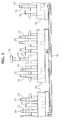
- a sample container 20 containing serum 80 that is to be subjected to sample analysis is supported in the adapter 10 as shown in Fig. 9.
- the adapter 10 is supported in a sample rack 82 (Figs. 1 and 9) of the type shown in U.S. Des. Patent 421,130.
- the rack 82 is adapted to be automatically transported in a sample analysis system along a known transport device 84 (Fig. 3).
- the rack 82 can hold a plurality of adapters 10, with each adapter holding a sample container 20 with serum 80.
- the serum 80 in each sample container 20 is usually taken from a different test subject or individual.
- the sample rack 82 can also hold standard size test tubes 90 containing reagents, diluents, or other materials generally indicated by the reference number 92 that are used at different locations in the sample analysis system and are transported to such locations with the sample rack 82.
- a predetermined amount of serum is aspirated (not shown) for each test in a battery of tests that are to be performed.
- a measurement of liquid level 110 (Fig. 9) is made before and after each aspiration of serum sample 80 to confirm that a requisite amount of sample is aspirated and also to determine the amount of serum 80 that remains in the sample container 20 after each aspiration.
- the liquid level measurement is performed using a known ultrasound detector 100 that is positioned over the transport device 84 that transports the sample racks 82.
- the ultrasound detector 100 is provided with a series of input parameters.
- the lip flange 24 (Fig. 9) of the sample container 20 is always at a fixed height "L” from a selected reference level.
- the lip flange 24 is thus always at a fixed distance "M” from the ultrasound detector 100 (Fig. 9).
- the liquid level 110 of the serum 80 in the sample container 20 is always below the level of the lip flange 24.
- the liquid level 110 is thus always at a distance (N) from the ultrasound detector 100 that is greater than the distance (M) between the detector 100 and the lip flange 24 of the sample container 20.
- the ultrasound detector 100 emits an ultrasonic wave directed, for example, at an adapter 10 that passes directly below the detector 100.
- an ultrasonic wave 102 hits the horizontal surface of the lip flange 24 an echo 104 is produced and reflected back to the ultrasound detector 100.
- the ultrasound detector 100 can determine the distance of the echo producing surface (the lip flange 24) from the ultrasound detector 100 based on the duration of time between emission of the ultrasonic wave and reception of the echo 104.
- an echo 104 from the lip flange 24 of the sample container 20 will always correspond to the distance M between the lip flange 24 of the sample container 24 and the detector 100.
- the ultrasound detector 100 When the ultrasound detector 100 produces a wave 108 (Fig. 9) that reaches the liquid level 110 in the sample container 20 an echo 112 is reflected back to the detector 100.
- the echo 112 corresponds to the distance "N" between the liquid level 110 and the sound detector 100. Since the distance “N” differs from and is greater than the distance “M” the sound detector will recognize the distance "N” as representing liquid level.
- the echo 112 corresponding to the distance "N” will always be within a known range of liquid levels.
- the sound detector 100 can reliably interpret the echo 112 as corresponding to the distance "N" which represents liquid level.
- any ultrasonic waves from the ultrasound detector 100 that reach the tapered surface 38 of the tapered body portion 36 will reflect away from the sound detector 100.
- the sound detector 100 will not receive an echo from sound waves that hit the tapered surface 38. Therefore the tapered surface 38 of the adapter 10 is essentially invisible to the ultrasound detector 100.
- the adapter 10 with the sample tube 20 presents only two surfaces to the detector 100 that produce a detectable echo, namely the lip flange surface 24 of the sample container 20 and the liquid level surface 110 within the sample container 20. Consequently the sound detector 100 can easily determine which of the two echoes 104 and 112 represent liquid level 110 and which echo does not represent liquid level, because the lip flange echo 104 is always constant and of lesser duration than the liquid level echo 112.
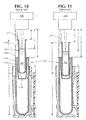
- the known sample tube support system 130 includes a sample container 20, such as a Microtainer® tube, supported in an Easi-nest® holder 132 which in turn is supported in a Vacutainer® tube 134.
- the Easi-nest® holder 132 includes a tapered inner surface 138 that bears against the body portion 26 of the sample container 20, when the sample container 20 is accommodated in the Easi-nest® holder 132.
- the height of Vacutainer® tubes 34 are substantially uniform.
- the Easi-nest® holder 132 is of substantially uniform size and shape and dimension but the inside tapered surface 138 can deviate from a norm due to manufacturing tolerances.
- the sample tube container 20 is of substantially uniform dimensions. However, the amount by which sample container 20 is recessed into the Easi-nest® holder 132 can vary significantly (compare H and H' in Figs. 10 and 11) due to tolerances of the tapered surface 138 and inconsistencies in the manual force used to push the sample tube container 20 into the Easi-nest® holder 132.
- the distance K (Figs. 10 and 11) between lip flange 140 of the Easi-nest® holder 132 and the detector 100 is substantially constant due to the uniform height of the Vacutainer® tube 134 and the uniform thickness of the lip flange 140 which rests on the mouth portion of the Vacutainer® tube 134.
- the height H of the sample tube 20 from a reference level in Fig. 10 differs from the reference level height H' of the sample tube 20 in Fig. 11 to illustrate that there is no consistency in the amount by which the sample tube 20 is pushed into the Easi-nest® holder 132.
- the distance I between the sample tube lip flange 24 and the detector 100 in Fig. 10 is less than the corresponding distance I' in Fig. 11. Consequently similar liquid levels 110 in Figs. 10 and 11 can have different distances J and J' (Figs. 10 and 11) from the sound detector 100.
- the echoes will not be of the same duration because the lip flange 24 in Fig. 10 is at a closer distance (I) to the sound detector 100 than the lip flange 24 in Fig. 11 which is at a greater distance I'.
- the sound detector 100 will also receive an echo from the liquid level surface 110 of the serum 80 in Figs. 10 and 11. As serum 80 is depleted from the sample container 20 the liquid level 110 will approach the level of the lip flange 140 of the Easi-nest® holder 132. Thus there can be confusion between an echo from the lip flange 140 of the Easi-nest® holder 132 and an echo from the liquid level 110.
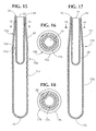
- a sample tube adapter incorporating another embodiment of the invention is generally indicated by the reference number 150 in Fig. 12.
- the sample tube adapter 150 includes a main body portion 152 and a tapered body portion 154. An upper end of the main body portion 152 and a lower end of the tapered body portion 154 include complementary shaped step portions 156 and 158. An ultrasonic welding ridge 160 is provided at one of the step portions such as the step portion 158. The main body portion 152 and the tapered body portion 154 of the sample tube adapter 150 are connected by ultrasonic welding of the step portions 156 and 158 in a known manner.
- the sample tube adapter 150 is otherwise structurally similar to the sample tube adapter 10 and supports a sample container 20 in the same manner as the sample tube adapter 10.
- sample tube adapter 170 is generally indicated by the reference number 170 in Fig. 17.
- the sample tube adapter 170 is a one piece structure that includes a bottom opening 172, a tapered body portion 174 and a main body portion 176.
- the adapter 170 is otherwise similar in structure to the adapter 10 or the adapter 150 and supports a sample container 20 in the same manner as the sample tube adapter 10.
- Some advantages of the invention evident from the foregoing description include a sample tube adapter that supports a sample container at a constant known elevation.
- the adapter and sample container reflect back to an ultrasound detector only one echo from a structural surface, namely the lip flange of the sample container and only one echo from the liquid level in the sample container that is supported by the adapter.
- the ultrasound detector can reliably distinguish liquid level from the lip flange since the echo from the liquid level is always of longer duration than the echo from the lip flange.
- the adapter has a tapered surface that deflects any ultrasound waves that hit the tapered surface away from the sound detector so that the sound detector does not detect any echoes from the tapered surface portion of the adapter. No other surface portions of the adapter reflect echoes back to the ultrasound detector. The adapter is thus invisible to the ultrasound detector. Still another advantage of the invention is that the adapter will always support the sample container at a consistent known height. Another advantage of the adapter is that it directly supports the sample container and eliminates the need for any intermediate support device between the sample container and the adapter. A further advantage is that the adapter provides a simple and novel method for liquid level sensing, eliminates guess work and confusion and is thus more reliable than known prior art methods for sensing liquid level in a sample container.
Landscapes
- Chemical & Material Sciences (AREA)
- Chemical Kinetics & Catalysis (AREA)
- Health & Medical Sciences (AREA)
- Analytical Chemistry (AREA)
- Physics & Mathematics (AREA)
- Life Sciences & Earth Sciences (AREA)
- Clinical Laboratory Science (AREA)
- Biochemistry (AREA)
- General Health & Medical Sciences (AREA)
- General Physics & Mathematics (AREA)
- Immunology (AREA)
- Pathology (AREA)
- Measurement Of Levels Of Liquids Or Fluent Solid Materials (AREA)
- Automatic Analysis And Handling Materials Therefor (AREA)
Applications Claiming Priority (2)
| Application Number | Priority Date | Filing Date | Title |
|---|---|---|---|
| US798700 | 2001-03-02 | ||
| US09/798,700 US20020121139A1 (en) | 2001-03-02 | 2001-03-02 | Adapter for holding a sample container to facilitate sensing of liquid level in the sample container |
Publications (2)
| Publication Number | Publication Date |
|---|---|
| EP1237003A2 true EP1237003A2 (de) | 2002-09-04 |
| EP1237003A3 EP1237003A3 (de) | 2004-03-24 |
Family
ID=25174057
Family Applications (1)
| Application Number | Title | Priority Date | Filing Date |
|---|---|---|---|
| EP02003179A Withdrawn EP1237003A3 (de) | 2001-03-02 | 2002-02-18 | Adapter zum Halten eines Probenbehälters zur Erleichterung der Flüssigkeitsstandmessung im Probenbehälter |
Country Status (3)
| Country | Link |
|---|---|
| US (2) | US20020121139A1 (de) |
| EP (1) | EP1237003A3 (de) |
| JP (1) | JP2002323503A (de) |
Cited By (4)
| Publication number | Priority date | Publication date | Assignee | Title |
|---|---|---|---|---|
| WO2007039524A3 (en) * | 2005-09-26 | 2007-08-23 | Qiagen Gmbh | Apparatus for processing biological material |
| DE102009004043A1 (de) * | 2009-01-08 | 2010-07-15 | Leica Biosystems Nussloch Gmbh | Vorrichtung zur Behandlung von Präparaten und Verfahren zum Ermitteln des Füllstandes von Reagenzbehältern |
| EP2818863A4 (de) * | 2012-02-24 | 2015-03-04 | Atsushi Tanabe | Gefässbodenabdeckung und gefäss |
| EP2856175B1 (de) * | 2012-06-05 | 2019-02-13 | Inpeco Holding Ltd | Schnittstellenbildungsvorrichtung zwischen einem laborautomationssystem und einer plattform zur handhabung von verbrauchsartikeln und flüssigkeiten in der molekularbiologie |
Families Citing this family (36)
| Publication number | Priority date | Publication date | Assignee | Title |
|---|---|---|---|---|
| US6878346B2 (en) * | 2002-05-17 | 2005-04-12 | Bayer Corporation | Serum transfer cup |
| DE602004008759T2 (de) * | 2004-07-06 | 2008-06-12 | Roche Diagnostics Gmbh | Ständersystem mit Adapter |
| US7604985B2 (en) * | 2004-11-10 | 2009-10-20 | Becton, Dickinson And Company | System and method for determining fill volume in a container |
| WO2006065850A1 (en) | 2004-12-16 | 2006-06-22 | Louis M. Gerson Co., Inc. | Liquid supply cup and liner assembly for spray guns |
| US7272975B2 (en) * | 2005-02-11 | 2007-09-25 | Bayer Healthcare Llc | Ultrasonic beam shaping device |
| US7513152B2 (en) * | 2005-03-04 | 2009-04-07 | Vega Grieshaber Kg | Container arrangement with a level sensor, and a level sensor for a container arrangement |
| US7421895B1 (en) | 2005-04-21 | 2008-09-09 | Caldwell Joseph W | Fluid level measuring system |
| USD531736S1 (en) * | 2005-05-04 | 2006-11-07 | Abbott Laboratories | Reagent carrier for use in an automated analyzer |
| USD533947S1 (en) * | 2005-05-04 | 2006-12-19 | Abbott Laboratories | Reagent carrier for use in an automated analyzer |
| USD532524S1 (en) * | 2005-05-04 | 2006-11-21 | Abbott Laboratories | Reagent carrier for use in an automated analyzer |
| USD534280S1 (en) * | 2005-05-04 | 2006-12-26 | Abbott Laboratories | Reagent carrier for use in an automated analyzer |
| US7472593B2 (en) * | 2005-12-01 | 2009-01-06 | Cytyc Corporation | Fluid level regulator |
| US7542870B2 (en) * | 2006-02-28 | 2009-06-02 | Ssi Technologies, Inc. | Immersed fuel level sensor |
| US7487688B2 (en) | 2006-03-20 | 2009-02-10 | Hyclone Laboratories, Inc. | Sampling ports and related container systems |
| US11040360B2 (en) | 2006-06-20 | 2021-06-22 | Saint-Gobain Abrasives, Inc. | Liquid supply assembly |
| EP2564937B1 (de) | 2006-06-20 | 2017-04-12 | Saint-Gobain Abrasives, Inc. | Flüssigkeitszufuhranordnung |
| JP4897402B2 (ja) * | 2006-09-06 | 2012-03-14 | 株式会社日立ハイテクノロジーズ | 検体容器用アダプタ、及び検体容器用ラック |
| MX2009005635A (es) * | 2006-11-28 | 2009-07-31 | Rubicon Res Pty Ltd | Dispositivo ultrasonico de deteccion de nivel con seccion ensanchada de distorsion reducida. |
| US8703492B2 (en) | 2007-04-06 | 2014-04-22 | Qiagen Gaithersburg, Inc. | Open platform hybrid manual-automated sample processing system |
| US8357538B2 (en) * | 2007-04-06 | 2013-01-22 | Qiagen Gaithersburg, Inc. | Automated assay and system |
| BE1018828A3 (nl) * | 2009-07-16 | 2011-09-06 | Praet Peter Van | Intelligent rek voor specimen buisjes en werkwijze om de buisjes in het rek te laden. |
| US9953141B2 (en) | 2009-11-18 | 2018-04-24 | Becton, Dickinson And Company | Laboratory central control unit method and system |
| US8765476B2 (en) * | 2009-12-22 | 2014-07-01 | Biocare Medical, Llc | Methods and systems for efficient automatic slide staining in immunohistochemistry sample processing |
| WO2012048154A1 (en) | 2010-10-06 | 2012-04-12 | Biocare Medical, Llc | Methods and systems for efficient processing of biological samples |
| US9945763B1 (en) | 2011-02-18 | 2018-04-17 | Biocare Medical, Llc | Methods and systems for immunohistochemistry heat retrieval of biological samples |
| WO2012154621A2 (en) * | 2011-05-06 | 2012-11-15 | Saint-Gobain Abrasives, Inc. | Paint cup assembly with an extended ring |
| US9586220B2 (en) | 2011-06-30 | 2017-03-07 | Saint-Gobain Abrasives, Inc. | Paint cup assembly |
| US10882064B2 (en) | 2011-12-30 | 2021-01-05 | Saint-Gobain Abrasives, Inc./Saint-Gobain Abrasifs | Convertible paint cup assembly with air inlet valve |
| US20130199298A1 (en) * | 2012-02-03 | 2013-08-08 | Microsonic Systems Inc. | Apparatus for automation of fluid sample processing using ultrasonic waves |
| WO2015054305A1 (en) * | 2013-10-09 | 2015-04-16 | University Of Utah Research Foundation | Sample tube adapters and methods of use thereof |
| US20150108076A1 (en) * | 2013-10-21 | 2015-04-23 | Health Diagnostic Laboratory, Inc. | Test tube rack insert device |
| CA2951696A1 (en) * | 2014-06-13 | 2015-12-17 | Theranos, Inc. | Devices and methods for use with a sample container |
| WO2016143513A1 (ja) * | 2015-03-10 | 2016-09-15 | 富士フイルム株式会社 | 測定方法及び測定装置及びプログラム |
| JP6395694B2 (ja) * | 2015-03-10 | 2018-09-26 | 富士フイルム株式会社 | 測定方法及び測定装置及びプログラム |
| US11007526B2 (en) * | 2018-07-06 | 2021-05-18 | Qorvo Us, Inc. | Capless sample well port for a cartridge |
| JP7832593B2 (ja) * | 2022-04-25 | 2026-03-18 | 株式会社島津製作所 | 液採取装置 |
Citations (1)
| Publication number | Priority date | Publication date | Assignee | Title |
|---|---|---|---|---|
| EP0979998A2 (de) * | 1998-07-14 | 2000-02-16 | Bayer Corporation | Dynamische, nichtinvasive Detektion der Merkmale von Analytikbehältern mittels Ultraschall |
Family Cites Families (102)
| Publication number | Priority date | Publication date | Assignee | Title |
|---|---|---|---|---|
| US486762A (en) * | 1892-11-22 | Measuring-vessel | ||
| US978892A (en) * | 1910-12-20 | Friedrich Oltmann Janssen | Cover for nursing-bottles. | |
| US1441092A (en) * | 1922-07-31 | 1923-01-02 | Elmore S Hoyt | Container |
| US1486450A (en) * | 1922-11-29 | 1924-03-11 | John W Peterman | Thermos-bottle closure |
| US1957677A (en) * | 1932-03-12 | 1934-05-08 | Waterman L E Co | Liquid container and housing |
| US2101310A (en) * | 1937-06-12 | 1937-12-07 | Thomas F Callaghan | Applicator for tinting hair |
| US2279075A (en) * | 1940-09-26 | 1942-04-07 | Ralph B Street | Holder for test tubes and the like |
| US2325224A (en) * | 1940-10-21 | 1943-07-27 | Frankfort Distilleries Inc | Botile holder |
| US2458737A (en) * | 1947-02-26 | 1949-01-11 | Mortimer B Salkowitz | Shockproof bottle container |
| US2591990A (en) * | 1948-10-09 | 1952-04-08 | George P Wisdom | Beverage carbonating device |
| US2677373A (en) * | 1952-05-19 | 1954-05-04 | P M Ind Inc | Plastic injection device |
| US2711099A (en) * | 1952-12-05 | 1955-06-21 | Walk Time Inc | Precipitation gauge |
| US3017050A (en) * | 1955-01-10 | 1962-01-16 | Sr Courtland H Barr | Blood sample collection apparatus |
| US2878994A (en) * | 1956-05-22 | 1959-03-24 | Owens Illinois Glass Co | Centrifuge tube and method of centrifuging |
| US2988333A (en) * | 1959-06-15 | 1961-06-13 | Frank J Mesic | Flask support |
| US3081029A (en) * | 1959-06-19 | 1963-03-12 | Copolymer Rubber & Chem Corp | Improved centrifuge tube |
| US3163544A (en) * | 1962-03-06 | 1964-12-29 | Emery I Valyi | Container |
| US3204835A (en) * | 1962-12-04 | 1965-09-07 | American Can Co | Tube structure |
| US3185351A (en) * | 1963-03-20 | 1965-05-25 | Union Carbide Corp | Aerosol cap construction |
| US3266718A (en) * | 1964-04-16 | 1966-08-16 | Beckman Instruments Inc | Sample vessel for centrifuge apparatus |
| US3475130A (en) * | 1965-07-08 | 1969-10-28 | Warner Lambert Pharmaceutical | Sample transfer apparatus |
| US3379315A (en) * | 1966-04-07 | 1968-04-23 | Maryland Plastics Inc | Test tube rack |
| US3424218A (en) * | 1966-12-07 | 1969-01-28 | Garrett Corp | Medical material container |
| US3518164A (en) * | 1967-04-11 | 1970-06-30 | B D Lab Inc | Diagnostic sputum collection system |
| GB1177047A (en) * | 1967-09-25 | 1970-01-07 | Sobrefina Sa | Improvements in and relating to Containers |
| US3570555A (en) * | 1968-11-12 | 1971-03-16 | Warren E Gilson | Fraction collector |
| US3604566A (en) * | 1969-05-01 | 1971-09-14 | Douglas J Rem | Test tube holder |
| US3655090A (en) * | 1970-06-25 | 1972-04-11 | Chicago Bridge & Iron Co | Vessel and closure with interlocking shear ring joint |
| US3625485A (en) * | 1970-09-25 | 1971-12-07 | Shapiro Justin J | Test tube rocker and rotator |
| GB1279226A (en) * | 1970-10-07 | 1972-06-28 | Vychodoslovenske Pivovary A So | Storage of beverages |
| US3727782A (en) * | 1970-12-28 | 1973-04-17 | Mansanto Co | Package for holding pressurized fluent materials |
| US3748909A (en) * | 1971-03-10 | 1973-07-31 | M Kuo | Pippette |
| US3807955A (en) * | 1971-04-15 | 1974-04-30 | Becton Dickinson Co | Serum/plasma isolator cup |
| DE2124530C3 (de) * | 1971-05-18 | 1978-04-27 | Siemens Ag, 1000 Berlin Und 8000 Muenchen | Einrichtung zum Verschließen schadhafter Wärmetauseherrohre |
| US3744665A (en) * | 1971-06-14 | 1973-07-10 | V Spoto | Combination vial and test tube rack |
| DE2221101C3 (de) * | 1972-04-28 | 1975-05-15 | Wolf-Geraete Gmbh, 5240 Betzdorf | Flaschenartiger Mischbehälter |
| DE2236528A1 (de) * | 1972-07-21 | 1974-01-31 | Dichter Hans Joachim | Glasbehaelter mit verschlusstopfen |
| US3942717A (en) * | 1973-02-09 | 1976-03-09 | Robison William O | Specimen container |
| JPS5652994Y2 (de) * | 1973-04-23 | 1981-12-10 | ||
| US3835580A (en) * | 1973-07-26 | 1974-09-17 | Tarrson Co | Bottle sand toy |
| US3918920A (en) * | 1974-01-07 | 1975-11-11 | Beckman Instruments Inc | Holder for sample containers of different sizes |
| US3918435A (en) * | 1974-01-24 | 1975-11-11 | Miles Lab | Transport swab tube |
| US3913564A (en) * | 1974-04-24 | 1975-10-21 | Richard C Freshley | Anaerobic specimen collecting and transporting device |
| NL179870C (nl) * | 1974-08-16 | 1986-12-01 | Sarstedt Kunststoff | Vat voor het afnemen van bloed met een capillair mondstuk. |
| CH590760A5 (de) * | 1975-01-03 | 1977-08-31 | Rausing Anders Ruben | |
| US4210418A (en) * | 1976-08-30 | 1980-07-01 | Mallinckrodt, Inc. | Container for immunochemical and enzymatical determinations or procedures |
| US4064760A (en) * | 1976-12-15 | 1977-12-27 | Ipco Hospital Supply Corporation | Sterile urine collection device |
| FI56750C (fi) * | 1978-02-27 | 1980-03-10 | Reijo Vihko | Rekationskaerl foer engaongsbruk vid immunologiskt bestaemning |
| US4301963A (en) * | 1978-06-05 | 1981-11-24 | Beckman Instruments, Inc. | Integral one piece centrifuge tube |
| US4221004A (en) * | 1978-08-03 | 1980-09-02 | Robertshaw Controls Company | Adjustable ultrasonic level measurement device |
| US4305559A (en) * | 1979-10-15 | 1981-12-15 | Hexcel Corporation | Support for curved surfaces |
| DD204629A1 (de) * | 1981-07-06 | 1983-12-07 | Baudisch Hans Dieter | Reduziereinsatz fuer gefaesstraeger fuer laborzentrifugen zur aufnahme von probengefaessen |
| US4437497A (en) * | 1981-09-23 | 1984-03-20 | Enander Frederick A | Ultrasonic control of filling a container |
| GB2137526B (en) * | 1983-03-26 | 1987-10-07 | James Alexander Baxter | Vial sleeve |
| US4510769A (en) * | 1984-04-05 | 1985-04-16 | Mcclellan Jr Robert D | Thermally insulating device for a beverage-containing bottle |
| US4573571A (en) * | 1984-10-05 | 1986-03-04 | Leem Tae Y | Pencil case |
| US4552278A (en) * | 1984-10-30 | 1985-11-12 | E. I. Du Pont De Nemours And Company | Crimpable capping assembly for a centrifuge tube |
| DE3525464A1 (de) * | 1985-07-17 | 1987-01-29 | Messer Griesheim Gmbh | Doppelwandiger isolierter behaelter fuer die speicherung tiefsiedender verfluessigter gase |
| US4625574A (en) * | 1985-08-26 | 1986-12-02 | Robbins Robert J | Liquid sampling method and means |
| US4690670A (en) * | 1986-01-10 | 1987-09-01 | Nielsen Steven T | Centrifuge tube having reusable seal |
| FR2609880A1 (fr) | 1987-01-22 | 1988-07-29 | Gibert Francis | Appareil de conditionnement d'un materiau fluide, notamment de vin en bouteille |
| US5374121A (en) * | 1987-05-21 | 1994-12-20 | Draenert; Klaus | Mixing apparatus with mixing rod supporting lid |
| US4944924A (en) | 1987-06-11 | 1990-07-31 | Technicon Instruments Corporation | Test tube holder |
| USD307869S (en) * | 1987-11-18 | 1990-05-15 | Miskinis Robert J | Laboratory flask holder |
| US4990129A (en) * | 1988-08-16 | 1991-02-05 | Nielsen Steven T | Swinging bucket ultracentrifuge rotor, sample tube and adapter |
| US5060823A (en) * | 1988-09-15 | 1991-10-29 | Brandeis University | Sterile transfer system |
| US5127541A (en) * | 1988-11-17 | 1992-07-07 | Koichi Wakatake | Automatic medical sampling device |
| US4932543A (en) * | 1989-01-03 | 1990-06-12 | Don Martus | Chambered bottle cap |
| US5036989A (en) * | 1989-06-22 | 1991-08-06 | Carilli Brian D | Test tube support system |
| EP0414644A3 (en) * | 1989-08-25 | 1991-08-28 | Greiner Vibrograf Ag | Chain fashioned holding device having tubes for holding a tubular vessel each |
| US4960217A (en) * | 1989-09-19 | 1990-10-02 | Teng Hsieh Yih | Balloon-type bottle sealer |
| US4989738A (en) * | 1989-10-13 | 1991-02-05 | General Electric Company | Plastic bottle with reinforced concave bottom |
| US5076456A (en) * | 1990-02-20 | 1991-12-31 | Steel Tank Institute, Inc. | Containment sump with stackable extensions |
| US5038958A (en) * | 1990-03-02 | 1991-08-13 | Norfolk Scientific, Inc. | Vented microscale centrifuge tube |
| US5137693A (en) | 1990-07-30 | 1992-08-11 | Miles Inc. | Spring biased test tube holder |
| US5316146A (en) * | 1991-03-06 | 1994-05-31 | Ulster Scientific, Inc. | Vial transporter |
| GB9107258D0 (en) * | 1991-04-06 | 1991-05-22 | Chromacol Ltd | Apparatus for use in analytical instruments |
| IT225782Y1 (it) * | 1991-07-03 | 1997-01-24 | San S R L | Confezione per il contenimento di prodotti tubolari quali fiale fialoi di e similari |
| AU5132993A (en) * | 1992-09-21 | 1994-04-12 | Habley Medical Technology Corporation | Device and method for containing an ampule and transferring liquid within the ampule to a container |
| DE4303501A1 (de) * | 1993-02-06 | 1994-08-11 | Hans Schwartz | Haltevorrichtung |
| JP3350163B2 (ja) * | 1993-06-25 | 2002-11-25 | 株式会社カイノス | 抽出用容器の保持移送装置 |
| US5470537A (en) * | 1993-08-25 | 1995-11-28 | National Scientific Company | Supporting stand for conical-bottom limited-volume vial |
| DE9400764U1 (de) * | 1994-01-18 | 1994-02-24 | Trw Repa Gmbh, 73553 Alfdorf | Kolbenfangsicherung für einen pyrotechnischen Kolben/Zylinder-Linearantrieb |
| US5549335A (en) * | 1994-04-06 | 1996-08-27 | Peerless Of America, Incorporated | Solderless metallurgical joint |
| US5842374A (en) * | 1994-06-02 | 1998-12-01 | Changmin Co., Ltd. | Measuring method of a wide range level and an apparatus thereof |
| SE505060C2 (sv) * | 1994-09-15 | 1997-06-16 | Lennart Silverstolpe | Anordning vid centrifug med roterbart armkors |
| US5515995A (en) * | 1994-12-15 | 1996-05-14 | Aladdin Synergetics, Inc. | Double wall beverage container having a wide base |
| US5669502A (en) * | 1995-04-17 | 1997-09-23 | Berlex Laboratories, Inc. | Vial holder |
| US5702036A (en) * | 1995-09-07 | 1997-12-30 | Precision Valve Corporation | Aerosol total release actuator having a delay in product emission |
| FI101610B1 (fi) * | 1995-11-22 | 1998-07-31 | Clids Oy | Näytetunnistin |
| US5686673A (en) * | 1996-07-15 | 1997-11-11 | Kabis; Thomas W. | Sampler |
| US5915583A (en) * | 1997-05-21 | 1999-06-29 | Abbott Laboraties | Container |
| US5924594A (en) * | 1997-09-12 | 1999-07-20 | Becton Dickinson And Company | Collection container assembly |
| US5975343A (en) * | 1997-09-12 | 1999-11-02 | Becton Dickinson And Company | Collection container assembly |
| US6043097A (en) * | 1997-12-05 | 2000-03-28 | Bayer Corporation | Reagent package |
| US6066299A (en) * | 1998-01-09 | 2000-05-23 | Q.I.S., Inc. | Limited volume insert bonded in a vial |
| FR2776629B1 (fr) * | 1998-03-24 | 2000-05-12 | Oreal | Tete pour la distribution et l'application d'un produit, notamment capillaire, et ensemble de conditionnement equipe d'une telle tete |
| US6045280A (en) * | 1998-06-23 | 2000-04-04 | Nadel Industries, Inc. | Container with integral wiper |
| US6276220B1 (en) * | 1998-07-10 | 2001-08-21 | Bradley P Varhol | Multipurpose groundwater sampler |
| US6331437B1 (en) * | 1998-07-14 | 2001-12-18 | Bayer Corporation | Automatic handler for feeding containers into and out of an analytical instrument |
| DE29906863U1 (de) * | 1999-04-16 | 1999-07-01 | Diedenhofen, Jochen E., 53501 Grafschaft | Geschenkartikel |
| US6158587A (en) * | 1999-08-06 | 2000-12-12 | Emery; Roy William | Expandable tapered sleeves |
-
2001
- 2001-03-02 US US09/798,700 patent/US20020121139A1/en not_active Abandoned
-
2002
- 2002-02-18 EP EP02003179A patent/EP1237003A3/de not_active Withdrawn
- 2002-03-01 JP JP2002055904A patent/JP2002323503A/ja not_active Withdrawn
- 2002-10-21 US US10/277,521 patent/US6598474B2/en not_active Expired - Fee Related
Patent Citations (1)
| Publication number | Priority date | Publication date | Assignee | Title |
|---|---|---|---|---|
| EP0979998A2 (de) * | 1998-07-14 | 2000-02-16 | Bayer Corporation | Dynamische, nichtinvasive Detektion der Merkmale von Analytikbehältern mittels Ultraschall |
Cited By (10)
| Publication number | Priority date | Publication date | Assignee | Title |
|---|---|---|---|---|
| WO2007039524A3 (en) * | 2005-09-26 | 2007-08-23 | Qiagen Gmbh | Apparatus for processing biological material |
| EP2295982A1 (de) * | 2005-09-26 | 2011-03-16 | QIAGEN GmbH | Vorrichtung zur Behandlung von biologischem Material |
| EP2295983A1 (de) * | 2005-09-26 | 2011-03-16 | Qiagen GmbH | Vorrichtung zur Behandlung von biologischem Material |
| US8932542B2 (en) | 2005-09-26 | 2015-01-13 | Qiagen Gmbh | Apparatus for processing biological material |
| US9901935B2 (en) | 2005-09-26 | 2018-02-27 | Qiagen Gmbh | Apparatus for processing biological material |
| DE102009004043A1 (de) * | 2009-01-08 | 2010-07-15 | Leica Biosystems Nussloch Gmbh | Vorrichtung zur Behandlung von Präparaten und Verfahren zum Ermitteln des Füllstandes von Reagenzbehältern |
| DE102009004043B4 (de) * | 2009-01-08 | 2012-03-22 | Leica Biosystems Nussloch Gmbh | Vorrichtung zur Behandlung von Präparaten und Verfahren zum Ermitteln des Füllstandes von Reagenzbehältern |
| EP2818863A4 (de) * | 2012-02-24 | 2015-03-04 | Atsushi Tanabe | Gefässbodenabdeckung und gefäss |
| US9541538B2 (en) | 2012-02-24 | 2017-01-10 | Atsushi Tanabe | Vessel bottom cover and vessel |
| EP2856175B1 (de) * | 2012-06-05 | 2019-02-13 | Inpeco Holding Ltd | Schnittstellenbildungsvorrichtung zwischen einem laborautomationssystem und einer plattform zur handhabung von verbrauchsartikeln und flüssigkeiten in der molekularbiologie |
Also Published As
| Publication number | Publication date |
|---|---|
| EP1237003A3 (de) | 2004-03-24 |
| US20030037611A1 (en) | 2003-02-27 |
| JP2002323503A (ja) | 2002-11-08 |
| US6598474B2 (en) | 2003-07-29 |
| US20020121139A1 (en) | 2002-09-05 |
Similar Documents
| Publication | Publication Date | Title |
|---|---|---|
| US6598474B2 (en) | Adapter for holding a sample container to facilitate sensing of liquid level in the sample container | |
| US4693834A (en) | Transverse flow diagnostic kit | |
| US4927545A (en) | Method and apparatus for automatic processing and analyzing of blood serum | |
| JP3032159B2 (ja) | 分析システム | |
| US6797518B1 (en) | Analysis method with sample quality measurement | |
| US5167922A (en) | Assay cartridge | |
| US6878346B2 (en) | Serum transfer cup | |
| EP1775574B1 (de) | Verfahren zur automatischen probenbestimmung | |
| US8721966B2 (en) | Chemical analyzer, method for dispensing and dilution cup | |
| US6197597B1 (en) | Solid phase immunoassay with carriers matching the shape of sample wells | |
| CN105874053A (zh) | 配有一体化的反应和检测装置的多槽试杯 | |
| GB1591225A (en) | Sampling apparatus | |
| WO1993025914A1 (en) | Liquid dispensing system | |
| EP0206561A2 (de) | Diagnostischer Apparat | |
| CA2275093A1 (en) | Dynamic noninvasive detection of analytical container features using ultrasound | |
| CN220340035U (zh) | 反应杯、抓手装置和样本分析仪 | |
| JPH051936A (ja) | 超音波液面計測装置 | |
| JPH08313535A (ja) | 試薬容器 | |
| CA1314409C (en) | Liquid level sensing device | |
| CN116148485A (zh) | 试管检测组件、样本分析仪以及样本分析系统 | |
| JP2007292718A (ja) | 多項目試験紙および検体中の被検物質の検出方法 | |
| CN217089303U (zh) | 用于全自动免疫生化分析仪的高底样品冻存管 | |
| CN219997093U (zh) | 化学发光检测反应容器、承载装置和样本分析仪 | |
| JPH08278235A (ja) | 液体吸引装置 | |
| CA1084728A (en) | Modular chemical analysis system |
Legal Events
| Date | Code | Title | Description |
|---|---|---|---|
| PUAI | Public reference made under article 153(3) epc to a published international application that has entered the european phase |
Free format text: ORIGINAL CODE: 0009012 |
|
| AK | Designated contracting states |
Kind code of ref document: A2 Designated state(s): AT BE CH CY DE DK ES FI FR GB GR IE IT LI LU MC NL PT SE TR |
|
| AX | Request for extension of the european patent |
Free format text: AL;LT;LV;MK;RO;SI |
|
| PUAL | Search report despatched |
Free format text: ORIGINAL CODE: 0009013 |
|
| AK | Designated contracting states |
Kind code of ref document: A3 Designated state(s): AT BE CH CY DE DK ES FI FR GB GR IE IT LI LU MC NL PT SE TR |
|
| AX | Request for extension of the european patent |
Extension state: AL LT LV MK RO SI |
|
| 17P | Request for examination filed |
Effective date: 20040924 |
|
| AKX | Designation fees paid |
Designated state(s): AT BE CH CY DE DK ES FI FR GB GR IE IT LI LU MC NL PT SE TR |
|
| 17Q | First examination report despatched |
Effective date: 20050323 |
|
| RTI1 | Title (correction) |
Free format text: A METHOD OF SENSING LIQUID LEVEL IN A SAMPLE CONTAINER. |
|
| GRAP | Despatch of communication of intention to grant a patent |
Free format text: ORIGINAL CODE: EPIDOSNIGR1 |
|
| GRAS | Grant fee paid |
Free format text: ORIGINAL CODE: EPIDOSNIGR3 |
|
| STAA | Information on the status of an ep patent application or granted ep patent |
Free format text: STATUS: THE APPLICATION IS DEEMED TO BE WITHDRAWN |
|
| 18D | Application deemed to be withdrawn |
Effective date: 20060503 |