EP1235046A1 - Thermal storage material using hydrate and thermal storage device therefor, and production method of the thermal storage material - Google Patents
Thermal storage material using hydrate and thermal storage device therefor, and production method of the thermal storage material Download PDFInfo
- Publication number
- EP1235046A1 EP1235046A1 EP00977893A EP00977893A EP1235046A1 EP 1235046 A1 EP1235046 A1 EP 1235046A1 EP 00977893 A EP00977893 A EP 00977893A EP 00977893 A EP00977893 A EP 00977893A EP 1235046 A1 EP1235046 A1 EP 1235046A1
- Authority
- EP
- European Patent Office
- Prior art keywords
- aqueous solution
- hydrate
- particles
- thermal storage
- cooling
- Prior art date
- Legal status (The legal status is an assumption and is not a legal conclusion. Google has not performed a legal analysis and makes no representation as to the accuracy of the status listed.)
- Granted
Links
Images


Classifications
-
- F—MECHANICAL ENGINEERING; LIGHTING; HEATING; WEAPONS; BLASTING
- F28—HEAT EXCHANGE IN GENERAL
- F28D—HEAT-EXCHANGE APPARATUS, NOT PROVIDED FOR IN ANOTHER SUBCLASS, IN WHICH THE HEAT-EXCHANGE MEDIA DO NOT COME INTO DIRECT CONTACT
- F28D20/00—Heat storage plants or apparatus in general; Regenerative heat-exchange apparatus not covered by groups F28D17/00 or F28D19/00
- F28D20/02—Heat storage plants or apparatus in general; Regenerative heat-exchange apparatus not covered by groups F28D17/00 or F28D19/00 using latent heat
-
- C—CHEMISTRY; METALLURGY
- C09—DYES; PAINTS; POLISHES; NATURAL RESINS; ADHESIVES; COMPOSITIONS NOT OTHERWISE PROVIDED FOR; APPLICATIONS OF MATERIALS NOT OTHERWISE PROVIDED FOR
- C09K—MATERIALS FOR MISCELLANEOUS APPLICATIONS, NOT PROVIDED FOR ELSEWHERE
- C09K5/00—Heat-transfer, heat-exchange or heat-storage materials, e.g. refrigerants; Materials for the production of heat or cold by chemical reactions other than by combustion
- C09K5/02—Materials undergoing a change of physical state when used
- C09K5/06—Materials undergoing a change of physical state when used the change of state being from liquid to solid or vice versa
- C09K5/066—Cooling mixtures; De-icing compositions
-
- F—MECHANICAL ENGINEERING; LIGHTING; HEATING; WEAPONS; BLASTING
- F28—HEAT EXCHANGE IN GENERAL
- F28D—HEAT-EXCHANGE APPARATUS, NOT PROVIDED FOR IN ANOTHER SUBCLASS, IN WHICH THE HEAT-EXCHANGE MEDIA DO NOT COME INTO DIRECT CONTACT
- F28D20/00—Heat storage plants or apparatus in general; Regenerative heat-exchange apparatus not covered by groups F28D17/00 or F28D19/00
- F28D20/02—Heat storage plants or apparatus in general; Regenerative heat-exchange apparatus not covered by groups F28D17/00 or F28D19/00 using latent heat
- F28D20/021—Heat storage plants or apparatus in general; Regenerative heat-exchange apparatus not covered by groups F28D17/00 or F28D19/00 using latent heat the latent heat storage material and the heat-exchanging means being enclosed in one container
-
- F—MECHANICAL ENGINEERING; LIGHTING; HEATING; WEAPONS; BLASTING
- F28—HEAT EXCHANGE IN GENERAL
- F28D—HEAT-EXCHANGE APPARATUS, NOT PROVIDED FOR IN ANOTHER SUBCLASS, IN WHICH THE HEAT-EXCHANGE MEDIA DO NOT COME INTO DIRECT CONTACT
- F28D20/00—Heat storage plants or apparatus in general; Regenerative heat-exchange apparatus not covered by groups F28D17/00 or F28D19/00
- F28D20/02—Heat storage plants or apparatus in general; Regenerative heat-exchange apparatus not covered by groups F28D17/00 or F28D19/00 using latent heat
- F28D20/023—Heat storage plants or apparatus in general; Regenerative heat-exchange apparatus not covered by groups F28D17/00 or F28D19/00 using latent heat the latent heat storage material being enclosed in granular particles or dispersed in a porous, fibrous or cellular structure
-
- F—MECHANICAL ENGINEERING; LIGHTING; HEATING; WEAPONS; BLASTING
- F28—HEAT EXCHANGE IN GENERAL
- F28F—DETAILS OF HEAT-EXCHANGE AND HEAT-TRANSFER APPARATUS, OF GENERAL APPLICATION
- F28F13/00—Arrangements for modifying heat-transfer, e.g. increasing, decreasing
- F28F13/06—Arrangements for modifying heat-transfer, e.g. increasing, decreasing by affecting the pattern of flow of the heat-exchange media
- F28F13/12—Arrangements for modifying heat-transfer, e.g. increasing, decreasing by affecting the pattern of flow of the heat-exchange media by creating turbulence, e.g. by stirring, by increasing the force of circulation
- F28F13/125—Arrangements for modifying heat-transfer, e.g. increasing, decreasing by affecting the pattern of flow of the heat-exchange media by creating turbulence, e.g. by stirring, by increasing the force of circulation by stirring
-
- Y—GENERAL TAGGING OF NEW TECHNOLOGICAL DEVELOPMENTS; GENERAL TAGGING OF CROSS-SECTIONAL TECHNOLOGIES SPANNING OVER SEVERAL SECTIONS OF THE IPC; TECHNICAL SUBJECTS COVERED BY FORMER USPC CROSS-REFERENCE ART COLLECTIONS [XRACs] AND DIGESTS
- Y02—TECHNOLOGIES OR APPLICATIONS FOR MITIGATION OR ADAPTATION AGAINST CLIMATE CHANGE
- Y02E—REDUCTION OF GREENHOUSE GAS [GHG] EMISSIONS, RELATED TO ENERGY GENERATION, TRANSMISSION OR DISTRIBUTION
- Y02E60/00—Enabling technologies; Technologies with a potential or indirect contribution to GHG emissions mitigation
- Y02E60/14—Thermal energy storage
-
- Y—GENERAL TAGGING OF NEW TECHNOLOGICAL DEVELOPMENTS; GENERAL TAGGING OF CROSS-SECTIONAL TECHNOLOGIES SPANNING OVER SEVERAL SECTIONS OF THE IPC; TECHNICAL SUBJECTS COVERED BY FORMER USPC CROSS-REFERENCE ART COLLECTIONS [XRACs] AND DIGESTS
- Y02—TECHNOLOGIES OR APPLICATIONS FOR MITIGATION OR ADAPTATION AGAINST CLIMATE CHANGE
- Y02P—CLIMATE CHANGE MITIGATION TECHNOLOGIES IN THE PRODUCTION OR PROCESSING OF GOODS
- Y02P20/00—Technologies relating to chemical industry
- Y02P20/10—Process efficiency
Definitions
- the temperature of internal thermal storage medium, or water varies with various conditions.
- the thermal storage temperature is necessary to be changed depending on the kind of refrigerating machine that cools the water in the water tank, or depending on the usage of the thermal load side that utilizes the water of the water tank as the thermal storage tank.
- the apparatus which uses ice, is known as one of the thermal storage medium apparatus in the world.
- the ice is produced during midnight time by utilizing midnight power and the like, and the cold thermal stored heat is utilized at air-conditioners during daytime.
- the ice-used thermal storage medium has an advantage of capable of storing a large amount of the cold thermal capacity owing to the latent heat of the ice.
- water requires to be cooled to a further low temperature than the solidification temperature thereof. On the contrary, the solidification temperature of the water is low. Therefore, the coefficient of performance of the refrigerating machine degrades.
- the ice and the ice slurry are difficult in handling and transporting, so the apparatus becomes complex and large.
- the quantity of the fine particles dispersed and floated in the aqueous solution 32 reduces to degrade the above-described effect of preventing supercooling.
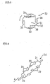
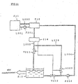
- the water 2 in the tank 1 is circulated to flow by the circulation mechanism 10, and is agitated by ascending air bubbles created by the air injected from the air-injection mechanism 20.
- the thermal storage body 30 varies their positions and moves their locations under the flow and agitation of the water 2.
- the aqueous solution 32 in the container 31 of the cooling medium body 30 is agitated to keep the fine particles 33 disperse and float in the aqueous solution 32. Consequently, the effect of preventing supercooling is sustained.
- the Seventh Embodiment has the same configuration with the Third Embodiment except for the above-given description, and the same component with that in the Third Embodiment shown in Fig. 8 has the same reference number with that in the Third Embodiment, and no further description is given here.
- the Best Mode A is not limited to the above-described Embodiments.
- the above-given Embodiments apply a container drive mechanism. If, however, the water in the tank flows owing to the heat exchange, as observed in the case of using an existing water tank for storing heat, or if the container of cooling medium body naturally changes its position or moves caused by convection flow or by varied water level, that kind of container drive mechanism is not specifically necessary.
- the concentration of the corrosion inhibitor in the TBAB hydrate slurry may be at a level to prevent corrosion.
- the concentration of 5,000 wt.ppm is sufficient.
- sodium nitrite and sodium sulfite reduce the corrosion of copper by TBAB to a level of corrosion by hot water at concentrations of max. 5,000 ppm.
- the concentration of corrosion inhibitor is 100 wt.ppm or more.
- the aqueous solution containing tetra-n-butylammonium bromide (hereinafter referred to simply as TBAB) preferably contains TBAB to a range of from 10 to 26 wt.%.
- the aqueous solution containing TBAB is preferably cooled to a temperature range of from 5°C to 8°C.
- the secondary hydrate of TBAB has larger heat capacity than that of the primary hydrate at a significance level.
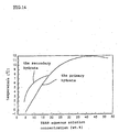
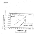
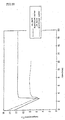
- Fig. 19 is a graph showing the heat capacity of primary hydrate and of secondary hydrate in relation with the temperatures of slurry of respective hydrates for the case of generating the primary hydrate and the secondary hydrate by cooling a 20 wt.% TBAB aqueous solution, which graph was prepared by the inventors of the present invention.
- Fig. 19 shows that the primary hydrate has about 14 kcal/kg of heat capacity at 6°C, for example, and the secondary hydrate has about 27 kcal/kg of heat capacity, which is a significant difference, (or about double the former value, in this case).
- the inventors of the present invention found that the efficient generation of the secondary hydrate is attained by cooling the TBAB aqueous solution in the initial stage of forming the TBAB hydrate slurry at cooling rates of 6 kcal/hr-kg or more.
- the TBAB aqueous solution is preferably cooled to a range of from 5°C to 8°C.
- a TBAB hydrate slurry prepared by cooling a TBAB aqueous solution containing 10 to 26 wt.% of TBAB from, for example, 12°C, which is within a temperature range of 5°C to 12°C used by general storage air conditioners, to a range of from 5°C to 8°C at the above-described cooling rate can store and transport heat ranging from 14 to 42 Mcal/m 3 corresponding to about 1 to 6 times the stored heat transport density of water. That is, very large density of heat can be stored and transferred under the condition of 26-wt.%, secondary hydrate, and 5°C.
- a line L203 connects the heat exchanger 212 and the storage tank 213.
- a hydrate identifier 214 is located in the line L203, and a valve V201 is positioned at downstream side of the hydrate identifier 214.
- the Best Mode C is described below referring to example.
- the Best Mode C is, however, not limited by these examples.
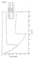
- the primary hydrate was generated after about 30 minutes, and after that, with the cooling rate of 6 kcal/hr-kg or more, the temperature of the hydrate slurry kept to around 8°C for about 120 minutes.
- the generation of primary hydrate changed to the generation of secondary hydrate. That is, when the TBAB aqueous solution is cooled at rates of 6 kcal/hr-kg or more, the secondary hydrate slurry can be produced during the initial stage of generating hydrate slurry. After completely changed to the secondary hydrate slurry, the temperature of the secondary slurry begins to reduce.
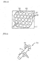
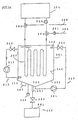
- a generation heat exchanger 307 is located in the tank 301 to generate hydrate by cooling the aqueous solution.
- the low temperature coolant is supplied and circulated from the refrigerating machine 304 to the generation heat exchanger 307 to cool the aqueous solution 303 to generate the hydrate particles.
- the hydrate slurry containing thus generated hydrate particles is held in the tank 301 to stored heat.
- the method for preventing supercooling in the case that the aqueous solution in the tank 301 is cooled to generate hydrate is described below while describing the apparatus and function thereof.
- fine particles are mixed into the aqueous solution 303, in advance. It is preferable that the fine particles have the same specific gravity with that of water or have very small size, 10 ⁇ m or less, from the viewpoint to maintain the state of dispersing and floating over the whole area of the aqueous solution 303. Nevertheless, while repeating the generation and melting of hydrate, the fine particles tend to sediment at the bottom of the tank, as described before, and tend to decrease the quantity of dispersed and floated fine particles.
- the aqueous solution ejected from the ejection nozzle 313 circulates in the tank 301.
- the circulation flow of the aqueous solution is analyzed in advance, and designed to establish the conditions that the flow speed of the aqueous solution exceeds the sedimenting speed of the fine particles even at the zone of lowest flow speed of the aqueous solution, for example, at corners of the tank 301, thus dispersing again the fine particles transferred to the bottom section of the tank 301 to prevent occurrence of precipitation of fine particles at the bottom of the tank 301.
- the fine particles are kept in their floating state owing to the circulation flow in the tank 301. Therefore, above-described granulated slag particles, which have large effect of preventing super-cooling, can be applied as the fine particles in spite of their sedimenting property, and there is no specific limitation on the material and particle size of the fine particles.
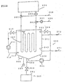
- a supersonic wave oscillation mechanism 340 is applied to the tank 301.
- the supersonic wave oscillation mechanism 340 applies supersonic waves to the aqueous solution in the tank 301 to let the fine particles disperse and float in the aqueous solution.
- An air-injection mechanism 360 is applied to the tank 301 as a mechanism for dispersing and floating the fine particles in aqueous solution.
- the air-injection mechanism 360 is structured by a high pressure air supply mechanism 361, a valve 362, an ejection nozzle 363 attached to the bottom section of the tank 301, and other components.
- the air-injection mechanism 360 supplies air from the bottom section of the tank 301 into the aqueous solution. By thus generated ascending air bubbles through the aqueous solution, the aqueous solution or hydrate slurry is agitated, and the fine particles are dispersed and floated. Since the mechanism also makes the aqueous solution surrounding the generation heat exchanger 307 flow owing to the ascending bubbles, the efficiency of the heat transfer also increases.
- the reference numbers 380, 381 designate three-way valves, and 390, 391 designate pumps.
- the Best Mode D is not limited to the above-described Embodiments.
- above-described Embodiments have various types of mechanisms for keeping the fine particles disperse and float in the aqueous solution. They are, however, not necessarily applied all of them, and only arbitrary one may be used.
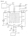
- Fig. 27 shows the configuration of a hydrate slurry producing apparatus according to the Best Mode E.
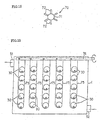
- the reference number 401 designates an storage tank holding an aqueous solution in which a hydration agent (for example, tetra-n-butylammonium bromide) is dissolved
- the reference number 405 designates a refrigerating machine for cooling a cold water as the coolant
- the reference numbers 420, 430 designate plate-type heat exchangers for conducting the heat exchange between the aqueous solution and the cold water.
- An advantage of a plate-type heat exchanger is high heat transfer performance with less compact area, because a large amount of the heat transfer area per one unit volume is available and because the heat transfer is achieved by the countercurrent mode with the narrow gap of the plate.
- the reference number 409 designates a hot water tank holding hot water for heating, where the hot water tank 409 contains a heating system.
- cutoff valves 423, 424, 433, 434 to shut the channel of the respective pipelines are attached.
- branch pipelines are located between respective cold water cutoff valves and heat exchangers.
- the branch pipelines are connected with respective hot water pipelines 410, 411 for heating via respective hot water cutoff valves 425, 426, 435, 436 to shut the flow of respective branch pipelines.
- the respective inlets and outlets of the aqueous solution pipelines of respective heat exchangers 420, 430 are provided with respective aqueous solution cutoff valves 421, 422, 431, 432 to shut the channel of the respective aqueous solution pipelines.
- the aqueous solution cutoff valves 421, 422 are closed, the cold water cutoff valves 423, 424 are closed, the hot water cutoff valves 425, 426 are opened, further the hot water pump 412 is actuated to let the hot water in the hot water tank 409 pass through the cold water passage in the heat exchanger 420, thus conducting the operation for melting hydrate to melt the hydrate adhered to the cooling surface of plates.
- the hot water referred herein may be at 12°C or higher temperature. Accordingly, hot water can use outlet hot water and drain water of absorption refrigerating machine, cooling water of a cooling tower, on return water of an air-conditioner.
- That melting operation is given successively to attain stable production of hydrate slurry.
- the first means is to apply coating on the surface of cooling side of plate, or aqueous solution side, to reduce friction factor thereof.
- the coating includes electroplating such as hard chromium coating, nickel coating, iron coating, alloy coating, electroless nickel coating using phosphorus, boron, or the like, dispersion coating such as electrocrystallization coating and electroless nickel coating, and lubricating alloy coating.
- the surface of the separation blade member 609 is covered by a surface 710 on which the nucleus particles are adhered.
- the nucleus particles adhered surface 710 is prepared by applying a mixture of fine particles, for example, of granulated slag particles, prepared by ejecting water against a blast furnace slag to finely pulverize, mixed with a binder.
- the nucleus particles adhered surface 710 is not limited to position on the surface of the separation blade member 609, and may be located at any surface where the flowing aqueous solution contact therewith.
- the reference number 511 in the figure designates an aqueous solution tank to hold the aqueous solution.
- the aqueous solution in the aqueous solution tank 511 is supplied to a charge opening 506 of the generation heat exchanger 501 by a pump 513 via a supply pipe 515 and a mixer 516.
- the hydrate slurry in the hydrate particles tank 534 is sent to the mixer 516 by a pump 535 via a pipe 536, and is fed to the charge opening 506 of the generation heat exchanger 501 along with the aqueous solution.
- the apparatus is provided with a hydrate particle generation mechanism 514.
- the hydrate particles generation mechanism 514 can be operated separately from the hydrate production apparatus containing the generation heat exchanger 501, and is able to produce hydrate slurry containing small amount of hydrate particles.
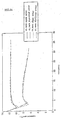
- Fig. 32 shows the case that granular particles having 100 ⁇ m or smaller size are mixed as the nucleus particles in the aqueous solution.
- the figure shows high preventive effect against supercooling, down to about 4°C for 40% concentration of aqueous solution, and to about 6°C for 19.8% concentration of aqueous solution.
- the Best Mode F is not limited to the above-given Embodiments.
- the above-given Embodiments deal with the case of using a generation heat exchanger of cooling cylinder type provided with separation blade member.
- the Best Mode F is not limited to the case, and, for example, a shell and tube generation heat exchanger may be applied.
- the nucleus particles used in the Best Mode F are not limited to those having heavy specific gravity.
- nucleus particles having almost equal specific gravity with that of the aqueous solution may be used. Those nucleus particles flow with the aqueous solution and do not sediment, so they prevent various kinds of problems caused by precipitation of the nucleus particles.
- a method for producing a hydrate-base thermal storage medium that can be generated at higher temperature than the temperature of ice is provided without using special coolant.
- the TBAB secondary hydrate that has excellent heat capacity is efficiently produced while suppressing the appearance of supercool of the primary hydrate.
Landscapes
- Engineering & Computer Science (AREA)
- Chemical & Material Sciences (AREA)
- Physics & Mathematics (AREA)
- Thermal Sciences (AREA)
- Mechanical Engineering (AREA)
- General Engineering & Computer Science (AREA)
- Chemical Kinetics & Catalysis (AREA)
- Combustion & Propulsion (AREA)
- Materials Engineering (AREA)
- Organic Chemistry (AREA)
- Dispersion Chemistry (AREA)
- Other Air-Conditioning Systems (AREA)
Abstract
Description
Claims (40)
- A thermal storage apparatus for using a hydrate thermal storage medium comprising:a storage tank for storing a cooling medium liquid;a refrigerating machine, connected with the storage tank via a pipe for cooling the cooling medium liquid, the cooling medium liquid circulating between the storage tank and the refrigerating machine;a thermal storage body immersed in the cooling medium liquid, wherein the thermal storage medium comprising,a hermetically sealed container,an aqueous solution filled in the hermetically sealed container, to generate a hydrate and;fine particles to prevent the aqueous solution from super-cooling, the fine particles being contained in the hermetically sealed container.
- The thermal storage apparatus according to claim 1, further comprising container drive means for changing position of the container and moving the container in the cooling medium liquid to disperse the fine particles in the container.
- The thermal storage apparatus according to claim 2, wherein the container drive means comprises a fluid mechanism to change position of the container or to move the container by fluidizing the cooling medium liquid in the storage tank.
- The thermal storage apparatus according to claim 2, wherein the container drive means comprises an air-injection mechanism. to change position of the container or to move the container by injecting air into the cooling medium liquid in the storage tank and by ascending air bubbles.
- The thermal storage apparatus according to claim 2,wherein the container drive means comprises a mechanical drive mechanism for mechanically changing position of the container or moving the container.
- The thermal storage apparatus according to claim 1, wherein the container of the thermal storage medium floats freely in the cooling medium liquid in the storage tank.
- The thermal storage apparatus according to claim 1, wherein the container of the thermal storage medium is supported in the storage tank in a free-rotational mode.
- The thermal storage apparatus according to claim 1, wherein the container of the storage tank provides at least one piece of blade members outside of the container, to promote changing position of the container or moving the container.
- The thermal storage apparatus according to claim 1, wherein the aqueous solution filled in the hermetically sealed container contains a guest compound, where the generation temperature of the hydrate varies in accordance with the concentration of the aqueous solution.
- The thermal storage apparatus according to claim 1, wherein the fine particles have a diameter size of 100µm or less.
- The thermal storage apparatus according to claim 1, wherein the fine particles have a diameter size of 10µm or less.
- The thermal storage apparatus according to claim 1, wherein the fine particles have a diameter size of 100µm or less, and the fine particles in the aqueous solution have a concentration of 0.1 mg/l or more.
- A hydrate thermal storage medium comprising:an aqueous solution containing a guest compound, the aqueous solution comprising;a thermal storage medium slurry containing the guest compound; and,a corrosion inhibitor at least one selected from the group consisting of sodium nitrite, sodium sulfite, sodium pyrophosphate, and benzotriazole.
- The hydrate thermal storage medium according to claim 13, wherein the contained corrosion inhibitor is 5,000 wt.ppm or less of concentration.
- The hydrate thermal storage medium according to claim 13, wherein the guest compound is one selected from the group consisting of a tetra-n-butylammonium salt, a tetra-iso-amylammonium salt, a tetra-iso-butylphosphonium salt, and a tri-iso-amylsulfonium salt.
- A method for producing a hydrate thermal storage medium comprising the steps of:(a) preparing an aqueous solution containing a guest compound; and,(b) cooling the aqueous solution to produce a hydrate slurry.
- The method according to claim 16. wherein the aqueous solution is cooled at a rate of 6 kcal/hr-kg or more.
- The method according to claim16, wherein the aqueous solution contains the guest compound at a concentration of from 10 to 26 wt.%.
- The method according to claim16, wherein the aqueous solution is cooled to a temperature range of from 5°C to 8°C.
- The method according to claim 16, wherein the guest compound is one selected from the group consisting of a tetra-n-butylammonium salt, a tetra-iso-amylammonium salt, a tetra-iso-butylphosphonium salt, or a tri-iso-amylsulfonium salt.
- A method for producing a hydrate slurry comprising the steps of:(a) preparing an aqueous solution containing a guest compound;and,(b) cooling the aqueous solution and contacting nucleus particles as nucleus of the hydrate particles with the aqueous solution to produce the hydrate particles.
- The method according to claim 21, wherein the nucleus particles comprise hydrate particles.
- The method according to claim 21, wherein the nucleus particles comprise fine particles.
- The method according to claim 21, wherein the nucleus particles have a diameter size of 300µm or less.
- The method according to claim 21, wherein the nucleus particles have a diameter size of 100µm or less.
- The method according to claim 21, wherein the nucleus particles have a diameter size of 10µm or less.
- The method according to claim 21, wherein the nucleus particles have a diameter size of 10µm or less and the nucleus particles in the aqueous solution have a concentration of 0.1 mg/l or more.
- The method according to claim 21, wherein the nucleus particles comprise fine particles having heavier specific gravity than the specific gravity of the aqueous solution, and wherein the step of contacting the nucleus particles with the aqueous solution comprises dispersing and floating the nucleus particles in the aqueous solution.
- The method according to claim 21, wherein the step of contacting the nucleus particles with the aqueous solution comprises dispersing and floating the nucleus particles precipitated in the aqueous solution.
- The method according to claim 21, wherein the specific gravity of the nucleus particles is almost equal with the specific gravity of the aqueous solution, and the nucleus particles are dispersed and floated in the aqueous solution.
- The method according to claim 21, wherein the step of contacting the nucleus particles with the aqueous solution comprises the step of agitating the aqueous solution containing the nucleus particles.
- The method according to claim 21, wherein the step of contacting the nucleus particles with the aqueous solution comprises the step of contacting the aqueous solution with members to which surface the nucleus particles adhere.
- An apparatus for producing hydrate slurry by cooling an aqueous solution containing a guest compound and by generating hydrate particles comprising:a generation heat exchanger having a heat transfer surface for cooling the aqueous solution and cooling the aqueous solution by contacting the aqueous solution with the heat transfer surface; and,a nucleus particles supply mechanism for supplying the nucleus particles as nuclei of the hydrate particles to the aqueous solution passing through the generation heat exchanger.
- The apparatus according to claim 33, wherein the nucleus particles supply mechanism comprises a supply mechanism for supplying the hydrate particles.
- The apparatus according to claim 33, wherein the nucleus particles supply mechanism comprises a hydrate particle generation mechanism capable of operation independent from the generation heat exchanger.
- The apparatus according to claim 33, wherein the nucleus particles supply mechanism comprises a storage tank holding a part of the hydrate slurry produced in the generation heat exchanger.
- The apparatus according to claim 33, wherein the nucleus particles supply mechanism comprises a nucleus particle recovery mechanism for recovering the nucleus particles precipitated in the aqueous solution and for supplying the recovered nucleus particles to the generation heat exchanger.
- An apparatus for producing a hydrate slurry by cooling an aqueous solution containing a guest compound, comprising:a generation heat exchanger having a heat transfer surface for cooling the aqueous solution and cooling the aqueous solution by the contacting the aqueous solution with the heat transfer surface; and,at least one part of a surface of members, wherein the surface contacts with the aqueous solution in the generation heat exchanger, and wherein nucleus particles as nuclei of the hydrate particles adhere to the surface.
- The apparatus according to claim 38, wherein the generation heat exchanger comprises:a cylindrical heat transfer surface,a separation blade member rotating, simultaneously with contacting and sliding on the heat transfer surface for separating the hydrate generated on the heat transfer surface, and,a surface of the separation blade member having a surface adhered by the nucleus particles.
- An apparatus for producing a hydrate slurry by cooling an aqueous solution containing a guest compound and by generating hydrate particles comprising:a generation heat exchanger having a heat transfer surface for cooling the aqueous solution and cooling the aqueous solution by contacting the aqueous solution with the heat transfer surface; and,an agitation mechanism for dispersing and floating the nucleus particles as nuclei of the hydrate particles in the aqueous solution.
Applications Claiming Priority (9)
| Application Number | Priority Date | Filing Date | Title |
|---|---|---|---|
| JP33617099 | 1999-11-26 | ||
| JP33617099A JP3956556B2 (en) | 1999-11-26 | 1999-11-26 | Method and apparatus for producing tetra n-butylammonium bromide hydrate heat storage material slurry |
| JP36117999A JP2001172617A (en) | 1999-12-20 | 1999-12-20 | Tetra n-butyl ammonium bromide hydrate heat storage material |
| JP36117999 | 1999-12-20 | ||
| JP2000246333A JP4617548B2 (en) | 2000-08-15 | 2000-08-15 | Hydrate slurry production method, hydrate slurry production apparatus and aqueous solution |
| JP2000246335 | 2000-08-15 | ||
| JP2000246335 | 2000-08-15 | ||
| JP2000246333 | 2000-08-15 | ||
| PCT/JP2000/008272 WO2001038811A1 (en) | 1999-11-26 | 2000-11-24 | Thermal storage material using hydrate and thermal storage device therefor, and production method of the thermal storage material |
Publications (3)
| Publication Number | Publication Date |
|---|---|
| EP1235046A1 true EP1235046A1 (en) | 2002-08-28 |
| EP1235046A4 EP1235046A4 (en) | 2009-03-04 |
| EP1235046B1 EP1235046B1 (en) | 2011-10-05 |
Family
ID=27480547
Family Applications (1)
| Application Number | Title | Priority Date | Filing Date |
|---|---|---|---|
| EP00977893A Expired - Lifetime EP1235046B1 (en) | 1999-11-26 | 2000-11-24 | Thermal storage material using hydrate and thermal storage device therefor, and production method of the thermal storage material |
Country Status (4)
| Country | Link |
|---|---|
| US (2) | US20020189277A1 (en) |
| EP (1) | EP1235046B1 (en) |
| KR (1) | KR100455839B1 (en) |
| WO (1) | WO2001038811A1 (en) |
Cited By (11)
| Publication number | Priority date | Publication date | Assignee | Title |
|---|---|---|---|---|
| EP1510763A4 (en) * | 2002-05-31 | 2005-11-16 | Jfe Eng Corp | DEVICE FOR PRODUCING HYDRATE BOUILLIE |
| ES2262391A1 (en) * | 2004-05-06 | 2006-11-16 | Acufrio, S.L. | Air conditioning system has heat accumulator, provided inside enclosure, which stores phase transition medium having phase change temperature lower and higher than maximum and minimum outside temperatures |
| WO2010012822A3 (en) * | 2008-08-01 | 2010-04-01 | Frank Trenkner | Latent hybrid heat accumulator |
| US7824725B2 (en) | 2007-03-30 | 2010-11-02 | The Coca-Cola Company | Methods for extending the shelf life of partially solidified flowable compositions |
| WO2011012685A3 (en) * | 2009-07-31 | 2011-07-14 | Frank Trenkner | Latent hybrid heat reservoir having improved heat transfer, and method for operating a latent hybrid heat reservoir |
| WO2014059163A1 (en) | 2012-10-10 | 2014-04-17 | Promethean Power Systems, Inc. | Thermal energy battery with enhanced heat exchange capability and modularity |
| CN104047699A (en) * | 2013-03-15 | 2014-09-17 | 株式会社东芝 | COOLING APPARATUS AND COOLING METHOD for cooling heating element |
| EP3006883A4 (en) * | 2013-07-12 | 2016-06-29 | Aisin Seiki | Chemical thermal energy storage device |
| WO2018055242A1 (en) * | 2016-09-26 | 2018-03-29 | Amvalor | Heat exchanger comprising at least one phase change material for optimising and controlling heat transfer |
| EP3330656A4 (en) * | 2015-07-31 | 2019-03-06 | Pioneer Energy (Jiangsu) Co., Ltd | HEAT STORAGE DEVICE WITH PHASE CHANGE |
| CN109442849A (en) * | 2018-11-01 | 2019-03-08 | 中科美菱低温科技股份有限公司 | A kind of storage box and its control system based on phase-change material |
Families Citing this family (23)
| Publication number | Priority date | Publication date | Assignee | Title |
|---|---|---|---|---|
| WO2001038811A1 (en) * | 1999-11-26 | 2001-05-31 | Nkk Corporation | Thermal storage material using hydrate and thermal storage device therefor, and production method of the thermal storage material |
| US20080072495A1 (en) * | 1999-12-30 | 2008-03-27 | Waycuilis John J | Hydrate formation for gas separation or transport |
| WO2007002608A2 (en) * | 2005-06-27 | 2007-01-04 | Solid Gas Technologies Llc | Clathrate hydrate modular storage, applications and utilization processes |
| KR100735178B1 (en) * | 2006-02-23 | 2007-07-03 | 엘지전자 주식회사 | Regenerative Air Conditioning Unit |
| US7812203B2 (en) * | 2006-10-30 | 2010-10-12 | Chevron U.S.A. Inc. | Process for continuous production of hydrates |
| US7964150B2 (en) * | 2006-10-30 | 2011-06-21 | Chevron U.S.A. Inc. | Apparatus for continuous production of hydrates |
| BRPI0905987A2 (en) | 2008-02-22 | 2015-06-30 | Dow Global Technologies Inc | Thermal energy storage material system, method for manufacturing a thermal energy storage material system and use of a thermal energy storage material system |
| WO2011062793A1 (en) * | 2009-11-18 | 2011-05-26 | Exxonmobil Upstream Research Company | Apparatus, system, and methods for generating a non-plugging hydrate slurry |
| US20110056219A1 (en) * | 2009-09-08 | 2011-03-10 | Industrial Idea Partners, Inc. | Utilization of Exhaust of Low Pressure Condensing Steam Turbine as Heat Input to Silica Gel-Water Working Pair Adsorption Chiller |
| US8486281B2 (en) * | 2009-10-05 | 2013-07-16 | Kesheng Feng | Nickel-chromium alloy stripper for flexible wiring boards |
| US20110239959A1 (en) * | 2010-04-05 | 2011-10-06 | Chuang Shuo-Wei | Water heat source generator device |
| US9250000B2 (en) * | 2010-07-24 | 2016-02-02 | Matthew Rosenfeld | Techniques for indirect cold temperature thermal energy storage |
| EP2645005A1 (en) * | 2012-03-28 | 2013-10-02 | VGE bvba | A heat pump system using latent heat |
| RU2592883C2 (en) | 2013-08-30 | 2016-07-27 | Общество С Ограниченной Ответственностью "Яндекс" | Cooling system, method of operating such system and backup cooling device |
| JP6337675B2 (en) * | 2014-07-29 | 2018-06-06 | 株式会社デンソー | Heat storage system |
| JP6601145B2 (en) * | 2014-11-14 | 2019-11-06 | 株式会社デンソー | Subcool release substance and method for producing the same |
| DE102016121825B4 (en) * | 2016-11-14 | 2025-07-24 | Rittal Gmbh & Co. Kg | Chiller with compression refrigerant circuit and buffer storage, a corresponding cooling arrangement and a corresponding operating procedure |
| CN108931404B (en) * | 2017-05-23 | 2021-10-22 | 中国石油化工股份有限公司 | A method for rapid synthesis of natural gas hydrate samples |
| JP6946967B2 (en) | 2017-11-22 | 2021-10-13 | 住友電装株式会社 | Terminal holder, wire harness, fixed structure |
| US10815975B1 (en) * | 2018-03-06 | 2020-10-27 | Lester Reid Hopkins | Heavy water ocean thermal energy conversion method and system |
| CN109579523B (en) * | 2018-11-29 | 2020-05-05 | 大余明发矿业有限公司 | Improved natural gas heat accumulating type lead melting furnace |
| KR102228996B1 (en) * | 2019-11-26 | 2021-03-17 | 한국과학기술연구원 | Dualpipe heat exchanger using phase change materials |
| US11598589B2 (en) * | 2020-01-15 | 2023-03-07 | Sanjay K Roy | Rotor cooling system |
Family Cites Families (100)
| Publication number | Priority date | Publication date | Assignee | Title |
|---|---|---|---|---|
| US2802344A (en) | 1953-07-08 | 1957-08-13 | Eureka Williams Corp | Electrodialysis of solutions in absorption refrigeration |
| US3309885A (en) | 1966-02-04 | 1967-03-21 | Allied Chem | Absorption refrigeration |
| US3834456A (en) | 1972-07-03 | 1974-09-10 | Dow Chemical Co | Aqueous organic heat-sink fluids |
| US3976584A (en) * | 1973-05-18 | 1976-08-24 | Board Of Control Of Michigan Technological University | Thermal energy storage material |
| US4024170A (en) | 1975-11-11 | 1977-05-17 | The University Of Alabama | Liquid clathrates |
| US4180124A (en) | 1976-10-26 | 1979-12-25 | Broad Corporation | Process and apparatus for heat exchange |
| US4217329A (en) | 1978-03-13 | 1980-08-12 | Petrolite Corporation | Sulfone containing quaternary ammonium derivatives of 1,4-thiazines |
| US4188359A (en) | 1978-03-13 | 1980-02-12 | Petrolite Corporation | Thioether containing quartenary ammonium derivatives of 1,4-thiazines |
| US4336156A (en) | 1978-08-09 | 1982-06-22 | Petrolite Corporation | Quaternary ammonium salts of α-1,4-thiazine alkanephosphonic acids |
| US4332690A (en) * | 1979-04-23 | 1982-06-01 | Mitsubishi Denki Kabushiki Kaisha | Heat storage system comprising a phase change medium and a nucleating agent |
| US4341657A (en) | 1979-04-23 | 1982-07-27 | Petrolite Corporation | Use of quaternized derivatives of polymerized pyridines and quinolines as corrosion inhibitors |
| US4285389A (en) * | 1979-12-26 | 1981-08-25 | Horton Jack F | Thermal energy storage apparatus |
| JPS5832279A (en) | 1981-08-19 | 1983-02-25 | Fujitsu Ltd | Air cleaning method in magnetic device |
| JPS5832279U (en) * | 1981-08-24 | 1983-03-02 | 株式会社クボタ | Latent heat storage device |
| JPS58168891A (en) * | 1982-03-29 | 1983-10-05 | Mitsui Eng & Shipbuild Co Ltd | Heat accumulator by inorganic salt hydrate method |
| JPS59134494A (en) * | 1983-01-20 | 1984-08-02 | Agency Of Ind Science & Technol | Heat accumulator |
| GB8310662D0 (en) | 1983-04-20 | 1983-05-25 | Allied Colloids Ltd | Exothermic reactions |
| US4498997A (en) | 1983-06-24 | 1985-02-12 | Halliburton Company | Method and composition for acidizing subterranean formations |
| US4585572A (en) | 1983-10-11 | 1986-04-29 | The Dow Chemical Company | Reversible phase change composition for storing thermal energy |
| JPS617376A (en) * | 1984-06-20 | 1986-01-14 | Matsushita Electric Ind Co Ltd | Activation method of crystal nucleation material |
| US4522658A (en) | 1984-06-21 | 1985-06-11 | Halliburton Company | Method and composition for protecting metal surfaces from oxidative environments |
| JPS61145274A (en) * | 1984-12-19 | 1986-07-02 | Mitsubishi Heavy Ind Ltd | Cold storage agent |
| US4686059A (en) | 1986-02-12 | 1987-08-11 | First Brands Corporation | Antimony tartrate corrosion inhibitive composition for coolant systems |
| US4796493A (en) * | 1986-04-21 | 1989-01-10 | Menard Richard J | Apparatus and method for unscrewing a bicycle chain sprocket |
| JPS63118546A (en) | 1986-11-05 | 1988-05-23 | Takenaka Komuten Co Ltd | Air conditioning system for building |
| JPS6488327A (en) | 1987-09-30 | 1989-04-03 | Ricoh Kk | Shape measuring method for interference wave front |
| JPH0188327U (en) * | 1987-12-03 | 1989-06-12 | ||
| US4821794A (en) | 1988-04-04 | 1989-04-18 | Thermal Energy Storage, Inc. | Clathrate thermal storage system |
| JPH0219682A (en) | 1988-07-08 | 1990-01-23 | Toshiba Corp | Fluid compressor |
| JPH0240431A (en) * | 1988-07-29 | 1990-02-09 | Hiroshi Akashi | Ice heat storage system |
| JPH02122981A (en) | 1988-11-02 | 1990-05-10 | Oji Paper Co Ltd | heat sensitive recording material |
| JPH06104380B2 (en) | 1988-11-02 | 1994-12-21 | 新王子製紙株式会社 | Thermal recording |
| JPH0796941B2 (en) | 1989-02-02 | 1995-10-18 | 三機工業株式会社 | Cold storage system |
| JPH02122980U (en) * | 1989-03-07 | 1990-10-09 | ||
| JPH02122981U (en) * | 1989-03-10 | 1990-10-09 | ||
| JP2863226B2 (en) * | 1989-12-07 | 1999-03-03 | 株式会社竹中工務店 | Ice making equipment |
| US5477917A (en) | 1990-01-09 | 1995-12-26 | The University Of Dayton | Dry powder mixes comprising phase change materials |
| US5139549A (en) * | 1991-04-05 | 1992-08-18 | Chicago Bridge & Iron Technical Services Company | Apparatus and method for cooling using aqueous ice slurry |
| US5140824A (en) * | 1991-05-28 | 1992-08-25 | Hunt Steven C | Gas hydrate thermal energy storage system |
| US5239839A (en) * | 1991-06-17 | 1993-08-31 | James Timothy W | Thermal energy storage apparatus enabling use of aqueous or corrosive thermal storage media |
| US5159971A (en) | 1991-06-27 | 1992-11-03 | Allied-Signal Inc. | Cooling medium for use in a thermal energy storage system |
| US5128051A (en) | 1991-09-30 | 1992-07-07 | Union Carbide Chemicals & Plastics Technology Corporation | Method for the control of biofouling |
| JPH05149656A (en) * | 1991-11-30 | 1993-06-15 | Toupure Kk | Portable cold storage container |
| JP3203781B2 (en) | 1992-07-23 | 2001-08-27 | 株式会社リコー | Facsimile machine |
| US5497630A (en) * | 1992-09-30 | 1996-03-12 | Thermal Electric Devices, Inc. | Method and apparatus for hydride heat pumps |
| JPH0646179U (en) * | 1992-11-10 | 1994-06-24 | 株式会社間組 | Heat storage device |
| JPH06159963A (en) * | 1992-11-27 | 1994-06-07 | Matsushita Electric Works Ltd | Heat accumulator |
| ATE149039T1 (en) | 1992-12-22 | 1997-03-15 | Allied Signal Inc | CLATHRATE-FORMING MEDIUM, ITS USE IN THERMAL ENERGY STORAGE SYSTEMS, AND PROCESSES FOR THERMAL ENERGY STORAGE AND TRANSFER |
| US5434330A (en) * | 1993-06-23 | 1995-07-18 | Hnatow; Miguel A. | Process and apparatus for separation of constituents of gases using gas hydrates |
| JPH0719682A (en) * | 1993-06-29 | 1995-01-20 | Mitsui Eng & Shipbuild Co Ltd | Method for producing ice slurry in ice heat storage device |
| US5473904A (en) * | 1993-11-12 | 1995-12-12 | New Mexico Tech Research Foundation | Method and apparatus for generating, transporting and dissociating gas hydrates |
| US5524453A (en) * | 1994-08-01 | 1996-06-11 | James; Timothy W. | Thermal energy storage apparatus for chilled water air-conditioning systems |
| US6059016A (en) * | 1994-08-11 | 2000-05-09 | Store Heat And Produce Energy, Inc. | Thermal energy storage and delivery system |
| SE9500159L (en) | 1995-01-19 | 1996-01-08 | Akzo Nobel Nv | Use of an alkoxylated alkanolamine together with an alkoxylated alcohol as a friction reducing agent |
| JPH0933185A (en) * | 1995-05-16 | 1997-02-07 | Denso Corp | Heat storage with stirring function |
| JP3114005B2 (en) * | 1995-07-12 | 2000-12-04 | 株式会社日立製作所 | Gas turbine intake cooling system and operation method thereof |
| JPH09157640A (en) * | 1995-12-08 | 1997-06-17 | Asahi Denka Kogyo Kk | Anticorrosive agent for heat storage material composition |
| JP3324392B2 (en) * | 1996-04-25 | 2002-09-17 | 三菱電機株式会社 | Heat storage material |
| US6096680A (en) | 1996-10-28 | 2000-08-01 | Albemarle Corporation | Liquid clathrate compositions |
| US6370908B1 (en) * | 1996-11-05 | 2002-04-16 | Tes Technology, Inc. | Dual evaporator refrigeration unit and thermal energy storage unit therefore |
| US6028234A (en) * | 1996-12-17 | 2000-02-22 | Mobil Oil Corporation | Process for making gas hydrates |
| US6237346B1 (en) * | 1997-04-14 | 2001-05-29 | Nkk Corporation | Method for transporting cold latent heat and system therefor |
| JP3309760B2 (en) | 1997-01-20 | 2002-07-29 | 日本鋼管株式会社 | Cold transport medium, cold transport method, cold transport system and method for changing melting point of semi-clathrate hydrate |
| JP4043551B2 (en) | 1997-05-23 | 2008-02-06 | 栗田工業株式会社 | Scale inhibitor and scale prevention method |
| US6268317B1 (en) | 1997-10-30 | 2001-07-31 | Matsushita Electric Industrial Co., Ltd. | Working fluid for refrigerating cycle equipment and the refrigerating cycle equipment using the same |
| JP3641362B2 (en) | 1998-03-18 | 2005-04-20 | Jfeエンジニアリング株式会社 | Cold storage method using cold clathrate, cold storage system, and cold storage agent |
| US20020014329A1 (en) | 1998-06-29 | 2002-02-07 | Peter Carr | Integrated heating and cooling system for a vehicle |
| US6082118A (en) | 1998-07-07 | 2000-07-04 | Mobil Oil Corporation | Storage and transport of gas hydrates as a slurry suspenion under metastable conditions |
| US20040069454A1 (en) | 1998-11-02 | 2004-04-15 | Bonsignore Patrick V. | Composition for enhancing thermal conductivity of a heat transfer medium and method of use thereof |
| US6432320B1 (en) | 1998-11-02 | 2002-08-13 | Patrick Bonsignore | Refrigerant and heat transfer fluid additive |
| US6158499A (en) | 1998-12-23 | 2000-12-12 | Fafco, Inc. | Method and apparatus for thermal energy storage |
| JP3555481B2 (en) * | 1999-02-15 | 2004-08-18 | Jfeエンジニアリング株式会社 | Method and apparatus for producing hydrate slurry |
| CA2300521C (en) * | 1999-03-15 | 2004-11-30 | Takahiro Kimura | Production method for hydrate and device for proceeding the same |
| US6510698B2 (en) * | 1999-05-20 | 2003-01-28 | Mitsubishi Denki Kabushiki Kaisha | Refrigeration system, and method of updating and operating the same |
| US6393861B1 (en) * | 1999-09-17 | 2002-05-28 | Robert Levenduski | Thermal storage apparatus and method for air conditioning system |
| US6374907B1 (en) | 1999-10-08 | 2002-04-23 | 3M Innovative Properties Company | Hydrofluoroether as a heat-transfer fluid |
| US6303080B1 (en) | 1999-10-08 | 2001-10-16 | 3M Innovative Properties Company | Hydrofluoroethers as heat-transfer fluids in low temperature processes requiring sterilization |
| DE19948480A1 (en) * | 1999-10-08 | 2001-04-12 | Bsh Bosch Siemens Hausgeraete | Heat exchangers such as evaporators, condensers or the like |
| WO2001038811A1 (en) | 1999-11-26 | 2001-05-31 | Nkk Corporation | Thermal storage material using hydrate and thermal storage device therefor, and production method of the thermal storage material |
| US6350928B1 (en) | 1999-12-30 | 2002-02-26 | Marathon Oil Company | Production of a gas hydrate slurry using a fluidized bed heat exchanger |
| US6703534B2 (en) | 1999-12-30 | 2004-03-09 | Marathon Oil Company | Transport of a wet gas through a subsea pipeline |
| US7511180B2 (en) | 1999-12-30 | 2009-03-31 | Marathon Oil Company | Stabilizing petroleum liquids for storage or transport |
| JP3475901B2 (en) | 2000-03-31 | 2003-12-10 | Jfeエンジニアリング株式会社 | Hydrate slurry generator with different hydration numbers |
| US6528025B1 (en) | 2000-06-26 | 2003-03-04 | Roche Vitamins Inc. | Process of manufacturing equipment for preparing acetals and ketals |
| DE10031558A1 (en) | 2000-06-28 | 2002-01-10 | Clariant Gmbh | Process for conditioning organic pigments |
| US6408633B1 (en) * | 2000-08-08 | 2002-06-25 | Instatherm Company | Interfacing of thermal storage systems with air conditioning units |
| US6481213B2 (en) * | 2000-10-13 | 2002-11-19 | Instatherm Company | Personal thermal comfort system using thermal storage |
| US20030151030A1 (en) | 2000-11-22 | 2003-08-14 | Gurin Michael H. | Enhanced conductivity nanocomposites and method of use thereof |
| US6994156B2 (en) * | 2001-04-20 | 2006-02-07 | Coolsmart Llc | Air-conditioning system with thermal storage |
| JP4089187B2 (en) * | 2001-08-31 | 2008-05-28 | 株式会社日立製作所 | Thermoelectric supply system |
| JP5019683B2 (en) | 2001-08-31 | 2012-09-05 | 三菱重工業株式会社 | Gas hydrate slurry dewatering apparatus and method |
| FR2830318B1 (en) | 2001-10-03 | 2004-03-26 | Centre Nat Rech Scient | INSTALLATION AND METHOD FOR THE PRODUCTION OF COLD OR HEAT BY A SORPTION SYSTEM |
| EP1510763B1 (en) * | 2002-05-31 | 2012-02-01 | JFE Engineering Corporation | Apparatus for producing hydrate slurry |
| US6858157B2 (en) | 2003-04-17 | 2005-02-22 | Vnaderbilt University | Compositions with nano-particle size diamond powder and methods of using same for transferring heat between a heat source and a heat sink |
| US6681593B1 (en) * | 2003-05-28 | 2004-01-27 | Robert W. Gundlach | Thermal energy storage system |
| US7032398B2 (en) * | 2004-02-27 | 2006-04-25 | Toromont Industries Ltd. | Energy management system, method, and apparatus |
| MXPA06013529A (en) * | 2004-05-25 | 2007-08-21 | Ice Energy Inc | Refrigerant-based thermal energy storage and cooling system with enhanced heat exchange capability. |
| US7371907B2 (en) * | 2004-07-07 | 2008-05-13 | Los Alamos National Security, Llc | Ice method for production of hydrogen clathrate hydrates |
| JP2006052934A (en) | 2004-07-12 | 2006-02-23 | Sanyo Electric Co Ltd | Heat exchange apparatus and refrigerating machine |
| US7421846B2 (en) * | 2004-08-18 | 2008-09-09 | Ice Energy, Inc. | Thermal energy storage and cooling system with gravity fed secondary refrigerant isolation |
-
2000
- 2000-11-24 WO PCT/JP2000/008272 patent/WO2001038811A1/en not_active Ceased
- 2000-11-24 EP EP00977893A patent/EP1235046B1/en not_active Expired - Lifetime
- 2000-11-24 KR KR10-2002-7006018A patent/KR100455839B1/en not_active Expired - Fee Related
-
2002
- 2002-05-23 US US10/155,356 patent/US20020189277A1/en not_active Abandoned
-
2004
- 2004-01-05 US US10/754,049 patent/US7246506B2/en not_active Expired - Fee Related
Cited By (17)
| Publication number | Priority date | Publication date | Assignee | Title |
|---|---|---|---|---|
| US7541009B2 (en) | 2002-05-31 | 2009-06-02 | Jfe Engineering Corporation | Apparatus for producing hydrate slurry |
| EP1510763A4 (en) * | 2002-05-31 | 2005-11-16 | Jfe Eng Corp | DEVICE FOR PRODUCING HYDRATE BOUILLIE |
| ES2262391A1 (en) * | 2004-05-06 | 2006-11-16 | Acufrio, S.L. | Air conditioning system has heat accumulator, provided inside enclosure, which stores phase transition medium having phase change temperature lower and higher than maximum and minimum outside temperatures |
| ES2262391B1 (en) * | 2004-05-06 | 2007-11-01 | Acufrio, S.L. | AIR-CONDITIONING SYSTEM. |
| US7824725B2 (en) | 2007-03-30 | 2010-11-02 | The Coca-Cola Company | Methods for extending the shelf life of partially solidified flowable compositions |
| WO2010012822A3 (en) * | 2008-08-01 | 2010-04-01 | Frank Trenkner | Latent hybrid heat accumulator |
| WO2011012685A3 (en) * | 2009-07-31 | 2011-07-14 | Frank Trenkner | Latent hybrid heat reservoir having improved heat transfer, and method for operating a latent hybrid heat reservoir |
| US9557120B2 (en) | 2012-10-10 | 2017-01-31 | Promethean Power Systems, Inc. | Thermal energy battery with enhanced heat exchange capability and modularity |
| WO2014059163A1 (en) | 2012-10-10 | 2014-04-17 | Promethean Power Systems, Inc. | Thermal energy battery with enhanced heat exchange capability and modularity |
| US10088243B2 (en) | 2012-10-10 | 2018-10-02 | Promethean Power Systems, Inc. | Thermal energy battery with enhanced heat exchange capability and modularity |
| EP2906894A4 (en) * | 2012-10-10 | 2016-08-03 | Promethean Power Systems Inc | THERMAL BATTERY WITH IMPROVED CAPACITY AND MODULARITY OF HEAT EXCHANGE |
| CN104047699A (en) * | 2013-03-15 | 2014-09-17 | 株式会社东芝 | COOLING APPARATUS AND COOLING METHOD for cooling heating element |
| EP3006883A4 (en) * | 2013-07-12 | 2016-06-29 | Aisin Seiki | Chemical thermal energy storage device |
| EP3330656A4 (en) * | 2015-07-31 | 2019-03-06 | Pioneer Energy (Jiangsu) Co., Ltd | HEAT STORAGE DEVICE WITH PHASE CHANGE |
| WO2018055242A1 (en) * | 2016-09-26 | 2018-03-29 | Amvalor | Heat exchanger comprising at least one phase change material for optimising and controlling heat transfer |
| CN109442849A (en) * | 2018-11-01 | 2019-03-08 | 中科美菱低温科技股份有限公司 | A kind of storage box and its control system based on phase-change material |
| CN109442849B (en) * | 2018-11-01 | 2020-11-13 | 中科美菱低温科技股份有限公司 | Preservation box based on phase-change material and control system thereof |
Also Published As
| Publication number | Publication date |
|---|---|
| US7246506B2 (en) | 2007-07-24 |
| KR20020065515A (en) | 2002-08-13 |
| KR100455839B1 (en) | 2004-11-06 |
| US20050016200A1 (en) | 2005-01-27 |
| US20020189277A1 (en) | 2002-12-19 |
| WO2001038811A1 (en) | 2001-05-31 |
| EP1235046B1 (en) | 2011-10-05 |
| EP1235046A4 (en) | 2009-03-04 |
Similar Documents
| Publication | Publication Date | Title |
|---|---|---|
| US7246506B2 (en) | Thermal storage medium using a hydrate and apparatus thereof, and method for producing the thermal storage medium | |
| JP3555481B2 (en) | Method and apparatus for producing hydrate slurry | |
| JP2001010990A (en) | Methane hydrate production apparatus and production method | |
| Yan et al. | Experimental study of dynamic melting process in an ice-on-coil storage system | |
| US7537639B2 (en) | Method of cooling molten metal during fractional crystallisation | |
| JPH06185762A (en) | Cooling or heating method | |
| JP2000205775A (en) | Method for producing clathrate hydrate slurry | |
| JP2850264B2 (en) | Storage and heat dissipation method | |
| JP4665820B2 (en) | Method for promoting solidification and melting of heat storage material and heat storage device | |
| JP4617548B2 (en) | Hydrate slurry production method, hydrate slurry production apparatus and aqueous solution | |
| JP4853851B2 (en) | High-temperature cooling device using latent heat transport inorganic hydrate slurry | |
| JP2003268361A (en) | Method of producing ice in water slurry having reducing effect on flow resistance, transporting method and transporting system for the same | |
| JP2002130746A (en) | Thermal storage device and renewal method thereof | |
| JPH0914705A (en) | Fluid transfer device | |
| JP4385506B2 (en) | Hydrate heat storage method and apparatus | |
| JPH05215369A (en) | Cooling or heating method using latent heat | |
| JP2009275977A (en) | Cooling tower system | |
| JP2001355980A5 (en) | ||
| JPH0370928A (en) | Ice heat accumulator | |
| JPH10160208A (en) | Dynamic type ice making device and cool storage utilization system using the same | |
| JP2002162068A (en) | Thermal storage unit, thermal storage tank, and thermal storage system | |
| CN120252272A (en) | Refrigeration cycle system with phase change | |
| JPH02110229A (en) | ice heat storage device | |
| JPH10325657A (en) | Ice storage device | |
| JPH07204491A (en) | Method for producing microcapsule dispersion for heat transfer |
Legal Events
| Date | Code | Title | Description |
|---|---|---|---|
| PUAI | Public reference made under article 153(3) epc to a published international application that has entered the european phase |
Free format text: ORIGINAL CODE: 0009012 |
|
| 17P | Request for examination filed |
Effective date: 20020624 |
|
| AK | Designated contracting states |
Kind code of ref document: A1 Designated state(s): AT BE CH CY DE DK ES FI FR GB GR IE IT LI LU MC NL PT SE TR |
|
| RAP1 | Party data changed (applicant data changed or rights of an application transferred) |
Owner name: JFEENGINEERING CORPORATION |
|
| RBV | Designated contracting states (corrected) |
Designated state(s): AT BE CH DE FR GB LI |
|
| A4 | Supplementary search report drawn up and despatched |
Effective date: 20090203 |
|
| 17Q | First examination report despatched |
Effective date: 20090922 |
|
| GRAP | Despatch of communication of intention to grant a patent |
Free format text: ORIGINAL CODE: EPIDOSNIGR1 |
|
| RBV | Designated contracting states (corrected) |
Designated state(s): DE FR GB |
|
| RAP1 | Party data changed (applicant data changed or rights of an application transferred) |
Owner name: JFE ENGINEERING CORPORATION |
|
| RIN1 | Information on inventor provided before grant (corrected) |
Inventor name: TAKAO, SHINGO,C/O JFE ENGINEERING CORPORATION Inventor name: MATSUMOTO, SHIGENORI,C/O JFE ENGINEERING CORPORATI Inventor name: OGOSHI, HIDEMASA,C/O JFE ENGINEERING CORPORATION Inventor name: FUKUSHIMA, SHINICHIRO,C/OJFE ENGINEERING CORPORATI |
|
| GRAS | Grant fee paid |
Free format text: ORIGINAL CODE: EPIDOSNIGR3 |
|
| GRAA | (expected) grant |
Free format text: ORIGINAL CODE: 0009210 |
|
| AK | Designated contracting states |
Kind code of ref document: B1 Designated state(s): DE FR GB |
|
| REG | Reference to a national code |
Ref country code: GB Ref legal event code: FG4D |
|
| REG | Reference to a national code |
Ref country code: DE Ref legal event code: R096 Ref document number: 60046526 Country of ref document: DE Effective date: 20111229 |
|
| PLBE | No opposition filed within time limit |
Free format text: ORIGINAL CODE: 0009261 |
|
| STAA | Information on the status of an ep patent application or granted ep patent |
Free format text: STATUS: NO OPPOSITION FILED WITHIN TIME LIMIT |
|
| 26N | No opposition filed |
Effective date: 20120706 |
|
| REG | Reference to a national code |
Ref country code: DE Ref legal event code: R097 Ref document number: 60046526 Country of ref document: DE Effective date: 20120706 |
|
| PGFP | Annual fee paid to national office [announced via postgrant information from national office to epo] |
Ref country code: GB Payment date: 20141119 Year of fee payment: 15 Ref country code: FR Payment date: 20141110 Year of fee payment: 15 Ref country code: DE Payment date: 20141118 Year of fee payment: 15 |
|
| REG | Reference to a national code |
Ref country code: DE Ref legal event code: R119 Ref document number: 60046526 Country of ref document: DE |
|
| GBPC | Gb: european patent ceased through non-payment of renewal fee |
Effective date: 20151124 |
|
| REG | Reference to a national code |
Ref country code: FR Ref legal event code: ST Effective date: 20160729 |
|
| PG25 | Lapsed in a contracting state [announced via postgrant information from national office to epo] |
Ref country code: DE Free format text: LAPSE BECAUSE OF NON-PAYMENT OF DUE FEES Effective date: 20160601 Ref country code: GB Free format text: LAPSE BECAUSE OF NON-PAYMENT OF DUE FEES Effective date: 20151124 |
|
| PG25 | Lapsed in a contracting state [announced via postgrant information from national office to epo] |
Ref country code: FR Free format text: LAPSE BECAUSE OF NON-PAYMENT OF DUE FEES Effective date: 20151130 |