EP1234971B1 - Procédé de commande pour un système d'injection à rampe d'alimentation commune en cas de defaillance de capteur de pression - Google Patents
Procédé de commande pour un système d'injection à rampe d'alimentation commune en cas de defaillance de capteur de pression Download PDFInfo
- Publication number
- EP1234971B1 EP1234971B1 EP02251067A EP02251067A EP1234971B1 EP 1234971 B1 EP1234971 B1 EP 1234971B1 EP 02251067 A EP02251067 A EP 02251067A EP 02251067 A EP02251067 A EP 02251067A EP 1234971 B1 EP1234971 B1 EP 1234971B1
- Authority
- EP
- European Patent Office
- Prior art keywords
- fuel
- pressure
- metering valve
- injector
- control
- Prior art date
- Legal status (The legal status is an assumption and is not a legal conclusion. Google has not performed a legal analysis and makes no representation as to the accuracy of the status listed.)
- Expired - Lifetime
Links
- 239000000446 fuel Substances 0.000 title claims abstract description 174
- 238000000034 method Methods 0.000 title claims abstract description 27
- 238000002347 injection Methods 0.000 title claims description 54
- 239000007924 injection Substances 0.000 title claims description 54
- 238000012544 monitoring process Methods 0.000 claims abstract description 5
- 230000001419 dependent effect Effects 0.000 claims description 2
- 230000001276 controlling effect Effects 0.000 description 9
- 230000001105 regulatory effect Effects 0.000 description 9
- 238000010586 diagram Methods 0.000 description 4
- 238000002485 combustion reaction Methods 0.000 description 3
- 238000005086 pumping Methods 0.000 description 2
- 230000005856 abnormality Effects 0.000 description 1
- 238000001514 detection method Methods 0.000 description 1
Images

Classifications
-
- F—MECHANICAL ENGINEERING; LIGHTING; HEATING; WEAPONS; BLASTING
- F02—COMBUSTION ENGINES; HOT-GAS OR COMBUSTION-PRODUCT ENGINE PLANTS
- F02D—CONTROLLING COMBUSTION ENGINES
- F02D41/00—Electrical control of supply of combustible mixture or its constituents
- F02D41/30—Controlling fuel injection
- F02D41/38—Controlling fuel injection of the high pressure type
- F02D41/3809—Common rail control systems
- F02D41/3836—Controlling the fuel pressure
- F02D41/3845—Controlling the fuel pressure by controlling the flow into the common rail, e.g. the amount of fuel pumped
-
- F—MECHANICAL ENGINEERING; LIGHTING; HEATING; WEAPONS; BLASTING
- F02—COMBUSTION ENGINES; HOT-GAS OR COMBUSTION-PRODUCT ENGINE PLANTS
- F02D—CONTROLLING COMBUSTION ENGINES
- F02D31/00—Use of speed-sensing governors to control combustion engines, not otherwise provided for
- F02D31/001—Electric control of rotation speed
-
- F—MECHANICAL ENGINEERING; LIGHTING; HEATING; WEAPONS; BLASTING
- F02—COMBUSTION ENGINES; HOT-GAS OR COMBUSTION-PRODUCT ENGINE PLANTS
- F02D—CONTROLLING COMBUSTION ENGINES
- F02D41/00—Electrical control of supply of combustible mixture or its constituents
- F02D41/22—Safety or indicating devices for abnormal conditions
- F02D41/222—Safety or indicating devices for abnormal conditions relating to the failure of sensors or parameter detection devices
-
- F—MECHANICAL ENGINEERING; LIGHTING; HEATING; WEAPONS; BLASTING
- F02—COMBUSTION ENGINES; HOT-GAS OR COMBUSTION-PRODUCT ENGINE PLANTS
- F02M—SUPPLYING COMBUSTION ENGINES IN GENERAL WITH COMBUSTIBLE MIXTURES OR CONSTITUENTS THEREOF
- F02M63/00—Other fuel-injection apparatus having pertinent characteristics not provided for in groups F02M39/00 - F02M57/00 or F02M67/00; Details, component parts, or accessories of fuel-injection apparatus, not provided for in, or of interest apart from, the apparatus of groups F02M39/00 - F02M61/00 or F02M67/00; Combination of fuel pump with other devices, e.g. lubricating oil pump
- F02M63/02—Fuel-injection apparatus having several injectors fed by a common pumping element, or having several pumping elements feeding a common injector; Fuel-injection apparatus having provisions for cutting-out pumps, pumping elements, or injectors; Fuel-injection apparatus having provisions for variably interconnecting pumping elements and injectors alternatively
- F02M63/0225—Fuel-injection apparatus having a common rail feeding several injectors ; Means for varying pressure in common rails; Pumps feeding common rails
-
- F—MECHANICAL ENGINEERING; LIGHTING; HEATING; WEAPONS; BLASTING
- F02—COMBUSTION ENGINES; HOT-GAS OR COMBUSTION-PRODUCT ENGINE PLANTS
- F02D—CONTROLLING COMBUSTION ENGINES
- F02D41/00—Electrical control of supply of combustible mixture or its constituents
- F02D41/22—Safety or indicating devices for abnormal conditions
- F02D41/222—Safety or indicating devices for abnormal conditions relating to the failure of sensors or parameter detection devices
- F02D2041/223—Diagnosis of fuel pressure sensors
-
- F—MECHANICAL ENGINEERING; LIGHTING; HEATING; WEAPONS; BLASTING
- F02—COMBUSTION ENGINES; HOT-GAS OR COMBUSTION-PRODUCT ENGINE PLANTS
- F02M—SUPPLYING COMBUSTION ENGINES IN GENERAL WITH COMBUSTIBLE MIXTURES OR CONSTITUENTS THEREOF
- F02M41/00—Fuel-injection apparatus with two or more injectors fed from a common pressure-source sequentially by means of a distributor
- F02M41/08—Fuel-injection apparatus with two or more injectors fed from a common pressure-source sequentially by means of a distributor the distributor and pumping elements being combined
- F02M41/14—Fuel-injection apparatus with two or more injectors fed from a common pressure-source sequentially by means of a distributor the distributor and pumping elements being combined rotary distributor supporting pump pistons
- F02M2041/1438—Arrangements or details pertaining to the devices classified in F02M41/14 and subgroups
- F02M2041/1444—Feed-pumps; Arrangements or pressure regulation therefor
-
- F—MECHANICAL ENGINEERING; LIGHTING; HEATING; WEAPONS; BLASTING
- F02—COMBUSTION ENGINES; HOT-GAS OR COMBUSTION-PRODUCT ENGINE PLANTS
- F02M—SUPPLYING COMBUSTION ENGINES IN GENERAL WITH COMBUSTIBLE MIXTURES OR CONSTITUENTS THEREOF
- F02M41/00—Fuel-injection apparatus with two or more injectors fed from a common pressure-source sequentially by means of a distributor
- F02M41/08—Fuel-injection apparatus with two or more injectors fed from a common pressure-source sequentially by means of a distributor the distributor and pumping elements being combined
- F02M41/14—Fuel-injection apparatus with two or more injectors fed from a common pressure-source sequentially by means of a distributor the distributor and pumping elements being combined rotary distributor supporting pump pistons
- F02M2041/1438—Arrangements or details pertaining to the devices classified in F02M41/14 and subgroups
- F02M2041/145—Throttle valves for metering fuel to the pumping chamber
-
- F—MECHANICAL ENGINEERING; LIGHTING; HEATING; WEAPONS; BLASTING
- F02—COMBUSTION ENGINES; HOT-GAS OR COMBUSTION-PRODUCT ENGINE PLANTS
- F02M—SUPPLYING COMBUSTION ENGINES IN GENERAL WITH COMBUSTIBLE MIXTURES OR CONSTITUENTS THEREOF
- F02M41/00—Fuel-injection apparatus with two or more injectors fed from a common pressure-source sequentially by means of a distributor
- F02M41/08—Fuel-injection apparatus with two or more injectors fed from a common pressure-source sequentially by means of a distributor the distributor and pumping elements being combined
- F02M41/14—Fuel-injection apparatus with two or more injectors fed from a common pressure-source sequentially by means of a distributor the distributor and pumping elements being combined rotary distributor supporting pump pistons
- F02M2041/1438—Arrangements or details pertaining to the devices classified in F02M41/14 and subgroups
- F02M2041/1483—Variably timed valves controlling fuel passages, e.g. sleeve-valves mounted on the rotor
-
- F—MECHANICAL ENGINEERING; LIGHTING; HEATING; WEAPONS; BLASTING
- F02—COMBUSTION ENGINES; HOT-GAS OR COMBUSTION-PRODUCT ENGINE PLANTS
- F02M—SUPPLYING COMBUSTION ENGINES IN GENERAL WITH COMBUSTIBLE MIXTURES OR CONSTITUENTS THEREOF
- F02M41/00—Fuel-injection apparatus with two or more injectors fed from a common pressure-source sequentially by means of a distributor
- F02M41/08—Fuel-injection apparatus with two or more injectors fed from a common pressure-source sequentially by means of a distributor the distributor and pumping elements being combined
- F02M41/14—Fuel-injection apparatus with two or more injectors fed from a common pressure-source sequentially by means of a distributor the distributor and pumping elements being combined rotary distributor supporting pump pistons
- F02M2041/1438—Arrangements or details pertaining to the devices classified in F02M41/14 and subgroups
- F02M2041/1488—Electric actuation of valves or other parts
-
- F—MECHANICAL ENGINEERING; LIGHTING; HEATING; WEAPONS; BLASTING
- F02—COMBUSTION ENGINES; HOT-GAS OR COMBUSTION-PRODUCT ENGINE PLANTS
- F02M—SUPPLYING COMBUSTION ENGINES IN GENERAL WITH COMBUSTIBLE MIXTURES OR CONSTITUENTS THEREOF
- F02M41/00—Fuel-injection apparatus with two or more injectors fed from a common pressure-source sequentially by means of a distributor
- F02M41/08—Fuel-injection apparatus with two or more injectors fed from a common pressure-source sequentially by means of a distributor the distributor and pumping elements being combined
- F02M41/14—Fuel-injection apparatus with two or more injectors fed from a common pressure-source sequentially by means of a distributor the distributor and pumping elements being combined rotary distributor supporting pump pistons
- F02M41/1405—Fuel-injection apparatus with two or more injectors fed from a common pressure-source sequentially by means of a distributor the distributor and pumping elements being combined rotary distributor supporting pump pistons pistons being disposed radially with respect to rotation axis
- F02M41/1411—Fuel-injection apparatus with two or more injectors fed from a common pressure-source sequentially by means of a distributor the distributor and pumping elements being combined rotary distributor supporting pump pistons pistons being disposed radially with respect to rotation axis characterised by means for varying fuel delivery or injection timing
- F02M41/1427—Arrangements for metering fuel admitted to pumping chambers, e.g. by shuttles or by throttle-valves
Definitions
- the invention relates to a method of controlling a fuel system for use in delivering fuel to an internal combustion engine.
- the invention relates to a method of controlling the fuel system so as to provide a limp-home capability in the event that a fault condition occurs within the system.
- the invention also relates to a fuel system arranged to provide a limp-home capability in the event of such a fault.
- a common rail system typically includes a source of fuel in the form of a common rail which is charged with fuel at high pressure by means of a high pressure fuel pump.
- the common rail delivers fuel to a plurality of injectors, each one being arranged to inject fuel into an associated engine cylinder.
- the common rail is provided with a rail pressure sensor providing an output signal indicative of the pressure of fuel within the common rail and, hence, the pressure of fuel delivered to the injectors.
- the quantity of fuel to be injected during an injection event is calculated by means of an appropriately programmed control unit in response to a driver demand signal and other operating conditions of the engine, for example speed and temperature.
- the quantity of fuel delivered during an injection event depends upon both the pressure of fuel within the common rail and the duration for which an injection occurs.
- the supply of current to the pressure regulating valve is varied by the control unit in response to the pressure sensor output signal so as to ensure the required rail pressure is maintained.
- US 5937826 describes a control system for an internal combustion engine in which a low pressure pump supplies a pressure regulated supply of fuel to a high pressure pump.
- High pressure fuel from the pump is delivered to an accumulator under the control of ON/OFF valves, each of which controls the fuel flow from a respective pumping cylinder of the pump.
- the high pressure pump is controlled in response to a requested fuelling signal, an engine speed signal and a pressure output from a pressure sensor.
- the system operates closed loop such that fuel pressure within the accumulator is controlled by switching the high pressure pump valves between ON and OFF (open and closed) states in response to the requested fuelling signal, the engine speed signal and the pressure output.
- the system operates open loop in response to a predicted pump command signal based on fuel command and engine speed.
- An appropriate pump command value is determined, either directly or by interpolation from a look up table, for various fuel command values and engine speed values.
- EP 0 569 227 describes a fuel injection system providing limp home functionality by interrupting fuel supply in case of abnormality in the control system.
- the present invention provides a method of controlling the operation of a common rail fuel system including a common rail charged with pressurised fuel by means of a high pressure fuel pump, the common rail being arranged to deliver fuel to at least one fuel injector, the system further including a metering valve arrangement arranged to control the flow of fuel delivered to the high pressure fuel pump and a pressure sensor arranged to provide an output signal indicative of the pressure of fuel delivered to the injector, the method comprising controlling the rate of flow of fuel delivered from the common rail to the injector by supplying the metering valve arrangement with a control current; measuring the speed of the engine; monitoring the status of the pressure sensor so as to determine whether a fault condition has occurred; and in the event that a fault condition has occurred, varying the control current supplied to the metering valve arrangement in response to the measured engine speed so as to maintain engine operation at a substantially constant speed.
- the invention provides the advantage that, even in the event of failure of the pressure sensor, operation of the engine can be maintained to provide a limp-home capability. This enables the driver of the vehicle to move the vehicle to a safe location or to a service centre.
- the system operates closed loop by feeding the measured engine speed to determine a control current for the metering valve arrangement.
- the method includes the step of moving a valve member of the metering valve arrangement through a range of operating positions so as to vary the rate of flow of fuel to the high pressure pump and, hence, the pressure within the common rail.
- the metering valve member is conveniently arranged to vary the extent to which an orifice in a flow path between a transfer pump and the high pressure pump is opened.
- the method comprises the further step of:
- the pressure control means and the injection control means form part of a control unit programmed with an appropriate control algorithm.
- the method may include the step of generating a predetermined injection current to be supplied to the injector arrangement in the event that a fault condition occurs so as to set a duration for which an injection of fuel occurs, such that the quantity of fuel delivered by the injector depends only upon the control current supplied to the metering valve arrangement.
- the injection control means provide a predetermined injection current to the injector to control the duration for which an injection of fuel occurs.
- the speed of the engine is measured and, if the measured speed is less than a predetermined, demanded speed, the control current supplied to the metering valve arrangement is increased so as to increase the rate of flow of fuel from the high pressure pump to the injector.
- the pressure of fuel supplied to the injector is increased, thereby causing an increase in the quantity of fuel injected by the injector and, hence, an increase in engine speed.
- the control current supplied to the metering valve arrangement is reduced so as to reduce the rate of flow of fuel to the injector, thereby reducing the pressure of fuel supplied to the injector.
- the quantity of fuel delivered by the injector is therefore reduced and, hence, the engine speed is reduced. In this way, the engine speed can be maintained at a substantially constant speed, sufficient to enable the vehicle to be driven to an appropriate location for service or repair.
- the predetermined injection current sets a predetermined duration for which an injection of fuel occurs, and is derived from a demanded engine speed which is typically greater than the idling speed of the engine.
- the metering valve arrangement may be arranged such that an increase in the control current supplied to the metering valve arrangement causes a decrease in the rate of flow of fuel supplied to the high pressure fuel pump, and hence a decrease in the pressure of fuel supplied to the injectors.
- a fuel system for an engine includes at least one fuel injector; a common rail charged with high pressure fuel by means of a high pressure fuel pump, wherein the common rail is arranged to deliver fuel to the injector; a pressure sensor arranged to provide an output signal indicative of the pressure of fuel delivered to the injector and a metering valve arrangement including a valve member which is movable through a range of operating positions to vary the rate of flow of fuel to the source and, hence, the pressure of fuel to be delivered to the injector.
- the fuel system further includes control means for controlling a current supplied to the metering valve arrangement; means for measuring the speed of the engine and a monitor for monitoring the status of the pressure sensor so as to determine whether a fault condition has occurred within the sensor.
- the control means is arranged to vary the control current supplied to the metering valve arrangement in response to the measured engine speed so as to maintain engine operation at a substantially constant engine speed in the event that a fault condition is detected by the monitor.
- the system may include a pressure control means for supplying the current to the metering valve arrangement and an injection control means for supplying an injection current to the injector so as to control the duration for which an injection of fuel occurs.
- the pressure control means and the injection control means form part of a control unit programmed with an appropriate control algorithm.
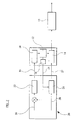
- the common rail fuel system in the accompanying drawings includes a pump arrangement comprising a transfer pump 1 and a high pressure pump 10, wherein the transfer pump 1 is arranged to receive low pressure fuel through an inlet 2 and delivers fuel at transfer pressure to the high pressure fuel pump 10 through an inlet metering valve arrangement 4.
- the transfer pump 1 and the high pressure pump 10 are driven together by the engine at a drive speed of approximately 50% of engine speed.
- a transfer pressure regulator 3 is connected across the inlet and outlet of the transfer pump 1 to regulate the pressure of fuel supplied to the inlet metering valve arrangement 4.
- the pump arrangement is provided with a return flow path to low pressure through an outlet 5 in a conventional manner.
- the high pressure pump is arranged to supply fuel at high pressure to a common rail 12.
- the common rail 12 delivers fuel to a plurality of fuel injectors 14 forming part of an injector arrangement, each of the fuel injectors 14 being arranged to deliver fuel to a cylinder or other combustion space of an associated engine (not shown).
- Each of the injectors 14 has a backleak connection to permit leakage fuel to flow through a return flow path through the outlet 5 to low pressure.
- the metering valve arrangement 4 is operable in response to a supply current signal 16 generated by an engine control unit (ECU) 20 to control the rate of flow of fuel to the high pressure pump 10.
- the metering valve arrangement 4 takes the form of a proportional valve, including a valve member 4 a which is movable through a range of operating positions under the influence of an actuator.
- the actuator is supplied with the current signal 16 to vary the extent to which an orifice of the arrangement 4 located in the flow path between the transfer pump 1 and the high pressure pump 10 is opened by the valve member 4. The extent to which the orifice is opened determines the rate of flow of fuel between the transfer pump 1 and the high pressure pump 10.
- the rate of flow of fuel to the high pressure pump 10 is relatively low, whereas if the metering valve member 4 a is moved to a more open position, the rate of flow of fuel to the high pressure pump 10 is higher. Therefore, by varying the current 16 supplied to the actuator, the position of the metering valve member 4 a can be varied, and the rate of flow of fuel delivered to the high pressure pump 10, and hence the rate of flow of fuel delivered to the common rail 12, can be controlled.
- the rate of flow of fuel supplied to the common rail 12 determines the pressure of fuel within the common rail 12 (referred to as "rail pressure") and, hence, the pressure of fuel supplied to the injectors 14.
- the common rail 12 is provided with a pressure sensor 18 which generates a rail pressure output signal 19 indicative of the pressure of fuel within the common rail 12 and, hence, the pressure of fuel delivered to the injectors 14.
- the flow of fuel delivered by the high pressure pump 10 to the rail 12 is dependent upon rail pressure, the speed of operation of the high pressure pump 10 and the rate of flow of fuel between the transfer pump 1 and the high pressure pump 10 through the metering valve arrangement 4.
- the rate of flow of fuel through the orifice of the metering valve arrangement 4 is proportional to the square root of the pressure difference across the inlet and outlet sides of the arrangement. This pressure difference depends upon fuel pressure in the rail, and also on quantity of fuel delivered to the rail 12 during the previous pumping cycle, and it is not therefore possible to predict the rate of flow of fuel delivered by the high pressure pump 10 to the rail 12 from the position of the metering valve arrangement 4, nor by measuring the current supplied to the metering valve arrangement 4. In order to control the rate of flow of fuel from the high pressure pump 10, it is therefore important to feed back the rail pressure output signal 19 to a pressure control scheme of the engine control unit 20.
- FIG 2 is a schematic diagram of the fuel system in Figure 1 and illustrates the control signals used to control fuel injection during normal operation of the fuel system.
- the quantity of fuel delivered by an injector 14 during an injection event is determined by the duration for which the injection occurs and the pressure of fuel delivered to the injector 14.
- the quantity of fuel delivered during an injection event is controlled by means of the engine control unit 20 which includes a pressure control device or unit 22, for controlling the pressure of fuel supplied to the injector 14, and an injection control device or unit 24 for controlling the duration for which the injection occurs.
- the status of the pressure sensor 18 is monitored by appropriate programming of the control unit 20.
- the control unit 20 In normal operation, when the pressure sensor 18 is functioning correctly, the control unit 20 generates a pressure demand signal 26 in response to signals indicative of operating parameters of the engine.
- the method of calculating an appropriate pressure demand signal 26 typically involves the use of a look-up table or calibrated data map and would be familiar to a person skilled in the art of engine control systems.
- the pressure control unit 22 controls the current 16 supplied to the metering valve arrangement so as to vary the rate of flow of fuel to the high pressure pump 10, and hence to the common rail 12, to ensure the demanded fuel pressure is achieved.
- the control unit 20 also generates a fuel demand signal 28 which is input to the injection control unit 24 in response to a driver demand signal (not shown) and other operating parameters of the engine, for example speed and temperature.
- the output signal 19 generated by the pressure sensor 18 is also input to the injection control unit 24.
- the injection control unit 24 In response to the fuel demand signal 28 and the output signal 19 from the pressure sensor 18, the injection control unit 24 generates an injection current 27 which is supplied to the injector 14 so as to control the duration of the injection of fuel.
- the method by which the fuel demand signal 28 is derived typically involves the use of a look-up table or calibrated data map and would be familiar to a person skilled in the art.
- the pressure of fuel in the common rail 12 can no longer be controlled using the technique described previously.
- the injection control unit 24 can no longer control the injection current 27 so as to ensure the demanded amount of fuel is injected.
- the control unit 20 is programmed to ensure the engine will not restart until the pressure sensor fault has been corrected.
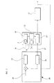
- FIG. 3 shows an engine control scheme in accordance with an embodiment of the present invention, in which an engine speed signal 23 indicative of the speed at which the engine is running is fed back to the pressure control unit 22. If a pressure sensor fault is detected, the control current 16 supplied by the pressure control unit 22 to move the metering valve member 4 a to the desired position is varied in response to the measured engine speed signal 23. The measured engine speed signal 23 is also fed back to the injection control unit 24. Upon detection of a fault condition, the control unit 20 prompts the injection control unit 24 to supply a constant, predetermined injection current to the injector 14 determined by a pre-set engine speed demand signal 30. The predetermined injection current supplied to the injector 14 sets a substantially fixed duration for which an injection of fuel occurs.
- the amount of fuel delivered by an injector 14 to the engine 15 is determined by the injection current 27 supplied by the injection control unit 24 and the pressure of fuel within the common rail 12.
- the injection current 27 supplied by the injection control unit 24 is maintained at the constant predetermined current, the quantity of fuel delivered by an injector 14 depends only on rail pressure.
- the measured engine speed signal 23 is fed back to the pressure control unit 22 such that, if the measured engine speed falls below the demanded engine speed signal 30, the current 16 supplied to the metering valve arrangement 4 is increased so as to increase the rate of flow of fuel to the high pressure pump 10.
- the rate of flow of fuel into the common rail 12 is therefore also increased, thereby increasing the pressure of fuel within the common rail 12.
- the engine speed demand signal 30 is preferably selected to be a speed greater than the usual idling speed of the engine, typically 1,200 rpm. In this way, the engine speed is maintained at a speed sufficient to enable the vehicle to be driven to a service centre or other safe location.
- the pressure control unit 22 responds by reducing the current 16 supplied to the metering valve arrangement, thereby reducing the rate of flow of fuel to the high pressure pump 10, and hence to the common rail 12, so as to reduce the pressure of fuel delivered to the injector 14. As a result, the amount of fuel delivered to the engine 15 is reduced, thereby causing the engine speed to be reduced.
- the injection current 27 supplied to the injector 14 at a substantially constant value and by varying the pressure of fuel within the common rail 12 in response to any deviation of the engine speed from the demanded engine speed, it is possible to maintain operation of the engine even in the event that a fault condition occurs in the pressure sensor 18.
- the invention provides the advantage that, even in common rail fuel systems which are not provided with a pressure regulating valve, it is possible to provide a limp-home capability in the event that failure of the rail pressure sensor occurs.
- the method of the present invention is not limited to use in a common rail system, but may be employed in any high pressure fuel system for delivering fuel to an engine.
- reference to the occurrence of a fault in the pressure sensor shall be taken to mean any degree of failure of the sensor including, but not limited to, operation of the pressure sensor being terminated.
Landscapes
- Engineering & Computer Science (AREA)
- Chemical & Material Sciences (AREA)
- Combustion & Propulsion (AREA)
- Mechanical Engineering (AREA)
- General Engineering & Computer Science (AREA)
- Electrical Control Of Air Or Fuel Supplied To Internal-Combustion Engine (AREA)
- Fuel-Injection Apparatus (AREA)
- Combined Controls Of Internal Combustion Engines (AREA)
- Crystals, And After-Treatments Of Crystals (AREA)
- Mechanical Treatment Of Semiconductor (AREA)
Claims (12)
Applications Claiming Priority (2)
| Application Number | Priority Date | Filing Date | Title |
|---|---|---|---|
| GB0104213 | 2001-02-21 | ||
| GB0104213A GB2372583A (en) | 2001-02-21 | 2001-02-21 | High pressure fuel injected engine limp home control system |
Publications (3)
| Publication Number | Publication Date |
|---|---|
| EP1234971A2 EP1234971A2 (fr) | 2002-08-28 |
| EP1234971A3 EP1234971A3 (fr) | 2004-01-07 |
| EP1234971B1 true EP1234971B1 (fr) | 2006-01-04 |
Family
ID=9909166
Family Applications (1)
| Application Number | Title | Priority Date | Filing Date |
|---|---|---|---|
| EP02251067A Expired - Lifetime EP1234971B1 (fr) | 2001-02-21 | 2002-02-16 | Procédé de commande pour un système d'injection à rampe d'alimentation commune en cas de defaillance de capteur de pression |
Country Status (5)
| Country | Link |
|---|---|
| US (1) | US6578555B2 (fr) |
| EP (1) | EP1234971B1 (fr) |
| AT (1) | ATE315172T1 (fr) |
| DE (1) | DE60208499T2 (fr) |
| GB (1) | GB2372583A (fr) |
Cited By (1)
| Publication number | Priority date | Publication date | Assignee | Title |
|---|---|---|---|---|
| CN101492051B (zh) * | 2009-01-07 | 2011-07-27 | 潍柴动力股份有限公司 | 用于控制车辆的方法和系统 |
Families Citing this family (30)
| Publication number | Priority date | Publication date | Assignee | Title |
|---|---|---|---|---|
| AUPQ489999A0 (en) * | 1999-12-24 | 2000-02-03 | Orbital Engine Company (Australia) Proprietary Limited | Improved speed limiter |
| GB0206259D0 (en) * | 2002-03-16 | 2002-05-01 | Delphi Tech Inc | Control method for injection using function map |
| US6581574B1 (en) * | 2002-03-27 | 2003-06-24 | Visteon Global Technologies, Inc. | Method for controlling fuel rail pressure |
| US6948486B2 (en) * | 2002-06-28 | 2005-09-27 | Fleetguard, Inc. | System and method for derating an engine to encourage servicing of a vehicle |
| US6799559B2 (en) * | 2002-08-30 | 2004-10-05 | Delphi Technologies, Inc. | Method and apparatus for controlling a dual coil fuel injector |
| JP2006200478A (ja) * | 2005-01-21 | 2006-08-03 | Denso Corp | 燃料噴射装置 |
| US7007676B1 (en) | 2005-01-31 | 2006-03-07 | Caterpillar Inc. | Fuel system |
| US7788015B2 (en) * | 2007-12-20 | 2010-08-31 | Cummins Inc. | System for monitoring injected fuel quantities |
| DE112009001000B4 (de) * | 2008-05-02 | 2017-08-24 | GM Global Technology Operations LLC (n. d. Ges. d. Staates Delaware) | Verbesserungen einer HCCI-Verbrennungssteuerung bei leichter Last und im Leerlauf durch Modifikation des Kraftstoffdrucks |
| DE102008035985B4 (de) * | 2008-08-01 | 2010-07-08 | Continental Automotive Gmbh | Verfahren und Vorrichtung zur Regelung des Kraftstoffdruckes im Druckspeicher eines Common-Rail-Einspritzsystems |
| US7832375B2 (en) * | 2008-11-06 | 2010-11-16 | Ford Global Technologies, Llc | Addressing fuel pressure uncertainty during startup of a direct injection engine |
| JP4909973B2 (ja) * | 2008-11-14 | 2012-04-04 | 日立オートモティブシステムズ株式会社 | 内燃機関の制御装置 |
| US8281768B2 (en) * | 2009-03-04 | 2012-10-09 | GM Global Technology Operations LLC | Method and apparatus for controlling fuel rail pressure using fuel pressure sensor error |
| US8091532B2 (en) * | 2009-04-22 | 2012-01-10 | GM Global Technology Operations LLC | Diagnostic systems and methods for a pressure sensor during driving conditions |
| EP2440785B1 (fr) * | 2009-06-12 | 2014-01-08 | Mahle International GmbH | Système de pompage de lubrifiant |
| DE102009050468B4 (de) * | 2009-10-23 | 2017-03-16 | Mtu Friedrichshafen Gmbh | Verfahren zur Steuerung und Regelung einer Brennkraftmaschine |
| DE102009050469B4 (de) * | 2009-10-23 | 2015-11-05 | Mtu Friedrichshafen Gmbh | Verfahren zur Steuerung und Regelung einer Brennkraftmaschine |
| JP5267446B2 (ja) * | 2009-12-22 | 2013-08-21 | 日産自動車株式会社 | 内燃機関の燃料供給装置 |
| DE102010031220A1 (de) * | 2010-07-12 | 2012-01-12 | Robert Bosch Gmbh | Verfahren und Vorrichtung zum Betreiben eines Kraftstoffeinspritzsystems |
| EP2655856B1 (fr) * | 2010-12-22 | 2019-10-02 | Volvo Lastvagnar AB | Système d'injection de carburant comprenant une pompe haute pression d'injection de carburant |
| DE102012200457A1 (de) * | 2011-03-03 | 2012-09-06 | Robert Bosch Gmbh | Verfahren zum Bestimmen einer Temperatur von Kraftstoff |
| DE102011077991A1 (de) | 2011-06-22 | 2012-12-27 | Robert Bosch Gmbh | Verfahren zum Betreiben einer Kraftstofffördereinrichtung einer Brennkraftmaschine |
| JP6406124B2 (ja) * | 2015-05-26 | 2018-10-17 | 株式会社デンソー | 内燃機関の高圧ポンプ制御装置 |
| WO2017064360A1 (fr) * | 2015-10-16 | 2017-04-20 | Wärtsilä Finland Oy | Procédé dans une procédure de démarrage d'un moteur à piston à combustion interne pourvu d'un système d'injection à rampe commune |
| CN112196685A (zh) * | 2020-09-29 | 2021-01-08 | 东风商用车有限公司 | 一种介入式轨压传感器故障诊断方法及装置 |
| CN114856844A (zh) * | 2020-10-01 | 2022-08-05 | 罗伯特·博世有限公司 | 检测燃料喷射系统的低压回路中的故障的方法 |
| CN112253322B (zh) * | 2020-10-20 | 2022-05-31 | 东风汽车集团有限公司 | 基于油轨压力传感器故障的发动机控制方法 |
| CN112412673B (zh) * | 2020-10-27 | 2022-04-26 | 潍柴动力股份有限公司 | 燃油系统、发动机及自动解除发动机跛行模式的方法 |
| CN114592984B (zh) * | 2022-03-14 | 2023-08-18 | 潍柴动力股份有限公司 | 一种轨压传感器校验方法、装置和设备 |
| CN118481854B (zh) * | 2024-05-29 | 2026-03-31 | 东风商用车有限公司 | 燃油计量阀流量特性自学习方法、装置及存储介质 |
Family Cites Families (9)
| Publication number | Priority date | Publication date | Assignee | Title |
|---|---|---|---|---|
| CH674243A5 (fr) * | 1987-07-08 | 1990-05-15 | Dereco Dieselmotoren Forschung | |
| JP3564148B2 (ja) * | 1992-05-08 | 2004-09-08 | 株式会社ボッシュオートモーティブシステム | 内燃機関の燃料噴射制御システム |
| DE19612412B4 (de) * | 1996-03-28 | 2006-07-06 | Siemens Ag | Regelung für ein Druckfluid-Versorgungssystem, insbesondere für den Hochdruck in einem Kraftstoff-Einspritzsystem |
| US6024064A (en) * | 1996-08-09 | 2000-02-15 | Denso Corporation | High pressure fuel injection system for internal combustion engine |
| JP3680515B2 (ja) * | 1997-08-28 | 2005-08-10 | 日産自動車株式会社 | 内燃機関の燃料系診断装置 |
| US6053147A (en) * | 1998-03-02 | 2000-04-25 | Cummins Engine Company, Inc. | Apparatus and method for diagnosing erratic pressure sensor operation in a fuel system of an internal combustion engine |
| US5937826A (en) * | 1998-03-02 | 1999-08-17 | Cummins Engine Company, Inc. | Apparatus for controlling a fuel system of an internal combustion engine |
| JPH11324854A (ja) * | 1998-05-19 | 1999-11-26 | Mitsubishi Electric Corp | 蓄圧式燃料噴射装置 |
| DE19916100A1 (de) * | 1999-04-09 | 2000-10-12 | Bosch Gmbh Robert | Verfahren und Vorrichtung zur Steuerung einer Brennkraftmaschine |
-
2001
- 2001-02-21 GB GB0104213A patent/GB2372583A/en not_active Withdrawn
-
2002
- 2002-02-16 EP EP02251067A patent/EP1234971B1/fr not_active Expired - Lifetime
- 2002-02-16 AT AT02251067T patent/ATE315172T1/de not_active IP Right Cessation
- 2002-02-16 DE DE60208499T patent/DE60208499T2/de not_active Expired - Lifetime
- 2002-02-20 US US10/079,672 patent/US6578555B2/en not_active Expired - Fee Related
Cited By (1)
| Publication number | Priority date | Publication date | Assignee | Title |
|---|---|---|---|---|
| CN101492051B (zh) * | 2009-01-07 | 2011-07-27 | 潍柴动力股份有限公司 | 用于控制车辆的方法和系统 |
Also Published As
| Publication number | Publication date |
|---|---|
| DE60208499T2 (de) | 2006-09-14 |
| ATE315172T1 (de) | 2006-02-15 |
| US6578555B2 (en) | 2003-06-17 |
| EP1234971A3 (fr) | 2004-01-07 |
| US20020117150A1 (en) | 2002-08-29 |
| EP1234971A2 (fr) | 2002-08-28 |
| DE60208499D1 (de) | 2006-03-30 |
| GB2372583A (en) | 2002-08-28 |
| GB0104213D0 (en) | 2001-04-11 |
Similar Documents
| Publication | Publication Date | Title |
|---|---|---|
| EP1234971B1 (fr) | Procédé de commande pour un système d'injection à rampe d'alimentation commune en cas de defaillance de capteur de pression | |
| EP2187029B1 (fr) | Appareil de contrôle pour moteur à combustion interne | |
| EP2235352B1 (fr) | Système et procédé de prévention de surchauffe de pompe à carburant | |
| US6016791A (en) | Method and system for controlling fuel pressure in a common rail fuel injection system | |
| US6142120A (en) | Process and device for controlling an internal combustion engine | |
| CN107448315B (zh) | 用于控制和调节内燃机的方法 | |
| JP2002541383A (ja) | 内燃機関の制御方法及び装置 | |
| US7302935B2 (en) | Method for operating an internal combustion engine, fuel system, and volume flow control valve | |
| CN102762843B (zh) | 用于控制和调节v形布置的内燃机的方法 | |
| JP2000511992A (ja) | 内燃エンジンの燃料システムを制御する装置 | |
| CN100434682C (zh) | 确定喷油阀压电执行器的控制电压的方法 | |
| CN100434683C (zh) | 用于监控燃料喷射系统功能能力的方法 | |
| KR100696085B1 (ko) | 차량의 내연기관 작동시스템 | |
| CN102112722B (zh) | 调节共轨喷射系统的蓄压器中的燃料压力的方法和装置 | |
| CN117418955A (zh) | 燃料喷射器可变性降低 | |
| JP4750978B2 (ja) | 供給燃料の漏れ検出方法 | |
| CN112196685A (zh) | 一种介入式轨压传感器故障诊断方法及装置 | |
| US7814887B2 (en) | Method and device for controlling a pump connected to a fuel rail | |
| JPH08232790A (ja) | 内燃機関のための燃料供給装置 | |
| KR101858785B1 (ko) | 내연 기관의 레일 압력을 제어하는 방법 | |
| JPS61142346A (ja) | 内燃機関の電子制御式燃料噴射装置 | |
| JP4566450B2 (ja) | 蓄圧式燃料噴射装置 | |
| JP3900903B2 (ja) | 蓄圧式燃料噴射装置 | |
| CN102686860B (zh) | 用于防止配备有柴油喷射系统的车辆的发动机熄火的装置 | |
| JP4062721B2 (ja) | 蓄圧式燃料噴射装置 |
Legal Events
| Date | Code | Title | Description |
|---|---|---|---|
| PUAI | Public reference made under article 153(3) epc to a published international application that has entered the european phase |
Free format text: ORIGINAL CODE: 0009012 |
|
| AK | Designated contracting states |
Kind code of ref document: A2 Designated state(s): AT BE CH CY DE DK ES FI FR GB GR IE IT LI LU MC NL PT SE TR |
|
| AX | Request for extension of the european patent |
Free format text: AL;LT;LV;MK;RO;SI |
|
| PUAL | Search report despatched |
Free format text: ORIGINAL CODE: 0009013 |
|
| AK | Designated contracting states |
Kind code of ref document: A3 Designated state(s): AT BE CH CY DE DK ES FI FR GB GR IE IT LI LU MC NL PT SE TR |
|
| AX | Request for extension of the european patent |
Extension state: AL LT LV MK RO SI |
|
| RIC1 | Information provided on ipc code assigned before grant |
Ipc: 7F 02D 41/22 A |
|
| 17P | Request for examination filed |
Effective date: 20040420 |
|
| 17Q | First examination report despatched |
Effective date: 20040617 |
|
| AKX | Designation fees paid |
Designated state(s): AT BE CH CY DE DK ES FI FR GB GR IE IT LI LU MC NL PT SE TR |
|
| RTI1 | Title (correction) |
Free format text: CONTROL METHOD FOR A COMMON RAIL FUEL INJECTION SYSTEM IN CASE OF RAIL PRESSURE SENSOR FAULT |
|
| GRAP | Despatch of communication of intention to grant a patent |
Free format text: ORIGINAL CODE: EPIDOSNIGR1 |
|
| GRAS | Grant fee paid |
Free format text: ORIGINAL CODE: EPIDOSNIGR3 |
|
| GRAA | (expected) grant |
Free format text: ORIGINAL CODE: 0009210 |
|
| AK | Designated contracting states |
Kind code of ref document: B1 Designated state(s): AT BE CH CY DE DK ES FI FR GB GR IE IT LI LU MC NL PT SE TR |
|
| PG25 | Lapsed in a contracting state [announced via postgrant information from national office to epo] |
Ref country code: CH Free format text: LAPSE BECAUSE OF FAILURE TO SUBMIT A TRANSLATION OF THE DESCRIPTION OR TO PAY THE FEE WITHIN THE PRESCRIBED TIME-LIMIT Effective date: 20060104 Ref country code: NL Free format text: LAPSE BECAUSE OF FAILURE TO SUBMIT A TRANSLATION OF THE DESCRIPTION OR TO PAY THE FEE WITHIN THE PRESCRIBED TIME-LIMIT Effective date: 20060104 Ref country code: FI Free format text: LAPSE BECAUSE OF FAILURE TO SUBMIT A TRANSLATION OF THE DESCRIPTION OR TO PAY THE FEE WITHIN THE PRESCRIBED TIME-LIMIT Effective date: 20060104 Ref country code: BE Free format text: LAPSE BECAUSE OF FAILURE TO SUBMIT A TRANSLATION OF THE DESCRIPTION OR TO PAY THE FEE WITHIN THE PRESCRIBED TIME-LIMIT Effective date: 20060104 Ref country code: AT Free format text: LAPSE BECAUSE OF FAILURE TO SUBMIT A TRANSLATION OF THE DESCRIPTION OR TO PAY THE FEE WITHIN THE PRESCRIBED TIME-LIMIT Effective date: 20060104 Ref country code: LI Free format text: LAPSE BECAUSE OF FAILURE TO SUBMIT A TRANSLATION OF THE DESCRIPTION OR TO PAY THE FEE WITHIN THE PRESCRIBED TIME-LIMIT Effective date: 20060104 |
|
| REG | Reference to a national code |
Ref country code: GB Ref legal event code: FG4D |
|
| REG | Reference to a national code |
Ref country code: CH Ref legal event code: EP |
|
| REG | Reference to a national code |
Ref country code: IE Ref legal event code: FG4D |
|
| PG25 | Lapsed in a contracting state [announced via postgrant information from national office to epo] |
Ref country code: IE Free format text: LAPSE BECAUSE OF NON-PAYMENT OF DUE FEES Effective date: 20060216 |
|
| PG25 | Lapsed in a contracting state [announced via postgrant information from national office to epo] |
Ref country code: MC Free format text: LAPSE BECAUSE OF NON-PAYMENT OF DUE FEES Effective date: 20060228 |
|
| PG25 | Lapsed in a contracting state [announced via postgrant information from national office to epo] |
Ref country code: LU Free format text: LAPSE BECAUSE OF NON-PAYMENT OF DUE FEES Effective date: 20060304 |
|
| REF | Corresponds to: |
Ref document number: 60208499 Country of ref document: DE Date of ref document: 20060330 Kind code of ref document: P |
|
| PG25 | Lapsed in a contracting state [announced via postgrant information from national office to epo] |
Ref country code: GB Free format text: LAPSE BECAUSE OF NON-PAYMENT OF DUE FEES Effective date: 20060404 Ref country code: DK Free format text: LAPSE BECAUSE OF FAILURE TO SUBMIT A TRANSLATION OF THE DESCRIPTION OR TO PAY THE FEE WITHIN THE PRESCRIBED TIME-LIMIT Effective date: 20060404 Ref country code: SE Free format text: LAPSE BECAUSE OF FAILURE TO SUBMIT A TRANSLATION OF THE DESCRIPTION OR TO PAY THE FEE WITHIN THE PRESCRIBED TIME-LIMIT Effective date: 20060404 |
|
| PG25 | Lapsed in a contracting state [announced via postgrant information from national office to epo] |
Ref country code: ES Free format text: LAPSE BECAUSE OF FAILURE TO SUBMIT A TRANSLATION OF THE DESCRIPTION OR TO PAY THE FEE WITHIN THE PRESCRIBED TIME-LIMIT Effective date: 20060415 |
|
| ET | Fr: translation filed | ||
| PG25 | Lapsed in a contracting state [announced via postgrant information from national office to epo] |
Ref country code: PT Free format text: LAPSE BECAUSE OF FAILURE TO SUBMIT A TRANSLATION OF THE DESCRIPTION OR TO PAY THE FEE WITHIN THE PRESCRIBED TIME-LIMIT Effective date: 20060605 |
|
| NLV1 | Nl: lapsed or annulled due to failure to fulfill the requirements of art. 29p and 29m of the patents act | ||
| REG | Reference to a national code |
Ref country code: CH Ref legal event code: PL |
|
| PLBE | No opposition filed within time limit |
Free format text: ORIGINAL CODE: 0009261 |
|
| STAA | Information on the status of an ep patent application or granted ep patent |
Free format text: STATUS: NO OPPOSITION FILED WITHIN TIME LIMIT |
|
| 26N | No opposition filed |
Effective date: 20061005 |
|
| GBPC | Gb: european patent ceased through non-payment of renewal fee |
Effective date: 20060404 |
|
| PG25 | Lapsed in a contracting state [announced via postgrant information from national office to epo] |
Ref country code: GR Free format text: LAPSE BECAUSE OF FAILURE TO SUBMIT A TRANSLATION OF THE DESCRIPTION OR TO PAY THE FEE WITHIN THE PRESCRIBED TIME-LIMIT Effective date: 20060405 |
|
| PG25 | Lapsed in a contracting state [announced via postgrant information from national office to epo] |
Ref country code: TR Free format text: LAPSE BECAUSE OF FAILURE TO SUBMIT A TRANSLATION OF THE DESCRIPTION OR TO PAY THE FEE WITHIN THE PRESCRIBED TIME-LIMIT Effective date: 20060104 |
|
| PG25 | Lapsed in a contracting state [announced via postgrant information from national office to epo] |
Ref country code: CY Free format text: LAPSE BECAUSE OF FAILURE TO SUBMIT A TRANSLATION OF THE DESCRIPTION OR TO PAY THE FEE WITHIN THE PRESCRIBED TIME-LIMIT Effective date: 20060104 |
|
| REG | Reference to a national code |
Ref country code: FR Ref legal event code: TP |
|
| REG | Reference to a national code |
Ref country code: FR Ref legal event code: TP Owner name: DELPHI INTERNATIONAL OPERATIONS LUXEMBOURG S.A, LU Effective date: 20140516 |
|
| REG | Reference to a national code |
Ref country code: DE Ref legal event code: R082 Ref document number: 60208499 Country of ref document: DE Representative=s name: MANITZ, FINSTERWALD & PARTNER GBR, DE |
|
| REG | Reference to a national code |
Ref country code: DE Ref legal event code: R081 Ref document number: 60208499 Country of ref document: DE Owner name: DELPHI INTERNATIONAL OPERATIONS LUXEMBOURG S.A, LU Free format text: FORMER OWNER: DELPHI TECHNOLOGIES HOLDING S.A.R.L., BASCHARAGE, LU Effective date: 20140702 Ref country code: DE Ref legal event code: R082 Ref document number: 60208499 Country of ref document: DE Representative=s name: MANITZ, FINSTERWALD & PARTNER GBR, DE Effective date: 20140702 Ref country code: DE Ref legal event code: R082 Ref document number: 60208499 Country of ref document: DE Representative=s name: MANITZ FINSTERWALD PATENTANWAELTE PARTMBB, DE Effective date: 20140702 |
|
| REG | Reference to a national code |
Ref country code: FR Ref legal event code: PLFP Year of fee payment: 15 |
|
| REG | Reference to a national code |
Ref country code: FR Ref legal event code: PLFP Year of fee payment: 16 |
|
| REG | Reference to a national code |
Ref country code: FR Ref legal event code: PLFP Year of fee payment: 17 |
|
| REG | Reference to a national code |
Ref country code: DE Ref legal event code: R082 Ref document number: 60208499 Country of ref document: DE Ref country code: DE Ref legal event code: R081 Ref document number: 60208499 Country of ref document: DE Owner name: DELPHI TECHNOLOGIES IP LIMITED, BB Free format text: FORMER OWNER: DELPHI INTERNATIONAL OPERATIONS LUXEMBOURG S.A R.L., BASCHARAGE, LU |
|
| PGFP | Annual fee paid to national office [announced via postgrant information from national office to epo] |
Ref country code: FR Payment date: 20210223 Year of fee payment: 20 Ref country code: IT Payment date: 20210219 Year of fee payment: 20 |
|
| PGFP | Annual fee paid to national office [announced via postgrant information from national office to epo] |
Ref country code: DE Payment date: 20210225 Year of fee payment: 20 |
|
| REG | Reference to a national code |
Ref country code: DE Ref legal event code: R071 Ref document number: 60208499 Country of ref document: DE |