EP1234615B1 - Brausekopf - Google Patents
Brausekopf Download PDFInfo
- Publication number
- EP1234615B1 EP1234615B1 EP02003043A EP02003043A EP1234615B1 EP 1234615 B1 EP1234615 B1 EP 1234615B1 EP 02003043 A EP02003043 A EP 02003043A EP 02003043 A EP02003043 A EP 02003043A EP 1234615 B1 EP1234615 B1 EP 1234615B1
- Authority
- EP
- European Patent Office
- Prior art keywords
- annular channel
- shut
- spray head
- water outlet
- outlet openings
- Prior art date
- Legal status (The legal status is an assumption and is not a legal conclusion. Google has not performed a legal analysis and makes no representation as to the accuracy of the status listed.)
- Expired - Lifetime
Links
Images


Classifications
-
- B—PERFORMING OPERATIONS; TRANSPORTING
- B05—SPRAYING OR ATOMISING IN GENERAL; APPLYING FLUENT MATERIALS TO SURFACES, IN GENERAL
- B05B—SPRAYING APPARATUS; ATOMISING APPARATUS; NOZZLES
- B05B1/00—Nozzles, spray heads or other outlets, with or without auxiliary devices such as valves, heating means
- B05B1/02—Nozzles, spray heads or other outlets, with or without auxiliary devices such as valves, heating means designed to produce a jet, spray, or other discharge of particular shape or nature, e.g. in single drops, or having an outlet of particular shape
- B05B1/08—Nozzles, spray heads or other outlets, with or without auxiliary devices such as valves, heating means designed to produce a jet, spray, or other discharge of particular shape or nature, e.g. in single drops, or having an outlet of particular shape of pulsating nature, e.g. delivering liquid in successive separate quantities
- B05B1/083—Nozzles, spray heads or other outlets, with or without auxiliary devices such as valves, heating means designed to produce a jet, spray, or other discharge of particular shape or nature, e.g. in single drops, or having an outlet of particular shape of pulsating nature, e.g. delivering liquid in successive separate quantities the pulsating mechanism comprising movable parts
- B05B1/085—Nozzles, spray heads or other outlets, with or without auxiliary devices such as valves, heating means designed to produce a jet, spray, or other discharge of particular shape or nature, e.g. in single drops, or having an outlet of particular shape of pulsating nature, e.g. delivering liquid in successive separate quantities the pulsating mechanism comprising movable parts rotated by the liquid or other fluent material discharged, e.g. liquid rotated turbines
- B05B1/0852—Nozzles, spray heads or other outlets, with or without auxiliary devices such as valves, heating means designed to produce a jet, spray, or other discharge of particular shape or nature, e.g. in single drops, or having an outlet of particular shape of pulsating nature, e.g. delivering liquid in successive separate quantities the pulsating mechanism comprising movable parts rotated by the liquid or other fluent material discharged, e.g. liquid rotated turbines the liquid or other fluent material actuating several pulsating mechanisms
-
- B—PERFORMING OPERATIONS; TRANSPORTING
- B05—SPRAYING OR ATOMISING IN GENERAL; APPLYING FLUENT MATERIALS TO SURFACES, IN GENERAL
- B05B—SPRAYING APPARATUS; ATOMISING APPARATUS; NOZZLES
- B05B1/00—Nozzles, spray heads or other outlets, with or without auxiliary devices such as valves, heating means
- B05B1/02—Nozzles, spray heads or other outlets, with or without auxiliary devices such as valves, heating means designed to produce a jet, spray, or other discharge of particular shape or nature, e.g. in single drops, or having an outlet of particular shape
- B05B1/08—Nozzles, spray heads or other outlets, with or without auxiliary devices such as valves, heating means designed to produce a jet, spray, or other discharge of particular shape or nature, e.g. in single drops, or having an outlet of particular shape of pulsating nature, e.g. delivering liquid in successive separate quantities
- B05B1/083—Nozzles, spray heads or other outlets, with or without auxiliary devices such as valves, heating means designed to produce a jet, spray, or other discharge of particular shape or nature, e.g. in single drops, or having an outlet of particular shape of pulsating nature, e.g. delivering liquid in successive separate quantities the pulsating mechanism comprising movable parts
- B05B1/085—Nozzles, spray heads or other outlets, with or without auxiliary devices such as valves, heating means designed to produce a jet, spray, or other discharge of particular shape or nature, e.g. in single drops, or having an outlet of particular shape of pulsating nature, e.g. delivering liquid in successive separate quantities the pulsating mechanism comprising movable parts rotated by the liquid or other fluent material discharged, e.g. liquid rotated turbines
- B05B1/0856—Nozzles, spray heads or other outlets, with or without auxiliary devices such as valves, heating means designed to produce a jet, spray, or other discharge of particular shape or nature, e.g. in single drops, or having an outlet of particular shape of pulsating nature, e.g. delivering liquid in successive separate quantities the pulsating mechanism comprising movable parts rotated by the liquid or other fluent material discharged, e.g. liquid rotated turbines the pulsating mechanism comprising movable balls
-
- B—PERFORMING OPERATIONS; TRANSPORTING
- B05—SPRAYING OR ATOMISING IN GENERAL; APPLYING FLUENT MATERIALS TO SURFACES, IN GENERAL
- B05B—SPRAYING APPARATUS; ATOMISING APPARATUS; NOZZLES
- B05B1/00—Nozzles, spray heads or other outlets, with or without auxiliary devices such as valves, heating means
- B05B1/14—Nozzles, spray heads or other outlets, with or without auxiliary devices such as valves, heating means with multiple outlet openings; with strainers in or outside the outlet opening
- B05B1/16—Nozzles, spray heads or other outlets, with or without auxiliary devices such as valves, heating means with multiple outlet openings; with strainers in or outside the outlet opening having selectively- effective outlets
- B05B1/1627—Nozzles, spray heads or other outlets, with or without auxiliary devices such as valves, heating means with multiple outlet openings; with strainers in or outside the outlet opening having selectively- effective outlets with a selecting mechanism comprising a gate valve, a sliding valve or a cock
- B05B1/1636—Nozzles, spray heads or other outlets, with or without auxiliary devices such as valves, heating means with multiple outlet openings; with strainers in or outside the outlet opening having selectively- effective outlets with a selecting mechanism comprising a gate valve, a sliding valve or a cock by relative rotative movement of the valve elements
- B05B1/1645—Nozzles, spray heads or other outlets, with or without auxiliary devices such as valves, heating means with multiple outlet openings; with strainers in or outside the outlet opening having selectively- effective outlets with a selecting mechanism comprising a gate valve, a sliding valve or a cock by relative rotative movement of the valve elements the outlets being rotated during selection
- B05B1/1654—Nozzles, spray heads or other outlets, with or without auxiliary devices such as valves, heating means with multiple outlet openings; with strainers in or outside the outlet opening having selectively- effective outlets with a selecting mechanism comprising a gate valve, a sliding valve or a cock by relative rotative movement of the valve elements the outlets being rotated during selection about an axis parallel to the liquid passage in the stationary valve element
-
- B—PERFORMING OPERATIONS; TRANSPORTING
- B05—SPRAYING OR ATOMISING IN GENERAL; APPLYING FLUENT MATERIALS TO SURFACES, IN GENERAL
- B05B—SPRAYING APPARATUS; ATOMISING APPARATUS; NOZZLES
- B05B1/00—Nozzles, spray heads or other outlets, with or without auxiliary devices such as valves, heating means
- B05B1/14—Nozzles, spray heads or other outlets, with or without auxiliary devices such as valves, heating means with multiple outlet openings; with strainers in or outside the outlet opening
- B05B1/18—Roses; Shower heads
Definitions
- the invention relates to a shower head for generating pulsating shower jets, in particular for the water massage, with at least one water outlet openings having annular channel in which a blocking body is arranged for the water outlet openings, wherein the shower water flows tangentially or inclined to the axis of rotation in the annular channel, so that the locking body circulates in the annular channel.
- a shower device is known.
- a shuttle is provided as a blocking body, which simultaneously covers three water outlet openings and is slidably disposed in the annular channel.
- the plain bearing of the shuttle requires a relatively high drive energy, which should increase correspondingly with the increase of the simultaneously to be covered water outlet openings to the locking body in the annular channel to circulate and hold.
- an improvement of the Pulsator Sign the shower jets can be achieved by simultaneously covering as many water outlet openings.
- the invention is based on the object to provide a smooth and low-wear rotating locking body for the simultaneous coverage of several water outlet openings.
- the frictional resistance can be considerably reduced by the arrangement of rolling elements, so that the blocking body can be dimensioned so that a larger number of water outlet openings are concealed simultaneously.
- the blocking body can be arranged expediently on a ring which can be inserted into the annular channel, wherein advantageously three symmetrically arranged cages for receiving three rolling elements are formed in the region of the ring are.
- the rolling elements can advantageously be formed spherical or conical.
- the ring with the locking body and the cages can be made in one piece from plastic by injection molding, wherein the locking body is arranged on the ring so that it is held by the rolling elements in the annular channel with little play to the shower base of the annular channel.
- two or more concentrically arranged annular channels can be provided, in each of which the rotating locking body can be arranged independently, wherein alternatively also on the one hand, a blocking body which simultaneously covers a plurality of water outlet openings, and on the other hand as a blocking body a rotating ball, the only briefly covers a respective water outlet, can be used.
- the connection of the individual concentrically arranged annular channels is advantageously carried out via guide nozzles, which align the inflowing water again tangentially before the inlet in the next annular channel.
- the blocking body according to the invention can be arranged with the ring channel training in a shower head, in which further spray jet generating systems, for example, one or more means for generating non-pulsating shower jets, are provided.
- This can be provided with a switching valve respectively the inflowing Be supplied shower water to the desired shower jet generating system.
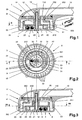
- an approximately cup-shaped shower head housing 1 is provided on the side of a partially illustrated handle 10 is formed.
- a rotationally fixed and sealed with an O-ring arranged plate 11 is provided in the eccentric to the central axis 13, a passage opening 110 is provided for the incoming shower water.
- the downstream open shower head housing 1 is closed by a shower tray 2.
- the shower base 2 is rotatable by a central screw 12 axially to the showerhead housing 1, but held axially fixed, with a trained on the shower tray 2 circumferential collar 23 surrounds the showerhead housing 1 sealed with an O-ring.
- a water guide body 25 is sealed at the upstream side and held against rotation.
- the water guide body 25 is eccentric with a corresponding to the passage opening 110 formed inlet opening 250 and a surrounding the inlet opening 250 in the end face O-ring 253, such that in the rotational position shown in Fig. 1, the incoming effervescent water flows from the passage opening 110 in the inlet opening 250 of the water guide body 25 and into an inner annulus 252nd arrives. If, in contrast, the shower base 2 is rotated by 180 ° with the water guide body 25, as shown in Fig. 3 of the drawing, the inlet opening 250 is shut off by the plate 11, while the shower water through the passage opening 110 in an outer annular space 251 of the shower base 2 flows in.
- the outer annular space 251 is connected downstream with a ring of water outlet openings 20, with which non-pulsating continuous spray jets can be generated.
- the inner annular space 252 is connected via guide nozzles 22 with two concentrically arranged annular channels 21.
- a circular array of water outlet openings 20 passing through the shower base 2 is provided, which is partially covered by a blocking body 3, which circulates with the inflowing water in the annular channel 21, so that effervescent jets issuing in a pulsating manner are produced.
- the blocking body 3 is integrated in a ring 30 having a considerably smaller cross-section and releasing the water outlet openings.
- the blocking body 3 is dimensioned in this way, that it covers about one third of the total number of water outlet openings 20 in the shower tray 2 of the annular channel 21.
- three symmetrically arranged cages 31 are formed in the ring 30, which serve as a receptacle each formed as a ball rolling element 4.
- the locking body 3 is made together with the ring 30 and the three cages 31 in one piece from plastic by injection molding.
- the three trained as balls rolling elements 4 are guided in the annular channel 21 in a recessed into the shower tray 2 groove 210.
- In the inner annular channel 21 is arranged as a blocking body 3, only a ball.
- a reduced diameter exhibiting locking body may be provided.
- the hand shower described above has the following operation:
- the shower water is introduced from a hose line, not shown in the drawing in the handle 10 shown in part of the hand shower.
- the inlet opening 250 of the water guide body 25 with the passage opening 110 of the plate 11 is in registration, so that the incoming shower water enters the inner annular space 252.
- Fig. 2 of the drawing which is in the annulus 252 located shower water through a Leitdüse 22 tangentially fed into the outer annular channel 21, whereby the water flow in the annular channel 21, the ring 30 with the three cages 31, which act as blades in the water flow, and the locking body 3 in rotation.
- the encircling blocking body 3 covers in each case one third of the water outlet openings 20 or interrupts the passage of water, so that pulsating shower jets are generated circumferentially.
- effervescent water enters through the inside guide nozzles 22 in the inner annular channel 21 and offset by the tangential inflow the locking body 3 also in circumferential movement, so that the water outlet openings 20 are circumferentially temporarily covered in the inner annular channel 21. With the circumferential covering or closing of individual water outlet openings 20 pulsating shower jets are generated.
- the individual water outlet openings 20 can be closed for a longer time with the blocking body 3 according to the invention.
- the closing time is dependent on the size of the covering blocking body 3.
- the effect of the pulsating water jets can be adjusted as desired by the parameters: water pressure, water flow, size of the blocking body and number and size of the water outlet openings.
- the inlet opening 250 is shut off from the plate 11.
- the passage opening 110 is in this case connected to the outer annular space 251.
- the shower water flowing into the annular space 251 is discharged downstream through the ring of water outlet openings 20 provided in the shower base 2 as non-pulsating continuous spray jets.
- the embodiment shown in the drawing Fig. 4 and 5 differs from the above-described essentially in that only one annular channel 21 is formed and in the shower tray 2 of the annular channel 21, two concentrically arranged rings of water outlet openings 20 are provided.
- the locking body 3 is in this case formed so that it covers one third of the two circles with the water outlet openings 20, wherein the locking body 3 is provided with two rings 30 on the inside and outside, in which three symmetrically arranged cages 31. for the rolling elements. 4 are provided.
- the rolling elements 4 are in this case conical, so that circumferential grooves in the shower tray 2 can be omitted.
- this embodiment corresponds to the above.
- FIG. 6 and 7 another embodiment of a shower tray 2 is shown without shower head housing.
- the annular channel 21 is on the outside provided in the shower tray 2, while in the central region two rings of water outlet openings 20 are formed, from which continuous, non-pulsating shower jets can be delivered.
- the blocking body 3 also covers approximately one third of the circularly arranged water outlet openings 20.
- the locking body 3 is in this case guided smoothly again by three spherical rolling elements 4, wherein on the locking body 3 on the inside a reduced in cross-section ring 30 is formed on the three symmetrically arranged cages 31 are formed for the rolling elements 4.
- the rolling elements 4 are guided in a groove 210 in the shower tray 2.
- this can also be done by one or more inclined to the central axis of the showerhead housing 1 arranged nozzles. In order to achieve a smooth rotation and a good blocking effect of the locking body 3, this is expediently arranged with a small clearance 32 to the shower base 2 of the annular channel 21.
Landscapes
- Nozzles (AREA)
- Bathtubs, Showers, And Their Attachments (AREA)
- Massaging Devices (AREA)
- Cylinder Crankcases Of Internal Combustion Engines (AREA)
- Sewing Machines And Sewing (AREA)
- Crystals, And After-Treatments Of Crystals (AREA)
Description
- Die Erfindung betrifft einen Brausekopf zur Erzeugung von pulsierenden Brausestrahlen, insbesondere für die Wassermassage, mit wenigstens einem Wasseraustrittsöffnungen aufweisenden Ringkanal, in dem ein Sperrkörper für die Wasseraustrittsöffnungen angeordnet ist, wobei das Brausewasser tangential oder geneigt zur Umlaufachse in den Ringkanal einströmt, so dass der Sperrkörper in dem Ringkanal umläuft.
- Aus der Druckschrift EP 0 308 693 A1 ist eine derartige Brauseeinrichtung bekannt. Hierbei ist als Sperrkörper ein Schiffchen vorgesehen, das gleichzeitig drei Wasseraustrittsöffnungen abdeckt und gleitend in dem Ringkanal angeordnet ist. Die Gleitlagerung des Schiffchens erfordert jedoch eine relativ hohe Antriebsenergie, die sich mit der Zunahme der gleichzeitig abzudeckenden Wasseraustrittsöffnungen entsprechend vergrößern dürfte, um den Sperrkörper im Ringkanal in Umlaufbewegung zu bringen und zu halten. Andererseits kann eine Verbesserung der Pulsatorwirkung der Brausestrahlen durch ein gleichzeitiges Abdecken von möglichst vielen Wasseraustrittsöffnungen erreicht werden.
- Dokument US3762648 offenbart einen Brausekopf zur Erzeugung von pulsierenden Brausestrahlen durch ein Ventilrotor, welcher durch Wasser in Drehung versetzt wird. Für den Ventilrotor kann ein Wellenlager und ein Kugellager vorgesehen werden.
- Der Erfindung liegt die Aufgabe zu Grunde, einen leichtgängigen und verschleißarmen umlaufenden Sperrkörper für die gleichzeitige Abdeckung von mehreren Wasseraustrittsöffnungen zu schaffen.
- Diese Aufgabe wird erfindungsgemäß mit den Merkmalen des Anspruchs 1 gelöst.
Weitere Ausgestaltungen der Erfindung sind in den Ansprüchen 2 bis 10 angegeben. - Mit dem erfindungsgemäßen Sperrkörper kann der Reibwiderstand durch die Anordnung von Wälzkörpern erheblich verringert werden, so dass der Sperrkörper so dimensioniert werden kann, dass auch eine größere Zahl von Wasseraustrittsöffnungen gleichzeitig verdeckbar sind.
- Als vorteilhaft hat sich gezeigt, wenn von dem Sperrkörper etwa ein Drittel bis ein Viertel der Wasseraustrittsöffnungen gleichzeitig abgedeckt werden.
In weiterer Ausgestaltung der Erfindung kann der Sperrkörper zweckmäßig an einem in den Ringkanal einlegbaren Ring angeordnet werden, wobei im Bereich des Ringes vorteilhaft drei symmetrisch angeordnete Käfige für die Aufnahme von drei Wälzkörpern ausgebildet sind. Die Wälzkörper können vorteilhaft kugelförmig oder kegelförmig ausgebildet werden.
Zweckmäßig kann der Ring mit dem Sperrkörper und den Käfigen einstückig aus Kunststoff im Spritzgießverfahren hergestellt werden, wobei der Sperrkörper an dem Ring so angeordnet ist, dass er von den Wälzkörpern im Ringkanal mit geringem Spiel zum Brauseboden des Ringkanals gehalten ist. - In weiterer Ausgestaltung der Erfindung können auch zwei oder mehrere konzentrisch angeordnete Ringkanäle vorgesehen sein, in denen jeweils unabhängig voneinander die umlaufenden Sperrkörper angeordnet werden können, wobei alternativ auch einerseits ein Sperrkörper, der mehrere Wasseraustrittsöffnungen gleichzeitig abdeckt, und andererseits als Sperrkörper eine umlaufende Kugel, die nur kurzzeitig jeweils eine Wasseraustrittsöffnung abdeckt, eingesetzt werden können. Die Verbindung der einzelnen konzentrisch angeordneten Ringkanäle erfolgt hierbei vorteilhaft über Leitdüsen, die das zuströmende Wasser vor dem Einlass in den nächsten Ringkanal wieder tangential ausrichten.
Selbstverständlich können die erfindungsgemäßen Sperrkörper mit der Ringkanalausbildung auch in einem Brausekopf angeordnet werden, in dem noch weitere Brausestrahlerzeugungssysteme, beispielsweise eine oder mehrere Einrichtungen zur Erzeugung von nicht pulsierenden Brausestrahlen, vorgesehen sind. Hierbei kann mit einem vorzusehenden Umschaltventil jeweils das zuströmende Brausewasser dem gewünschten Brausestrahlerzeugungssystem zugeleitet werden. - Ausführungsbeispiele der Erfindung sind in der Zeichnung dargestellt und werden im Folgenden näher beschrieben. Es zeigt
- Fig. 1
- einen Brausekopf einer Handbrause in der Schnittebene I der Fig. 2, wobei der Brausekopf sich in der Betriebsstellung zur Erzeugung von pulsierenden Brausestrahlen befindet;
- Fig. 2
- den in Fig. 1 gezeigten Brausekopf in der Schnittebene II;
- Fig. 3
- die in Fig. 1 gezeigte Handbrause, wobei der Brausekopf sich in der Betriebsstellung zur Erzeugung von nicht pulsierenden bzw. stetigen Brausestrahlen befindet;
- Fig. 4
- ein weiteres Ausführungsbeispiel einer Handbrause in der Schnittebene IV der Fig. 5;
- Fig. 5
- den in Fig. 4 gezeigten Brausekopf in der Schnittebene V;
- Fig. 6
- ein weiteres Ausführungsbeispiel eines Brausebodens für einen Brausekopf in Draufsicht;
- Fig. 7
- einen Teil des in Fig. 6 gezeigten Brausebodens in der Schnittebene VII.
- Der Einfachheit halber sind bei den Ausführungsbeispielen in der Zeichnung gleiche oder entsprechende Elemente mit jeweils gleichen Bezugszeichen versehen.
Bei der in Fig. 1 bis 3 gezeigten Handbrause ist ein etwa becherförmiges Brausekopfgehäuse 1 vorgesehen, an dem seitlich ein zum Teil dargestellter Handgriff 10 angeformt ist. In dem Brausekopfgehäuse 1 ist zunächst eine drehfest und mit einem O-Ring gedichtet angeordnete Platte 11 vorgesehen, in der exzentrisch zur Mittelachse 13 eine Durchtrittsöffnung 110 für das zufließende Brausewasser vorgesehen ist. Das stromabwärts offene Brausekopfgehäuse 1 ist mit einem Brauseboden 2 verschlossen. Hierbei ist der Brauseboden 2 von einer Zentralschraube 12 axial zum Brausekopfgehäuse 1 drehbar, aber axial festliegende gehalten, wobei ein an dem Brauseboden 2 ausgebildeter umlaufender Kragen 23 das Brausekopfgehäuse 1 mit einem O-Ring gedichtet umgreift.
Auf dem Brauseboden 2 ist an der stromaufwärts gelegenen Seite ein Wasserführungskörper 25 gedichtet und drehfest gehalten. Der Wasserführungskörper 25 ist mit einer entsprechend zur Durchtrittsöffnung 110 exzentrisch ausgebildeten Einlassöffnung 250 und einem die Einlassöffnung 250 in der Stirnfläche umgebenden O-Ring 253 versehen, derart, dass in der in Fig. 1 gezeigten Drehstellung das zufließende Brausewasser von der Durchtrittsöffnung 110 in die Einlassöffnung 250 des Wasserführungskörpers 25 einströmt und in einen inneren Ringraum 252 gelangt. Wird dagegen der Brauseboden 2 mit dem Wasserführungskörper 25 um 180° gedreht, wie es in Fig. 3 der Zeichnung dargestellt ist, so wird die Einlassöffnung 250 durch die Platte 11 abgesperrt, während das Brausewasser durch die Durchtrittsöffnung 110 in einen äußeren Ringraum 251 des Brausebodens 2 einströmt.
Der äußere Ringraum 251 ist stromabwärts mit einem Ring von Wasseraustrittsöffnungen 20 verbunden, mit denen nicht pulsierende stetige Brausestrahlen erzeugt werden können. Der innere Ringraum 252 ist über Leitdüsen 22 mit zwei konzentrisch angeordneten Ringkanälen 21 verbunden. In den beiden Ringkanälen 21 ist jeweils eine kreisförmig angeordnete, den Brauseboden 2 durchsetzende Reihe von Wasseraustrittsöffnungen 20 vorgesehen, die von einem Sperrkörper 3, der mit dem einströmenden Wasser im Ringkanal 21 umläuft, zum Teil abgedeckt werden, so dass pulsierend austretende Brausestrahlen erzeugt werden. - In dem äußeren Ringkanal 21 ist der Sperrkörper 3 in einem einen erheblich kleineren Querschnitt aufweisenden, die Wasseraustrittsöffnungen freigebenden Ring 30 integriert. Der Sperrkörper 3 ist dabei so dimensioniert, dass er etwa ein Drittel der Gesamtzahl der Wasseraustrittsöffnungen 20 im Brauseboden 2 des Ringkanals 21 abdeckt. Außerdem sind in dem Ring 30 drei symmetrisch angeordnete Käfige 31 eingeformt, die als Aufnahme jeweils eines als Kugel ausgebildeten Wälzkörpers 4 dienen. Der Sperrkörper 3 ist dabei zusammen mit dem Ring 30 und den drei Käfigen 31 einstückig aus Kunststoff im Spritzgießverfahren hergestellt. Die drei als Kugeln ausgebildeten Wälzkörper 4 werden dabei im Ringkanal 21 in einer im Brauseboden 2 eingelassenen Rille 210 geführt.
Im inneren Ringkanal 21 ist als Sperrkörper 3 lediglich eine Kugel angeordnet. Selbstverständlich kann aber auch in dem inneren Ringkanal 21 ein entsprechend dem äußeren Ringkanal ausgebildeter, einen verringerten Durchmesser aufweisender Sperrkörper vorgesehen werden. - Die vorstehend beschriebene Handbrause hat folgende Funktionsweise:
Das Brausewasser wird von einer in der Zeichnung nicht dargestellten Schlauchleitung in den zum Teil dargestellten Handgriff 10 der Handbrause eingeführt.
In der in Fig. 1 dargestellten Anordnung des Brausebodens 2 zum Brausekopfgehäuse 1 befindet sich die Einlassöffnung 250 des Wasserführungskörpers 25 mit der Durchtrittsöffnung 110 der Platte 11 in Deckung, so dass das zuströmende Brausewasser in den inneren Ringraum 252 gelangt. Wie es insbesondere aus Fig. 2 der Zeichnung ersichtlich ist, wird das in dem Ringraum 252 befindliche Brausewasser durch eine Leitdüse 22 tangential in den äußeren Ringkanal 21 eingespeist, wodurch die Wasserströmung im Ringkanal 21 den Ring 30 mit den drei Käfigen 31, die als Laufschaufeln in der Wasserströmung wirken, und dem Sperrkörper 3 in Drehung versetzt. Der umlaufende Sperrkörper 3 deckt jeweils ein Drittel der Wasseraustrittsöffnungen 20 ab bzw. unterbricht den Wasserdurchtritt, so dass umlaufend pulsierende Brausestrahlen erzeugt werden.
Außerdem tritt Brausewasser durch die innen gelegenen Leitdüsen 22 in den inneren Ringkanal 21 ein und versetzt durch die tangentiale Einströmung den sperrkörper 3 ebenfalls in umlaufende Bewegung, so dass auch im inneren Ringkanal 21 die Wasseraustrittsöffnungen 20 umlaufend zeitweise verdeckt werden.
Mit dem umlaufenden Abdecken oder Verschließen einzelner Wasseraustrittsöffnungen 20 werden pulsierende Brausestrahlen erzeugt. Im Gegensatz zu einer rotierenden Kugel als Sperrkörper 3, die nur einen kurzen Moment eine einzelne Wasseraustrittsöffnung schließt, können mit dem erfindungsgemäßen Sperrkörper 3 die einzelnen Wasseraustrittsöffnungen 20 für eine längere Zeit geschlossen werden. Die Schließzeit ist dabei abhängig von der Größe des abdeckenden Sperrkörpers 3. Die Wirkung der pulsierenden Wasserstrahlen kann wunschgemäß eingestellt werden durch die Parameter: Wasserdruck, Wasserdurchfluss, Größe des Sperrkörpers und Anzahl und Größe der Wasseraustrittsöffnungen.
In der in Fig. 3 gezeigten Stellung ist der Brauseboden 2 zum Brausekopfgehäuse 1 zur Umstellung um 180° gedreht worden. In dieser Drehstellung wird die Einlassöffnung 250 von der Platte 11 abgesperrt. Die Durchtrittsöffnung 110 ist hierbei mit dem äußeren Ringraum 251 verbunden. Das in den Ringraum 251 einströmende Brausewasser wird stromabwärts durch den im Brauseboden 2 vorgesehenen Ring von Wasseraustrittsöffnungen 20 als nicht pulsierende stetige Brausestrahlen abgegeben. - Das in der Zeichnung Fig. 4 und 5 gezeigte Ausführungsbeispiel unterscheidet sich zu dem vorstehend beschriebenen im Wesentlichen dadurch, dass lediglich ein Ringkanal 21 ausgebildet ist und im Brauseboden 2 des Ringkanals 21 zwei konzentrisch angeordnete Ringe von Wasseraustrittsöffnungen 20 vorgesehen sind. Der Sperrkörper 3 ist hierbei so ausgebildet, dass er ein Drittel der beiden Kreise mit den Wasseraustrittsöffnungen 20 abdeckt, wobei der Sperrkörper 3 mit zwei Ringen 30 an der Innen- und Außenseite versehen ist, in denen drei symmetrisch angeordnete Käfige 31. für die Wälzkörper 4 vorgesehen sind. Die Wälzkörper 4 sind hierbei kegelförmig ausgebildet, so dass umlaufende Rillen im Brauseboden 2 entfallen können. Im Übrigen entspricht dieses Ausführungsbeispiel dem vorstehenden.
- In Fig. 6 und 7 ist ein weiteres Ausführungsbeispiel eines Brausebodens 2 ohne Brausekopfgehäuse gezeigt. Bei dieser Anordnung ist der Ringkanal 21 am Außenbereich des Brausebodens 2 vorgesehen, während im zentralen Bereich zwei Ringe von Wasseraustrittsöffnungen 20 ausgebildet sind, aus denen stetige, nicht pulsierende Brausestrahlen abgegeben werden können. Der Sperrkörper 3 deckt hierbei ebenfalls etwa ein Drittel der kreisförmig angeordneten Wasseraustrittsöffnungen 20 ab. Der Sperrkörper 3 wird hierbei wieder von drei kugelförmigen Wälzkörpern 4 leichtgängig geführt, wobei am Sperrkörper 3 an den Innenseite ein im Querschnitt verkleinerter Ring 30 angeformt ist, an dem drei symmetrisch angeordnet Käfige 31 für die Wälzkörper 4 ausgebildet sind. Die Wälzkörper 4 sind dabei in einer Rille 210 im Brauseboden 2 geführt. Neben der tangentialen Einleitung des zufließenden Brausewassers in den Ringkanal 21 kann dieses auch durch eine oder mehrere zur Mittelachse des Brausekopfgehäuses 1 geneigt angeordnete Düsen erfolgen.
Um eine leichtgängige Drehung und eine gute Sperrwirkung des Sperrkörpers 3 zu erreichen, wird dieser zweckmäßig mit einem geringen Spiel 32 zum Brauseboden 2 des Ringkanals 21 angeordnet.
Claims (10)
- Brausekopf zur Erzeugung von pulsierenden Brausestrahlen, insbesondere für die Wassermassage, mit wenigstens einem Wasseraustrittsöffnungen (20) aufweisenden Ringkanal (21), in dem ein Sperrkörper (3) für die Wasseraustrittsöffnungen (20) angeordnet ist, wobei das Brausewasser tangential oder geneigt zur Umlaufachse in den Ringkanal (21) einströmt, so dass der Sperrkörper (3) in dem Ringkanal (21) umläuft, dadurch gekennzeichnet, dass der Sperrkörper (3) auf wenigstens zwei Wälzkörpern (4) im Ringkanal (21) gelagert ist.
- Brausekopf nach Anspruch 1, dadurch gekennzeichnet, dass der Sperrkörper (3) ein Drittel bis ein Viertel der Wasseraustrittsöffnungen (20) abdeckt.
- Brausekopf nach Anspruch 1 oder 2, dadurch gekennzeichnet, dass der Sperrkörper (3) wenigstens an einem, die Wasseraustrittsöffnungen (20) freigebenden Ring (30) ausgebildet ist, wobei wenigstens drei am Ring (30) und/oder Sperrkörper (3) symmetrisch angeordnete Wälzkörper (4) vorgesehen sind.
- Brausekopf nach wenigstens einem der Ansprüche 1 bis 3, dadurch gekennzeichnet, dass die Wälzkörper (4) kugelförmig oder kegelförmig ausgebildet sind.
- Brausekopf nach Anspruch 3 oder 4, dadurch gekennzeichnet, dass an dem Ring (30) und/oder dem Sperrkörper (3) für jeden Wälzkörper (4) jeweils ein Käfig (31) ausgebildet ist.
- Brausekopf nach Anspruch 5, dadurch gekennzeichnet, dass der Ring (30) mit dem Sperrkörper (3) und den Käfigen (31) einstückig aus Kunststoff hergestellt ist.
- Brausekopf nach wenigstens einem der vorhergehenden Ansprüche, dadurch gekennzeichnet, dass der Sperrkörper (3) mit geringem Spiel (32) zum Brauseboden (2) des Ringkanals (21) angeordnet ist.
- Brausekopf nach wenigstens einem der vorhergehenden Ansprüche, dadurch gekennzeichnet, dass wenigstens zwei konzentrisch zugeordnete Ringkanäle (21) vorgesehen sind, in denen jeweils unabhängig voneinander umlaufende Sperrelemente vorgesehen sind.
- Brausekopf nach Anspruch 8, dadurch gekennzeichnet, dass der äußere Ringkanal (21) über eine oder mehrere Leitdüsen (22), die die Wasserströmung wieder tangential ausrichten, mit dem inneren Ringkanal (21) verbunden ist.
- Brausekopf nach wenigstens einem der Ansprüche 5 bis 9, dadurch gekennzeichnet, dass die Käfige (31) jeweils als Laufschaufel ausgebildet sind.
Applications Claiming Priority (2)
| Application Number | Priority Date | Filing Date | Title |
|---|---|---|---|
| DE10108326A DE10108326A1 (de) | 2001-02-21 | 2001-02-21 | Brausekopf |
| DE10108326 | 2001-02-21 |
Publications (3)
| Publication Number | Publication Date |
|---|---|
| EP1234615A2 EP1234615A2 (de) | 2002-08-28 |
| EP1234615A3 EP1234615A3 (de) | 2005-03-16 |
| EP1234615B1 true EP1234615B1 (de) | 2007-01-24 |
Family
ID=7674977
Family Applications (1)
| Application Number | Title | Priority Date | Filing Date |
|---|---|---|---|
| EP02003043A Expired - Lifetime EP1234615B1 (de) | 2001-02-21 | 2002-02-12 | Brausekopf |
Country Status (6)
| Country | Link |
|---|---|
| EP (1) | EP1234615B1 (de) |
| AT (1) | ATE352377T1 (de) |
| DE (2) | DE10108326A1 (de) |
| DK (1) | DK1234615T3 (de) |
| ES (1) | ES2280441T3 (de) |
| PT (1) | PT1234615E (de) |
Cited By (1)
| Publication number | Priority date | Publication date | Assignee | Title |
|---|---|---|---|---|
| CN101288860B (zh) * | 2007-04-19 | 2012-04-25 | 莫恩股份有限公司 | 交错的多功能喷淋头及喷嘴装置 |
Families Citing this family (6)
| Publication number | Priority date | Publication date | Assignee | Title |
|---|---|---|---|---|
| DE10231575A1 (de) * | 2002-07-11 | 2004-01-29 | Grohe Water Technology Ag & Co. Kg | Brausekopf für Sanitärbrausen |
| DE102004027040B4 (de) * | 2004-06-02 | 2009-09-24 | Grohe Ag | Brausekopf |
| US7980489B2 (en) | 2006-03-30 | 2011-07-19 | Packcenter S.R.L. | Multiple configuration shower device |
| DE102008015967A1 (de) * | 2008-03-20 | 2009-09-24 | Hansgrohe Ag | Brausekopf |
| DE102020215025A1 (de) | 2020-11-30 | 2022-06-02 | Hansgrohe Se | Brausestrahlerzeugungsvorrichtung für richtungsvariablen Brausestrahl |
| DE102022207933A1 (de) | 2022-08-01 | 2024-02-01 | Hansgrohe Se | Brausefluidpulsiereinheit, Brausekopf und Brausefluidleitung |
Family Cites Families (2)
| Publication number | Priority date | Publication date | Assignee | Title |
|---|---|---|---|---|
| US3762648A (en) * | 1972-06-21 | 1973-10-02 | Teledyne Ind | Spray nozzle |
| FI77497C (fi) | 1987-09-25 | 1989-03-10 | Oras Oy | Foer kontinuerlig och pulserande vattendusch avsedd handdusch. |
-
2001
- 2001-02-21 DE DE10108326A patent/DE10108326A1/de not_active Withdrawn
-
2002
- 2002-02-12 DK DK02003043T patent/DK1234615T3/da active
- 2002-02-12 ES ES02003043T patent/ES2280441T3/es not_active Expired - Lifetime
- 2002-02-12 AT AT02003043T patent/ATE352377T1/de not_active IP Right Cessation
- 2002-02-12 EP EP02003043A patent/EP1234615B1/de not_active Expired - Lifetime
- 2002-02-12 PT PT02003043T patent/PT1234615E/pt unknown
- 2002-02-12 DE DE50209318T patent/DE50209318D1/de not_active Expired - Fee Related
Cited By (1)
| Publication number | Priority date | Publication date | Assignee | Title |
|---|---|---|---|---|
| CN101288860B (zh) * | 2007-04-19 | 2012-04-25 | 莫恩股份有限公司 | 交错的多功能喷淋头及喷嘴装置 |
Also Published As
| Publication number | Publication date |
|---|---|
| ES2280441T3 (es) | 2007-09-16 |
| DK1234615T3 (da) | 2007-05-21 |
| DE10108326A1 (de) | 2002-08-29 |
| PT1234615E (pt) | 2007-03-30 |
| ATE352377T1 (de) | 2007-02-15 |
| EP1234615A2 (de) | 2002-08-28 |
| DE50209318D1 (de) | 2007-03-15 |
| EP1234615A3 (de) | 2005-03-16 |
Similar Documents
| Publication | Publication Date | Title |
|---|---|---|
| EP0478999B1 (de) | Brausekopf | |
| EP0514753B1 (de) | Brausekopf | |
| EP2796205B1 (de) | Brausekopf mit blockierbarer Steuerscheiben-Drehbewegung | |
| DE3501565A1 (de) | Fluidventil zur abgabe eines gerichteten fluidstromes einer sich fortwaehrend aendernden richtung am auslass | |
| DE2911405A1 (de) | Pulsierende wasserstrahlen erzeugende massagebrause | |
| DE2140526A1 (de) | Duschbrause | |
| DE10313823A1 (de) | Brause | |
| DE3150879A1 (de) | "fluidventil mit einem gerichteten auslassstrahl einer sich fortwaehrend aendernden richtung" | |
| EP1259331B1 (de) | Brausekopf | |
| DE2409315C3 (de) | Sprühdüse | |
| EP1234615A2 (de) | Brausekopf | |
| DE202018104944U1 (de) | Brauseumstellventil und Sanitärbrause | |
| DD200433A5 (de) | Brausevorrichtung fuer sanitaere zwecke | |
| DE4221587A1 (de) | Rotordüse, insbesondere für ein mit Reinigungsflüssigkeit arbeitendes Hochdruckreinigungsgerät | |
| EP2618939B1 (de) | Regner | |
| EP0900597B1 (de) | Massagebrause | |
| DE4338701A1 (de) | Misch- und Absperrventil | |
| DE2644765A1 (de) | Spruehkopf mit pulsierendem strahl | |
| DE2755893C3 (de) | Abdeckscheibe für Sprühdüsen oder dergleichen | |
| DE19709120C2 (de) | Rotordüse für ein Hochdruckreinigungsgerät | |
| DE102004022029B4 (de) | Ventil für sanitäre Anlagen | |
| DE4012406C2 (de) | Sanitäre Mischbatterie | |
| DE3736795C2 (de) | Handbrause für kontinuierlichen und pulsierenden Wasserstrahl | |
| DE102004027040B4 (de) | Brausekopf | |
| EP4005681A1 (de) | Brausestrahlerzeugungsvorrichtung für richtungsvariablen brausestrahl |
Legal Events
| Date | Code | Title | Description |
|---|---|---|---|
| PUAI | Public reference made under article 153(3) epc to a published international application that has entered the european phase |
Free format text: ORIGINAL CODE: 0009012 |
|
| AK | Designated contracting states |
Kind code of ref document: A2 Designated state(s): AT BE CH CY DE DK ES FI FR GB GR IE IT LI LU MC NL PT SE TR |
|
| AX | Request for extension of the european patent |
Free format text: AL;LT;LV;MK;RO;SI |
|
| RAP1 | Party data changed (applicant data changed or rights of an application transferred) |
Owner name: GROHE WATER TECHNOLOGY AG & CO. KG |
|
| PUAL | Search report despatched |
Free format text: ORIGINAL CODE: 0009013 |
|
| AK | Designated contracting states |
Kind code of ref document: A3 Designated state(s): AT BE CH CY DE DK ES FI FR GB GR IE IT LI LU MC NL PT SE TR |
|
| AX | Request for extension of the european patent |
Extension state: AL LT LV MK RO SI |
|
| 17P | Request for examination filed |
Effective date: 20050823 |
|
| AKX | Designation fees paid |
Designated state(s): AT BE CH CY DE DK ES FI FR GB GR IE IT LI LU MC NL PT SE TR |
|
| RAP1 | Party data changed (applicant data changed or rights of an application transferred) |
Owner name: GROHE AG |
|
| GRAP | Despatch of communication of intention to grant a patent |
Free format text: ORIGINAL CODE: EPIDOSNIGR1 |
|
| GRAS | Grant fee paid |
Free format text: ORIGINAL CODE: EPIDOSNIGR3 |
|
| GRAA | (expected) grant |
Free format text: ORIGINAL CODE: 0009210 |
|
| AK | Designated contracting states |
Kind code of ref document: B1 Designated state(s): AT BE CH CY DE DK ES FI FR GB GR IE IT LI LU MC NL PT SE TR |
|
| PG25 | Lapsed in a contracting state [announced via postgrant information from national office to epo] |
Ref country code: IE Free format text: LAPSE BECAUSE OF FAILURE TO SUBMIT A TRANSLATION OF THE DESCRIPTION OR TO PAY THE FEE WITHIN THE PRESCRIBED TIME-LIMIT Effective date: 20070124 Ref country code: FI Free format text: LAPSE BECAUSE OF FAILURE TO SUBMIT A TRANSLATION OF THE DESCRIPTION OR TO PAY THE FEE WITHIN THE PRESCRIBED TIME-LIMIT Effective date: 20070124 |
|
| REG | Reference to a national code |
Ref country code: GB Ref legal event code: FG4D Free format text: NOT ENGLISH |
|
| PGFP | Annual fee paid to national office [announced via postgrant information from national office to epo] |
Ref country code: AT Payment date: 20070213 Year of fee payment: 6 Ref country code: NL Payment date: 20070213 Year of fee payment: 6 |
|
| PGFP | Annual fee paid to national office [announced via postgrant information from national office to epo] |
Ref country code: CH Payment date: 20070214 Year of fee payment: 6 Ref country code: DK Payment date: 20070214 Year of fee payment: 6 |
|
| REG | Reference to a national code |
Ref country code: CH Ref legal event code: EP |
|
| PGFP | Annual fee paid to national office [announced via postgrant information from national office to epo] |
Ref country code: GB Payment date: 20070216 Year of fee payment: 6 |
|
| PGFP | Annual fee paid to national office [announced via postgrant information from national office to epo] |
Ref country code: ES Payment date: 20070227 Year of fee payment: 6 |
|
| PG25 | Lapsed in a contracting state [announced via postgrant information from national office to epo] |
Ref country code: MC Free format text: LAPSE BECAUSE OF NON-PAYMENT OF DUE FEES Effective date: 20070228 |
|
| REG | Reference to a national code |
Ref country code: CH Ref legal event code: NV Representative=s name: BOVARD AG PATENTANWAELTE |
|
| REG | Reference to a national code |
Ref country code: IE Ref legal event code: FG4D Free format text: LANGUAGE OF EP DOCUMENT: GERMAN |
|
| REF | Corresponds to: |
Ref document number: 50209318 Country of ref document: DE Date of ref document: 20070315 Kind code of ref document: P |
|
| PGFP | Annual fee paid to national office [announced via postgrant information from national office to epo] |
Ref country code: BE Payment date: 20070316 Year of fee payment: 6 |
|
| REG | Reference to a national code |
Ref country code: PT Ref legal event code: SC4A Free format text: AVAILABILITY OF NATIONAL TRANSLATION Effective date: 20070314 |
|
| PG25 | Lapsed in a contracting state [announced via postgrant information from national office to epo] |
Ref country code: SE Free format text: LAPSE BECAUSE OF FAILURE TO SUBMIT A TRANSLATION OF THE DESCRIPTION OR TO PAY THE FEE WITHIN THE PRESCRIBED TIME-LIMIT Effective date: 20070424 |
|
| REG | Reference to a national code |
Ref country code: DK Ref legal event code: T3 |
|
| GBT | Gb: translation of ep patent filed (gb section 77(6)(a)/1977) |
Effective date: 20070426 |
|
| ET | Fr: translation filed | ||
| REG | Reference to a national code |
Ref country code: IE Ref legal event code: FD4D |
|
| REG | Reference to a national code |
Ref country code: ES Ref legal event code: FG2A Ref document number: 2280441 Country of ref document: ES Kind code of ref document: T3 |
|
| PLBE | No opposition filed within time limit |
Free format text: ORIGINAL CODE: 0009261 |
|
| STAA | Information on the status of an ep patent application or granted ep patent |
Free format text: STATUS: NO OPPOSITION FILED WITHIN TIME LIMIT |
|
| 26N | No opposition filed |
Effective date: 20071025 |
|
| PGFP | Annual fee paid to national office [announced via postgrant information from national office to epo] |
Ref country code: IT Payment date: 20070616 Year of fee payment: 6 |
|
| PG25 | Lapsed in a contracting state [announced via postgrant information from national office to epo] |
Ref country code: GR Free format text: LAPSE BECAUSE OF FAILURE TO SUBMIT A TRANSLATION OF THE DESCRIPTION OR TO PAY THE FEE WITHIN THE PRESCRIBED TIME-LIMIT Effective date: 20070425 |
|
| PGFP | Annual fee paid to national office [announced via postgrant information from national office to epo] |
Ref country code: FR Payment date: 20070212 Year of fee payment: 6 |
|
| BERE | Be: lapsed |
Owner name: GROHE A.G. Effective date: 20080228 |
|
| REG | Reference to a national code |
Ref country code: DK Ref legal event code: EBP |
|
| REG | Reference to a national code |
Ref country code: CH Ref legal event code: PL |
|
| GBPC | Gb: european patent ceased through non-payment of renewal fee |
Effective date: 20080212 |
|
| PG25 | Lapsed in a contracting state [announced via postgrant information from national office to epo] |
Ref country code: LI Free format text: LAPSE BECAUSE OF NON-PAYMENT OF DUE FEES Effective date: 20080229 Ref country code: CH Free format text: LAPSE BECAUSE OF NON-PAYMENT OF DUE FEES Effective date: 20080229 |
|
| NLV4 | Nl: lapsed or anulled due to non-payment of the annual fee |
Effective date: 20080901 |
|
| PG25 | Lapsed in a contracting state [announced via postgrant information from national office to epo] |
Ref country code: AT Free format text: LAPSE BECAUSE OF NON-PAYMENT OF DUE FEES Effective date: 20080212 Ref country code: NL Free format text: LAPSE BECAUSE OF NON-PAYMENT OF DUE FEES Effective date: 20080901 |
|
| PG25 | Lapsed in a contracting state [announced via postgrant information from national office to epo] |
Ref country code: DK Free format text: LAPSE BECAUSE OF NON-PAYMENT OF DUE FEES Effective date: 20080229 |
|
| PG25 | Lapsed in a contracting state [announced via postgrant information from national office to epo] |
Ref country code: BE Free format text: LAPSE BECAUSE OF NON-PAYMENT OF DUE FEES Effective date: 20080228 |
|
| REG | Reference to a national code |
Ref country code: ES Ref legal event code: FD2A Effective date: 20080213 |
|
| PGFP | Annual fee paid to national office [announced via postgrant information from national office to epo] |
Ref country code: DE Payment date: 20090219 Year of fee payment: 8 |
|
| PG25 | Lapsed in a contracting state [announced via postgrant information from national office to epo] |
Ref country code: GB Free format text: LAPSE BECAUSE OF NON-PAYMENT OF DUE FEES Effective date: 20080212 |
|
| PG25 | Lapsed in a contracting state [announced via postgrant information from national office to epo] |
Ref country code: ES Free format text: LAPSE BECAUSE OF NON-PAYMENT OF DUE FEES Effective date: 20080213 Ref country code: CY Free format text: LAPSE BECAUSE OF FAILURE TO SUBMIT A TRANSLATION OF THE DESCRIPTION OR TO PAY THE FEE WITHIN THE PRESCRIBED TIME-LIMIT Effective date: 20070124 |
|
| REG | Reference to a national code |
Ref country code: PT Ref legal event code: MM4A Free format text: LAPSE DUE TO NON-PAYMENT OF FEES Effective date: 20090812 |
|
| PG25 | Lapsed in a contracting state [announced via postgrant information from national office to epo] |
Ref country code: IT Free format text: LAPSE BECAUSE OF NON-PAYMENT OF DUE FEES Effective date: 20080212 Ref country code: LU Free format text: LAPSE BECAUSE OF NON-PAYMENT OF DUE FEES Effective date: 20070212 |
|
| PG25 | Lapsed in a contracting state [announced via postgrant information from national office to epo] |
Ref country code: TR Free format text: LAPSE BECAUSE OF FAILURE TO SUBMIT A TRANSLATION OF THE DESCRIPTION OR TO PAY THE FEE WITHIN THE PRESCRIBED TIME-LIMIT Effective date: 20070124 |
|
| PG25 | Lapsed in a contracting state [announced via postgrant information from national office to epo] |
Ref country code: PT Free format text: LAPSE BECAUSE OF NON-PAYMENT OF DUE FEES Effective date: 20090812 |
|
| PGFP | Annual fee paid to national office [announced via postgrant information from national office to epo] |
Ref country code: PT Payment date: 20070725 Year of fee payment: 6 |
|
| PG25 | Lapsed in a contracting state [announced via postgrant information from national office to epo] |
Ref country code: DE Free format text: LAPSE BECAUSE OF NON-PAYMENT OF DUE FEES Effective date: 20100901 |
|
| REG | Reference to a national code |
Ref country code: FR Ref legal event code: ST Effective date: 20111209 |
|
| PG25 | Lapsed in a contracting state [announced via postgrant information from national office to epo] |
Ref country code: FR Free format text: LAPSE BECAUSE OF NON-PAYMENT OF DUE FEES Effective date: 20080229 |