EP1234590A1 - Mehrstationendialyseeinrichtung - Google Patents
Mehrstationendialyseeinrichtung Download PDFInfo
- Publication number
- EP1234590A1 EP1234590A1 EP02352003A EP02352003A EP1234590A1 EP 1234590 A1 EP1234590 A1 EP 1234590A1 EP 02352003 A EP02352003 A EP 02352003A EP 02352003 A EP02352003 A EP 02352003A EP 1234590 A1 EP1234590 A1 EP 1234590A1
- Authority
- EP
- European Patent Office
- Prior art keywords
- dialysis
- water
- pressure
- reverse osmosis
- generator
- Prior art date
- Legal status (The legal status is an assumption and is not a legal conclusion. Google has not performed a legal analysis and makes no representation as to the accuracy of the status listed.)
- Withdrawn
Links
Images

Classifications
-
- C—CHEMISTRY; METALLURGY
- C02—TREATMENT OF WATER, WASTE WATER, SEWAGE, OR SLUDGE
- C02F—TREATMENT OF WATER, WASTE WATER, SEWAGE, OR SLUDGE
- C02F1/00—Treatment of water, waste water, or sewage
- C02F1/44—Treatment of water, waste water, or sewage by dialysis, osmosis or reverse osmosis
- C02F1/441—Treatment of water, waste water, or sewage by dialysis, osmosis or reverse osmosis by reverse osmosis
-
- A—HUMAN NECESSITIES
- A61—MEDICAL OR VETERINARY SCIENCE; HYGIENE
- A61M—DEVICES FOR INTRODUCING MEDIA INTO, OR ONTO, THE BODY; DEVICES FOR TRANSDUCING BODY MEDIA OR FOR TAKING MEDIA FROM THE BODY; DEVICES FOR PRODUCING OR ENDING SLEEP OR STUPOR
- A61M1/00—Suction or pumping devices for medical purposes; Devices for carrying-off, for treatment of, or for carrying-over, body-liquids; Drainage systems
- A61M1/14—Dialysis systems; Artificial kidneys; Blood oxygenators ; Reciprocating systems for treatment of body fluids, e.g. single needle systems for hemofiltration or pheresis
- A61M1/16—Dialysis systems; Artificial kidneys; Blood oxygenators ; Reciprocating systems for treatment of body fluids, e.g. single needle systems for hemofiltration or pheresis with membranes
- A61M1/1654—Dialysates therefor
- A61M1/1656—Apparatus for preparing dialysates
- A61M1/1657—Apparatus for preparing dialysates with centralised supply of dialysate or constituent thereof for more than one dialysis unit
-
- A—HUMAN NECESSITIES
- A61—MEDICAL OR VETERINARY SCIENCE; HYGIENE
- A61M—DEVICES FOR INTRODUCING MEDIA INTO, OR ONTO, THE BODY; DEVICES FOR TRANSDUCING BODY MEDIA OR FOR TAKING MEDIA FROM THE BODY; DEVICES FOR PRODUCING OR ENDING SLEEP OR STUPOR
- A61M1/00—Suction or pumping devices for medical purposes; Devices for carrying-off, for treatment of, or for carrying-over, body-liquids; Drainage systems
- A61M1/14—Dialysis systems; Artificial kidneys; Blood oxygenators ; Reciprocating systems for treatment of body fluids, e.g. single needle systems for hemofiltration or pheresis
- A61M1/16—Dialysis systems; Artificial kidneys; Blood oxygenators ; Reciprocating systems for treatment of body fluids, e.g. single needle systems for hemofiltration or pheresis with membranes
- A61M1/168—Sterilisation or cleaning before or after use
- A61M1/1686—Sterilisation or cleaning before or after use by heat
-
- A—HUMAN NECESSITIES
- A61—MEDICAL OR VETERINARY SCIENCE; HYGIENE
- A61M—DEVICES FOR INTRODUCING MEDIA INTO, OR ONTO, THE BODY; DEVICES FOR TRANSDUCING BODY MEDIA OR FOR TAKING MEDIA FROM THE BODY; DEVICES FOR PRODUCING OR ENDING SLEEP OR STUPOR
- A61M1/00—Suction or pumping devices for medical purposes; Devices for carrying-off, for treatment of, or for carrying-over, body-liquids; Drainage systems
- A61M1/14—Dialysis systems; Artificial kidneys; Blood oxygenators ; Reciprocating systems for treatment of body fluids, e.g. single needle systems for hemofiltration or pheresis
- A61M1/16—Dialysis systems; Artificial kidneys; Blood oxygenators ; Reciprocating systems for treatment of body fluids, e.g. single needle systems for hemofiltration or pheresis with membranes
- A61M1/168—Sterilisation or cleaning before or after use
- A61M1/169—Sterilisation or cleaning before or after use using chemical substances
-
- B—PERFORMING OPERATIONS; TRANSPORTING
- B01—PHYSICAL OR CHEMICAL PROCESSES OR APPARATUS IN GENERAL
- B01D—SEPARATION
- B01D61/00—Processes of separation using semi-permeable membranes, e.g. dialysis, osmosis or ultrafiltration; Apparatus, accessories or auxiliary operations specially adapted therefor
- B01D61/02—Reverse osmosis; Hyperfiltration ; Nanofiltration
- B01D61/025—Reverse osmosis; Hyperfiltration
- B01D61/026—Reverse osmosis; Hyperfiltration comprising multiple reverse osmosis steps
-
- B—PERFORMING OPERATIONS; TRANSPORTING
- B01—PHYSICAL OR CHEMICAL PROCESSES OR APPARATUS IN GENERAL
- B01D—SEPARATION
- B01D61/00—Processes of separation using semi-permeable membranes, e.g. dialysis, osmosis or ultrafiltration; Apparatus, accessories or auxiliary operations specially adapted therefor
- B01D61/02—Reverse osmosis; Hyperfiltration ; Nanofiltration
- B01D61/08—Apparatus therefor
-
- B—PERFORMING OPERATIONS; TRANSPORTING
- B01—PHYSICAL OR CHEMICAL PROCESSES OR APPARATUS IN GENERAL
- B01D—SEPARATION
- B01D61/00—Processes of separation using semi-permeable membranes, e.g. dialysis, osmosis or ultrafiltration; Apparatus, accessories or auxiliary operations specially adapted therefor
- B01D61/02—Reverse osmosis; Hyperfiltration ; Nanofiltration
- B01D61/12—Controlling or regulating
-
- B—PERFORMING OPERATIONS; TRANSPORTING
- B01—PHYSICAL OR CHEMICAL PROCESSES OR APPARATUS IN GENERAL
- B01D—SEPARATION
- B01D65/00—Accessories or auxiliary operations, in general, for separation processes or apparatus using semi-permeable membranes
- B01D65/02—Membrane cleaning or sterilisation ; Membrane regeneration
- B01D65/022—Membrane sterilisation
-
- A—HUMAN NECESSITIES
- A61—MEDICAL OR VETERINARY SCIENCE; HYGIENE
- A61M—DEVICES FOR INTRODUCING MEDIA INTO, OR ONTO, THE BODY; DEVICES FOR TRANSDUCING BODY MEDIA OR FOR TAKING MEDIA FROM THE BODY; DEVICES FOR PRODUCING OR ENDING SLEEP OR STUPOR
- A61M2205/00—General characteristics of the apparatus
- A61M2205/84—General characteristics of the apparatus for treating several patients simultaneously
Definitions
- the invention relates to a multi-station dialysis installation for auto-dialysis center or antenna.
- Multi-station dialysis facilities are intended for purify patients' blood and include several dialysis machines, each assigned to a patient, connected by a supply line or loop to means of water purification located in an isolated technical room adjoining the treatment room, and generally composed of filters, a softener or softeners, and an osmosis unit.
- Such dialysis facilities are subject to standards of Draconian security aimed at guaranteeing against any accident likely to harm the health of patients treated by contamination of their blood.
- these installations must in particular be designed so that the water delivered at the level of the generators has a high purity.
- the reverse osmosis units which represent the most complex and delicate element of the chain because intended, from filtered and softened water, to supply all the pure water for feeding all generators are accompanied by technical equipment (hydraulic, electrical, electronic and IT) very sophisticated to ensure and monitor their functioning.
- technical equipment hydroaulic, electrical, electronic and IT
- the latest directives require that either provided remote monitoring allowing nurses, from the treatment room, to be warned of any anomaly that may occur on the reverse osmosis unit.
- the present invention has main objective to provide a multi-station design dialysis facility very simple, including installation and operating costs (maintenance, upkeep) are significantly reduced compared to those of existing existing facilities, and whose operating characteristics are optimal in terms of treatment by dialysis.
- Another objective of the invention is to reduce to their simplest expression the risks of pollution of pure water, and to ensure that only one patient be concerned in the event of a problem.
- Another object of the invention is to facilitate and shorten the interventions by treating staff.
- the first concept of the invention was therefore to aim at producing pure water directly from proximity to each generator.
- the invention then consisted in placing at least one small reverse osmosis membrane in the immediate vicinity or inside each dialysis generator, in supplying these membranes by means of pipes distributing raw water from the network, simply filtered to retain the suspended matter, at a pressure P osm capable of allowing a reverse osmosis treatment, and finally to supply all the dialysis generators at the same pressure P a lower than the pressure P osm .
- the benefits of the installation according to the invention are multiple and indisputable.
- this disinfection can be carried out by injecting into the main line a disinfectant-descaling product, of the type currently known, dilutable in water and having the property of completely crossing the membranes.
- a disinfectant-descaling product of the type currently known, dilutable in water and having the property of completely crossing the membranes.
- the water delivered to each reverse osmosis membrane consists of high water at a high "working pressure", substantially equal, for all the distribution branches, to the pressure P osm supplied by the pump reduced the setting pressure of the valves arranged on each of said branches.
- the osmosis water has an optimal quality, and is produced with a high flow rate, and therefore a high circulation speed, capable of disturbing bacterial growth.
- the only material subject to wear mechanical consists of the pump, and it can be easily remedied to limit so optimal any risk of failure of said pump by advantageously providing two pumps connected in parallel, said pumps being intended to be alternately put into service for a predetermined period of time.
- the dialysis installation according to the invention comprises a buffer tank provided with level regulation means of water inside said tank, interposed on the main pipe between the means filtration and pump, and suitable recycling means to allow recycle to this buffer tank the purified water from each supply branch of a dialysis generator not derived to said generator.
- this recycling leads to lowering the salt concentration minerals and therefore the hardness of the water delivered to the reverse osmosis units because this water consists of a mixture of raw water and purified water. Therefore, and in first, the quality of the purified water produced is improved and the risks scaling of osmosis membranes are reduced.
- the dialysis system can advantageously be equipped with water softening means interposed on the main pipe and comprising all type of scaler known per se (chemical, physical, or magnetic).
- the buffer tank can advantageously be used for disinfection and descaling cycles.
- current disinfectants such as those mentioned above are liquid products having the property of diluting instantly into the water evenly.
- the liquid can be directly introduced into the buffer tank, and the only gesture to be made by the caregivers to start this cycle consists, once the last patient is disconnected, pour a can of disinfectant-descaling liquid into the buffer tank.
- the dialysis facility can also advantageously include, for disinfection, a container containing a disinfectant-descaling product, connected to the main pipe, and means injecting said product into said main line.
- each osmosis unit reverse contains two reverse osmosis membranes connected in series, the output of rejection of the second membrane being connected to the recycling means so that the discharge water from said second membrane is recycled to the buffer tank.
- the dialysis installation includes a bacterial filter interposed on each supply branch of a dialysis generator, downstream of the hydraulic connector.
- the purpose of such a bacterial filter is aim to protect against a possible return of germs to the dialysis generators, from recycling means, especially during the shutdown of the installation.
- each osmosis unit reverse incorporates means for measuring and displaying the pressure of the purified water.
- measurement and display means allow the nursing staff, in the event that a water shortage alarm signal is generated at a dialysis generator, check if the supply pressure for pure water is correct and therefore to determine the material causing the failure (reverse osmosis unit or dialysis generator).
- each unit of reverse osmosis incorporates means for measuring the electrical characteristics of water purified and means of visual and / or audible indication of the value of these Electrical Specifications.
- Such measurement means alert the personnel taking care if the electrical characteristics of pure water (resistivity or conductivity or better still rejection rates) representative of the quality of the latter have values corresponding to the required quality requirement.
- the measurement values can, conventionally, be directly displayed by means of a liquid crystal screen.
- Information can also be supplied by means of two diodes, for example green and red, respectively representing one of normal water quality and the other of exceptional water quality. These visual means can, in addition, be doubled by an audible alarm.
- each connector hydraulic is carried by a dialysis generator and includes a rigid body delimiting an internal channel arranged to ensure the continuous circulation of water in the distribution branch and a bypass outlet opening into said internal channel and arranged to communicate with the water inlet of the dialysis generator.
- each unit of reverse osmosis integrates the calibrated valve, the branch of water distribution to each dialysis generator comprising, at the level of the connection between said generator and unit, two thin pipes connected on the one hand to the hydraulic connector and on the other apart from fittings on the unit.
- a reverse osmosis unit can thus consist of a simple chest attached to the dialysis generator or fixed to the wall behind this one, or even integrated in said generator, the connection between said generator and box being made by means of two simple flexible pipes of small diameter to quick connection.
- each pump is adapted to raise the pressure of the filtered water to a pressure P osm of 10 to 12 bars, each valve of the branches of water distribution to the dialysis generators being calibrated at a pressure in the range of 0.6 to 1 bar.
- the installation includes filtration means consisting of a filter capable of retaining the materials in suspension larger than 5 microns, an activated carbon filter, and a filter able to retain suspended solids larger than 1 micron.
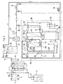
- This installation further includes interposed on the pipe 40, between the activated carbon filter 2 and the softeners 6, 7, a container 3 containing a disinfectant-descaling product capable of being injected into said pipe, by means of a metering pump 4, via a pipe connected to line 40 at by means of a quick coupling.
- This installation also includes a buffer tank 10 in which opens out the downstream end of the pipe 40, said tank being equipped with a level control float valve 10a (or a solenoid valve controlled by high and low levels), and acting as a hydraulic backflow preventer vis-à-vis the public network.
- a level control float valve 10a or a solenoid valve controlled by high and low levels
- a probe 9 capable of measuring the characteristics electrical (conductivity or resistivity) of the filtered raw water is inserted on the line 40, upstream of the buffer tank 10.
- This installation then comprises a main pipe 11 on which is inserted a high pressure pump 12 adapted to distribute water to a constant pressure (10 to 12 bar), controllable by means of a pressure gauge 13, thanks to a classic by-pass system for returning water to the buffer tank (not shown).
- a high pressure pump 12 adapted to distribute water to a constant pressure (10 to 12 bar), controllable by means of a pressure gauge 13, thanks to a classic by-pass system for returning water to the buffer tank (not shown).
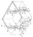
- This main line 11 is adapted to supply all the dialysis stations and extends for this purpose, as shown in Figure 1, around the perimeter of the treatment room, and has a purge or rinse valve 14 at its downstream end (it should be noted that in the figures only 3 dialysis stations ( Figure 1) or 2 dialysis stations ( Figures 2 and 3) have been shown for clarity drawings. It is however obvious that the treatment rooms include usually a much higher number of dialysis stations).
- the installation includes a branch 15 of water distribution to a reverse osmosis cabinet 17 supplying a dialysis generator 18, said branch being connected to the main line 11 by via a quick coupling 16 or a valve.
- Each of the reverse osmosis cabinets 17 integrates, first of all, two small reverse osmosis membranes 19, 25 arranged in series, the water outlet purified 19b of the first membrane 19 being connected to the water inlet 25a of the second membrane 25 by a pipe 23.
- the discharge water outlet 19c from the first membrane 19 is to it, conventionally, connected to the sewer by a line 20 on which is interposed a flow limiter 21, and opening into a disconnection box hydraulic 22.
- the outlet of purified water 25b from the second membrane 25 is to it connected by a flexible hose 28 to a hydraulic connector 31 carried by the dialysis generator 18.
- This hydraulic connector 31 is of the type described in French patent FR 2,704,150, which will be referred to for more details, and comprises therefore, first of all, a rigid body provided with an internal channel arranged to ensure the continuous circulation of purified water from flexible hose 28 to a second flexible hose 33 connected to the reverse osmosis unit 17.
- This hydraulic connector 31 further includes, as described in the aforementioned French patent, a bypass 32 opening into the internal channel and arranged to communicate with the water inlet of the dialysis generator 18.
- the reverse osmosis box 17 also incorporates a bacterial filter 34 and a valve 35 calibrated at a pressure P a of 1 bar determining the supply pressure of the dialysis generator 18 .
- water not used by the dialysis generator 18 and having circulated in the internal channel of the hydraulic connector 31, as well as the discharge water delivered at the rejection outlet 25c of the second membrane 25 and flowing at through a flow limiter 27, are delivered to a recycling pipe 26, suitable for collecting and recycling similar purified water to buffer tank 10 of all dialysis stations.
- Each reverse osmosis unit 17 also includes a pressure gauge 30 arranged downstream of the purified water outlet 25b of the second membrane 25 and adapted to allow the pressure of the purified water leaving said outlet to be controlled second membrane.
- Each of these reverse osmosis cabinets 17 finally comprises three probes 41, 24, 29 disposed respectively upstream of the water inlet 19a of the first membrane 19 and downstream of the purified water outlets 19b, 25b of the first and second membranes 19 and 25, and intended to allow the characteristics to be measured electrical (conductivity or resistivity and rejection rate) of the water leaving said membranes and to inform the nursing staff by any means of indication such as LEDs, liquid crystal displays, beeps.
- each dialysis generator 18 is connected to the hydraulic backflow preventer 22 by a pipeline 36.
- the dialysis facility shown in Figure 3 is similar to that described above, the only difference resulting from the possibilities offered by the design of the installation according to the invention, namely the elimination of the container 3 and of the metering pump 4, as well as softeners 6, 7.
- the product disinfectant-descaler is introduced directly into the buffer tank 10, while the absence of softeners 6, 7, provided that the hardness of the raw water is not too high, is offset by recycling part of the purified water to the buffer tank 10 which leads to lowering the hardness of the water delivered to the membranes 19, 25.
Landscapes
- Health & Medical Sciences (AREA)
- Engineering & Computer Science (AREA)
- Chemical & Material Sciences (AREA)
- Water Supply & Treatment (AREA)
- Urology & Nephrology (AREA)
- Heart & Thoracic Surgery (AREA)
- Chemical Kinetics & Catalysis (AREA)
- Life Sciences & Earth Sciences (AREA)
- Animal Behavior & Ethology (AREA)
- General Health & Medical Sciences (AREA)
- Nanotechnology (AREA)
- Emergency Medicine (AREA)
- Veterinary Medicine (AREA)
- Vascular Medicine (AREA)
- Anesthesiology (AREA)
- Biomedical Technology (AREA)
- Hematology (AREA)
- Public Health (AREA)
- Hydrology & Water Resources (AREA)
- Environmental & Geological Engineering (AREA)
- Organic Chemistry (AREA)
- General Chemical & Material Sciences (AREA)
- External Artificial Organs (AREA)
Applications Claiming Priority (2)
| Application Number | Priority Date | Filing Date | Title |
|---|---|---|---|
| FR0102486A FR2821273B1 (fr) | 2001-02-23 | 2001-02-23 | Installation de dialyse multipostes perfectionnee pour centre ou antenne d'auto-dialyse |
| FR0102486 | 2001-02-23 |
Publications (1)
| Publication Number | Publication Date |
|---|---|
| EP1234590A1 true EP1234590A1 (de) | 2002-08-28 |
Family
ID=8860364
Family Applications (1)
| Application Number | Title | Priority Date | Filing Date |
|---|---|---|---|
| EP02352003A Withdrawn EP1234590A1 (de) | 2001-02-23 | 2002-02-22 | Mehrstationendialyseeinrichtung |
Country Status (2)
| Country | Link |
|---|---|
| EP (1) | EP1234590A1 (de) |
| FR (1) | FR2821273B1 (de) |
Cited By (6)
| Publication number | Priority date | Publication date | Assignee | Title |
|---|---|---|---|---|
| EP1614437A1 (de) * | 2004-07-08 | 2006-01-11 | Peter Taboada, S.l. | System zur Vorbehandlung von Wasser für die Hämodialyse |
| CN102976449A (zh) * | 2012-12-03 | 2013-03-20 | 张翼鹏 | 纯水机 |
| US8425767B2 (en) | 2007-05-25 | 2013-04-23 | Gambro Lundia Ab | Device for connecting to a liquid source |
| CN103183420A (zh) * | 2013-04-25 | 2013-07-03 | 张翼鹏 | 带加热台下式纳滤机 |
| CN105288761A (zh) * | 2011-08-01 | 2016-02-03 | 曼弗雷德·弗尔克尔 | 单站ro装置与血液透析装置的组合系统 |
| DE102019121003A1 (de) * | 2019-08-02 | 2021-02-04 | B.Braun Avitum Ag | Dialyseanlage mit stationären Wasseraufbereitungseinrichtungen |
Citations (5)
| Publication number | Priority date | Publication date | Assignee | Title |
|---|---|---|---|---|
| US4773993A (en) * | 1984-08-31 | 1988-09-27 | Hitachi, Ltd. | Apparatus for purifying and dispensing water with stagnation preventing means |
| US4773991A (en) * | 1987-03-13 | 1988-09-27 | Baxter Travenol Laboratories, Inc. | Water purification system fluid path |
| WO1992003202A2 (en) * | 1990-08-20 | 1992-03-05 | Abbott Laboratories | Medical drug formulation and delivery system |
| FR2704150A1 (fr) | 1993-04-19 | 1994-10-28 | Lopez Fernand | Installation de dialyse perfectionnée et équipements. |
| DE19826432A1 (de) | 1998-06-16 | 1999-12-23 | Walther Medizintechnik Gmbh | Medizinische Dialyse-Vorrichtung |
-
2001
- 2001-02-23 FR FR0102486A patent/FR2821273B1/fr not_active Expired - Fee Related
-
2002
- 2002-02-22 EP EP02352003A patent/EP1234590A1/de not_active Withdrawn
Patent Citations (5)
| Publication number | Priority date | Publication date | Assignee | Title |
|---|---|---|---|---|
| US4773993A (en) * | 1984-08-31 | 1988-09-27 | Hitachi, Ltd. | Apparatus for purifying and dispensing water with stagnation preventing means |
| US4773991A (en) * | 1987-03-13 | 1988-09-27 | Baxter Travenol Laboratories, Inc. | Water purification system fluid path |
| WO1992003202A2 (en) * | 1990-08-20 | 1992-03-05 | Abbott Laboratories | Medical drug formulation and delivery system |
| FR2704150A1 (fr) | 1993-04-19 | 1994-10-28 | Lopez Fernand | Installation de dialyse perfectionnée et équipements. |
| DE19826432A1 (de) | 1998-06-16 | 1999-12-23 | Walther Medizintechnik Gmbh | Medizinische Dialyse-Vorrichtung |
Cited By (7)
| Publication number | Priority date | Publication date | Assignee | Title |
|---|---|---|---|---|
| EP1614437A1 (de) * | 2004-07-08 | 2006-01-11 | Peter Taboada, S.l. | System zur Vorbehandlung von Wasser für die Hämodialyse |
| US8425767B2 (en) | 2007-05-25 | 2013-04-23 | Gambro Lundia Ab | Device for connecting to a liquid source |
| CN105288761A (zh) * | 2011-08-01 | 2016-02-03 | 曼弗雷德·弗尔克尔 | 单站ro装置与血液透析装置的组合系统 |
| CN105288761B (zh) * | 2011-08-01 | 2018-09-18 | 曼弗雷德·弗尔克尔 | 单站ro装置与血液透析装置的组合系统 |
| CN102976449A (zh) * | 2012-12-03 | 2013-03-20 | 张翼鹏 | 纯水机 |
| CN103183420A (zh) * | 2013-04-25 | 2013-07-03 | 张翼鹏 | 带加热台下式纳滤机 |
| DE102019121003A1 (de) * | 2019-08-02 | 2021-02-04 | B.Braun Avitum Ag | Dialyseanlage mit stationären Wasseraufbereitungseinrichtungen |
Also Published As
| Publication number | Publication date |
|---|---|
| FR2821273A1 (fr) | 2002-08-30 |
| FR2821273B1 (fr) | 2004-10-29 |
Similar Documents
| Publication | Publication Date | Title |
|---|---|---|
| EP0462606B1 (de) | Verfahren und Vorrichtung für die Herstellung von sterilen wässrigen Lösungen | |
| AU2012202387B2 (en) | RO (Reverse Osmosis) System | |
| CN104519924B (zh) | 具有热消毒的系统、装置和设备以及热消毒方法 | |
| WO1999055448A1 (en) | Automatic cleaning system for a reverse osmosis unit in a high purity water treatment system | |
| JP5358894B2 (ja) | 浄水装置 | |
| CN204862720U (zh) | 自清洁饮水机 | |
| EP1614437B1 (de) | System zur Vorbehandlung von Wasser für die Hämodialyse | |
| EP1234590A1 (de) | Mehrstationendialyseeinrichtung | |
| JP2018114473A (ja) | 水処理システム | |
| JP2012200640A (ja) | 飲料水供給システム | |
| JP4174753B2 (ja) | 透析システム | |
| JP2012217867A (ja) | 飲料水供給システム | |
| CN202542991U (zh) | 专业管道杀菌净水系统 | |
| CN102515402A (zh) | 专业管道杀菌净水系统 | |
| KR101051597B1 (ko) | 인공신장기용 정수장치 | |
| JP4188276B2 (ja) | 血液透析システムの洗浄・殺菌方法および同システム用洗浄・殺菌装置 | |
| Martin et al. | Design and technical adjustment of a water treatment system: 15 years of experience | |
| JP4332829B2 (ja) | 透析システム | |
| CN201426859Y (zh) | 一种可对血液净化用制水设备进行消毒的高温消毒设备 | |
| JP2018114471A (ja) | 水処理システム | |
| CN107261236A (zh) | 血液净化装置及灭菌方法 | |
| CN113567321A (zh) | 一种净水器长效抗菌性能的检测方法 | |
| CN101844851A (zh) | 可对血液净化用制水设备进行消毒的高温消毒设备 | |
| CN213506385U (zh) | 一种直饮水综合利用系统 | |
| CN214513802U (zh) | 一种无菌水反渗透过滤系统 |
Legal Events
| Date | Code | Title | Description |
|---|---|---|---|
| PUAI | Public reference made under article 153(3) epc to a published international application that has entered the european phase |
Free format text: ORIGINAL CODE: 0009012 |
|
| AK | Designated contracting states |
Kind code of ref document: A1 Designated state(s): AT BE CH CY DE DK ES FI FR GB GR IE IT LI LU MC NL PT SE TR |
|
| AX | Request for extension of the european patent |
Free format text: AL;LT;LV;MK;RO;SI |
|
| 17P | Request for examination filed |
Effective date: 20030131 |
|
| AKX | Designation fees paid |
Designated state(s): AT BE CH CY DE DK ES FI FR GB GR IE IT LI LU MC NL PT SE TR |
|
| GRAP | Despatch of communication of intention to grant a patent |
Free format text: ORIGINAL CODE: EPIDOSNIGR1 |
|
| STAA | Information on the status of an ep patent application or granted ep patent |
Free format text: STATUS: THE APPLICATION IS DEEMED TO BE WITHDRAWN |
|
| 18D | Application deemed to be withdrawn |
Effective date: 20060909 |