EP1234190B1 - Imagerie thermique de la graisse et des muscles - Google Patents
Imagerie thermique de la graisse et des muscles Download PDFInfo
- Publication number
- EP1234190B1 EP1234190B1 EP00977839A EP00977839A EP1234190B1 EP 1234190 B1 EP1234190 B1 EP 1234190B1 EP 00977839 A EP00977839 A EP 00977839A EP 00977839 A EP00977839 A EP 00977839A EP 1234190 B1 EP1234190 B1 EP 1234190B1
- Authority
- EP
- European Patent Office
- Prior art keywords
- echo
- tissue
- difference
- fat
- sequences
- Prior art date
- Legal status (The legal status is an assumption and is not a legal conclusion. Google has not performed a legal analysis and makes no representation as to the accuracy of the status listed.)
- Expired - Lifetime
Links
- 210000003205 muscle Anatomy 0.000 title claims description 19
- 238000001931 thermography Methods 0.000 title description 2
- 238000002595 magnetic resonance imaging Methods 0.000 claims abstract description 27
- XLYOFNOQVPJJNP-UHFFFAOYSA-N water Substances O XLYOFNOQVPJJNP-UHFFFAOYSA-N 0.000 claims abstract description 24
- 238000010438 heat treatment Methods 0.000 claims abstract description 13
- 210000001519 tissue Anatomy 0.000 claims description 100
- 238000002604 ultrasonography Methods 0.000 claims description 15
- 238000001208 nuclear magnetic resonance pulse sequence Methods 0.000 claims description 14
- 230000005284 excitation Effects 0.000 claims description 11
- 230000004044 response Effects 0.000 claims description 8
- 238000002592 echocardiography Methods 0.000 claims description 7
- 238000000034 method Methods 0.000 abstract description 17
- 230000002596 correlated effect Effects 0.000 abstract description 6
- 238000003384 imaging method Methods 0.000 description 16
- 230000005415 magnetization Effects 0.000 description 12
- 230000003068 static effect Effects 0.000 description 7
- 206010028980 Neoplasm Diseases 0.000 description 5
- 230000010363 phase shift Effects 0.000 description 5
- 230000000694 effects Effects 0.000 description 3
- 239000012530 fluid Substances 0.000 description 3
- 238000012285 ultrasound imaging Methods 0.000 description 3
- 238000002679 ablation Methods 0.000 description 2
- 238000003491 array Methods 0.000 description 2
- 230000001427 coherent effect Effects 0.000 description 2
- 230000001276 controlling effect Effects 0.000 description 2
- 238000010586 diagram Methods 0.000 description 2
- 230000005281 excited state Effects 0.000 description 2
- 239000000835 fiber Substances 0.000 description 2
- 239000012528 membrane Substances 0.000 description 2
- 238000012986 modification Methods 0.000 description 2
- 230000004048 modification Effects 0.000 description 2
- 230000003287 optical effect Effects 0.000 description 2
- 238000002360 preparation method Methods 0.000 description 2
- 238000000264 spin echo pulse sequence Methods 0.000 description 2
- 238000001356 surgical procedure Methods 0.000 description 2
- 229920002799 BoPET Polymers 0.000 description 1
- UFHFLCQGNIYNRP-UHFFFAOYSA-N Hydrogen Chemical compound [H][H] UFHFLCQGNIYNRP-UHFFFAOYSA-N 0.000 description 1
- 239000005041 Mylar™ Substances 0.000 description 1
- 230000008901 benefit Effects 0.000 description 1
- 239000008280 blood Substances 0.000 description 1
- 210000004369 blood Anatomy 0.000 description 1
- 210000000746 body region Anatomy 0.000 description 1
- 210000000988 bone and bone Anatomy 0.000 description 1
- 210000000481 breast Anatomy 0.000 description 1
- 230000008859 change Effects 0.000 description 1
- 230000000875 corresponding effect Effects 0.000 description 1
- 230000008878 coupling Effects 0.000 description 1
- 238000010168 coupling process Methods 0.000 description 1
- 238000005859 coupling reaction Methods 0.000 description 1
- 238000009792 diffusion process Methods 0.000 description 1
- 235000013861 fat-free Nutrition 0.000 description 1
- 229910052739 hydrogen Inorganic materials 0.000 description 1
- 239000001257 hydrogen Substances 0.000 description 1
- 230000006698 induction Effects 0.000 description 1
- 239000000463 material Substances 0.000 description 1
- 238000005259 measurement Methods 0.000 description 1
- 238000002324 minimally invasive surgery Methods 0.000 description 1
- 238000012544 monitoring process Methods 0.000 description 1
- 210000002976 pectoralis muscle Anatomy 0.000 description 1
- 239000004033 plastic Substances 0.000 description 1
- 229920003023 plastic Polymers 0.000 description 1
- 239000004800 polyvinyl chloride Substances 0.000 description 1
- 230000008569 process Effects 0.000 description 1
- 238000011084 recovery Methods 0.000 description 1
- 230000035945 sensitivity Effects 0.000 description 1
- 238000009987 spinning Methods 0.000 description 1
- 239000000126 substance Substances 0.000 description 1
- 230000001225 therapeutic effect Effects 0.000 description 1
- 230000007704 transition Effects 0.000 description 1
- 238000012800 visualization Methods 0.000 description 1
Images


Classifications
-
- G—PHYSICS
- G01—MEASURING; TESTING
- G01R—MEASURING ELECTRIC VARIABLES; MEASURING MAGNETIC VARIABLES
- G01R33/00—Arrangements or instruments for measuring magnetic variables
- G01R33/20—Arrangements or instruments for measuring magnetic variables involving magnetic resonance
- G01R33/44—Arrangements or instruments for measuring magnetic variables involving magnetic resonance using nuclear magnetic resonance [NMR]
- G01R33/48—NMR imaging systems
- G01R33/4804—Spatially selective measurement of temperature or pH
-
- A—HUMAN NECESSITIES
- A61—MEDICAL OR VETERINARY SCIENCE; HYGIENE
- A61B—DIAGNOSIS; SURGERY; IDENTIFICATION
- A61B90/00—Instruments, implements or accessories specially adapted for surgery or diagnosis and not covered by any of the groups A61B1/00 - A61B50/00, e.g. for luxation treatment or for protecting wound edges
- A61B90/36—Image-producing devices or illumination devices not otherwise provided for
- A61B90/37—Surgical systems with images on a monitor during operation
- A61B2090/374—NMR or MRI
-
- A—HUMAN NECESSITIES
- A61—MEDICAL OR VETERINARY SCIENCE; HYGIENE
- A61N—ELECTROTHERAPY; MAGNETOTHERAPY; RADIATION THERAPY; ULTRASOUND THERAPY
- A61N7/00—Ultrasound therapy
- A61N7/02—Localised ultrasound hyperthermia
-
- G—PHYSICS
- G01—MEASURING; TESTING
- G01R—MEASURING ELECTRIC VARIABLES; MEASURING MAGNETIC VARIABLES
- G01R33/00—Arrangements or instruments for measuring magnetic variables
- G01R33/20—Arrangements or instruments for measuring magnetic variables involving magnetic resonance
- G01R33/44—Arrangements or instruments for measuring magnetic variables involving magnetic resonance using nuclear magnetic resonance [NMR]
- G01R33/48—NMR imaging systems
- G01R33/4828—Resolving the MR signals of different chemical species, e.g. water-fat imaging
Definitions
- the present invention relates generally to systems and methods for imaging tissue using magnetic resonance imaging, and more particularly to systems and methods for performing thermal-sensitive imaging of both fat and muscle tissue using focused magnetic resonance imaging.
- a piezoelectric transducer located outside the patient's body may be used to focus high intensity acoustic waves, such as ultrasonic waves (acoustic waves with a frequency greater than about twenty kilohertz (20kHz), and more typically between one and five Megahertz (1-5 MHz)), at an internal tissue region of a patient to therapeutically treat the tissue region.
- the ultrasonic waves may be used to ablate a tumor, thereby obviating the need for invasive surgery.
- laser fibers may be introduced into the patient's body from an entry site that are used to guide coherent optical heat sources to an internal tissue region.
- ultrasound imaging systems may be used for imaging, as well as for generating therapeutic ultrasound waves.
- magnetic resonance imaging (or "MRI") may be used instead of ultrasound imaging, as MRI provides excellent quality images of tissue, and is not limited to "windows" that exclude bone or other structures that may interfere with or otherwise limit ultrasound imaging.
- An MRI system may be used to plan a procedure, for example, before surgery or a minimally invasive procedure, such as an ultrasound ablation procedure.
- a patient may initially be scanned in an MRI system to locate a target tissue region and/or to plan a trajectory between an entry point and the tissue region in preparation for a procedure.
- Such preparation may be particularly useful because a tumor may be more visible in an magnetic resonance ("MR") image than using direct examination.
- MR magnetic resonance
- Due to differences in relaxation times of tumorous and other tissue, MRI images may provide a contrast not available using direct visualization, particularly since tumorous tissue may visually appear similar to normal tissue, or the field of view may be obscured, for example, by blood.
- MRI may be used during the procedure, for example, to image the tissue region and/or to guide the trajectory of an external ultrasound beam to a target tissue region being treated, or to guide laser energy.
- an MRI system may be used to monitor the temperature of the tissue region during the procedure, for example, to ensure that only the target tissue region is necrosed during an ablation procedure without damaging surrounding healthy tissue. Generally, this involves using a separate scanning sequence that provides temperature information, in addition, to a scanning sequence that provides tissue information.
- a lower level of energy may be directed towards the target tissue region, generally in a pulsed or oscillating manner to minimize the effect of thermal diffusion.
- a temperature-sensitive magnetic resonance (“MR") pulse sequence may be used to acquire a temperature "map" to ensure that the energy is applied to the target tissue region and not to the surrounding healthy tissue.
- the imaging system may also be used in a separate scan sequence to create an image of the tissue intended to be destroyed, and then the two images may be superimposed upon one another to identify the location of the energy relative to the target tissue region.
- a focal zone of ultrasonic energy emitted by an ultrasound transducer may be moved by mechanically adjusting the position of the transducer relative to the patient's body.
- the focal zone may be moved electronically. e.g., by controlling a phase component and/or relative amplitude of drive signals to the transducer elements, or a combination of mechanical and electronic positioning may be used, as is known in the art.
- U.S. Patent No. 5,711,300 discloses an MRI system that produces a reference phase image and a measurement phase image using a double gradient echo NMR pulse sequence with a short echo time and a a long echo time.
- a temperature map is produced by calculating a phase difference or complex difference of the two phase images.
- MRI systems exploit the property that free unpaired spinning protons in the nucleus of a molecule of a specific tissue, such as hydrogen molecules, align themselves in a magnetic field such that their axes precess about the magnetic field.
- unpaired protons have non-zero "spin" and consequently behave like a small magnetic dipole.
- the net sum of the population of dipoles results in a bulk magnetization vector M that is aligned with a static magnetic field B0, shown in Figure 1 in a reference frame X'Y'Z', and rotating about the static magnetic field axis at a frequency equal to the precession of the spins (the Larmor frequency).
- the magnetic dipoles forming the net magnetization vector M ordinarily are aligned with the applied magnetic field. However, these magnetic dipoles have an excited state that opposes this applied magnetic field. Pulses resulting from an RF excitation at the Larmor frequency will cause the magnetic dipoles to transition from the aligned state to the opposing state.
- An MR imaging device uses a radio frequency (RF) transmitter to "flip" the magnetic dipoles into the excited state by transmitting RF energy at the Larmor frequency. For example, a one hundred eight degree (180°) pulse from the RF transmitter will rotate or "flip" the magnetization vector M down to align along the -Z' axis. This behavior is generic to any orientation of the magnetization vector.
- RF radio frequency
- a magnetic field gradient is applied during the RF excitation pulse. Because of the linear gradient, only spins located in a particular slice or plane through the patient will respond to a given RF pulse.
- Figure 2 illustrates the resulting net magnetization vector M after application of a ninety degree (90°) pulse.
- This vector aligns with the Y' axis and thus is entirely in the transverse X'Y' plane.
- Two time constants, T1 and T2 govern the relaxation of this perturbed or excited magnetic field vector back to the equilibrium state of Figure 1 .
- T1 relates to the time necessary for the decay in the longitudinal component of the excited magnetization vector.
- T2 relates to the time necessary for the decay in the transverse component of the excited magnetization vector. Because two factors contribute to the decay of transverse magnetization, a combined time constant T2* is generally used to represent the two contributions.
- a spin-echo sequence One commonly used pulse sequence in MRI systems is known as a spin-echo sequence.
- a ninety degree (90°) RF pulse is first applied to the spins, as discussed with respect to Figure 2 .
- the transverse magnetic field begins to dephase.
- a one hundred eighty degree (180°) pulse is applied.
- This pulse causes the transverse magnetic field to partially rephase such that a signal is produced called an echo, which is a function of both time constants T1 and T2*.
- other sequences may be used, such as a gradient echo sequence, a gradient refocused echo sequence, as are well known to those skilled in the art.
- the first gradient is applied along one of the sides of the image plane, i.e., conventionally denoted to be on the Y-axis (phase encode axis).
- the second gradient is applied along the remaining edge of the image plane, conventionally denoted to be on the X-axis (readout axis).
- the present invention is directed to a system for imaging tissue using magnetic resonance imaging, and more particularly to a system for performing thermal-sensitive imaging of both fat and muscle tissue using focused magnetic resonance imaging.
- a single RF excitation pulse during each of the two echo sequences may be used to generate the respective pairs of echoes.
- the first echo is compared to the third echo to obtain an indication of the temperature shift representative of fat tissue
- the second echo is compared to the fourth echo to obtain an indication of the temperature shift representative-of water-based tissue.
- a magnitude difference between the third echo and the first echo is measured and correlated to the temperature shift in fat tissue
- a phase difference between the fourth echo and the second echo is measured and correlated to the temperature shift in water-based tissue.
- a thermal image may then be generated of the tissue region based upon the temperature shifts in fat and water-based tissue.
- the third echo and the first echo may be compared to obtain a first difference
- the fourth echo and the second echo may be compared to obtain a second difference.
- a complex difference of the first and second differences may then be combined to facilitate identifying a location of the thermal energy.
- the complex difference may be compared with at least one of the first difference and the second difference to identify whether the location of the thermal energy is within fat tissue or muscle tissue.
- the present invention provides a system that facilitates monitoring a target tissue region, such as tumor, being treated to ensure that the target tissue region is necrosed without damaging surrounding healthy tissue.
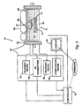
- FIG. 3 shows a schematic block diagram of an MRI-guided ultrasound pulsed heat system 10, in accordance with one aspect of the present invention.
- the system 10 generally includes a focused ultrasound system 11, and a magnetic resonance imaging ("MRI") system 50.
- MRI magnetic resonance imaging
- other systems for delivering thermal energy to a target tissue region may be provided instead of a focused ultrasound system, such as coherent optical heat sources that may be guided by laser fiber, and the like.
- the focused ultrasound system 11 includes a piezoelectric transducer 12, which is preferably mounted within a chamber 32 filled with degassed water or similar acoustically transmitting fluid.
- the chamber 32 may be located within a table 30 upon which a patient 40 may be disposed or within a fluid-filled bag mounted on a movable arm that may be placed against a patient's body (not shown).
- the transducer is coupled to drive circuitry and/or a controller (not shown) for generating and/or controlling the ultrasonic energy emitted by the transducer, as is well known in the art.
- the transducer 12 is a spherical cap transducer array that is divided into a plurality of concentric rings and/or angular sectors (not shown).
- the configuration of the transducer 12, however, is not important to the present invention, and any of a variety of known ultrasound transducers may be used, such as flat circular arrays, linear arrays, and the like.
- a positioning system 34 may be connected to the transducer 12 for mechanically moving the transducer 12 in one or more directions, and preferably in any of three orthogonal directions.
- a focal distance (a distance from the transducer 12 to a focal zone 38 of the ultrasonic energy emitted by the transducer 12) may be electronically adjusted using known methods, or a combination of mechanical and electronic positioning may be used.
- Exemplary transducers and positioning systems are disclosed in co-pending applications Serial Nos. 09/556,095, filed April 21, 2000 , and 09/557,078, filed April 21, 2000 .
- the top of the table 30 generally includes a flexible membrane 36 that is substantially transparent to ultrasound, such as mylar, polyvinyl chloride (PVC), or other suitable plastic material.
- a fluid-filled bag (not shown) may be provided on the membrane 36 that may conform easily to the contours of the patient 40 disposed on the table 30, thereby acoustically coupling the patient 40 to the transducer 12 within the chamber 32.
- the MRI system 50 includes a static field magnet 52, a gradient field amplifier 54, a radio frequency ("RF") transmitter 56, a receiver 58, and a computation unit 60 that may acquire images of the tissue structure 42.
- the magnet 52 includes a region for receiving a patient therein, and provides a static, relatively homogeneous magnetic field B0 over the patient 40, as is well known in the art.
- Gradient field amplifier 54 generates magnetic field gradients that vary the static magnetic field B0 in a known manner, and/or as described further below.
- the RF transmitter 56 generates and transmits the necessary RF pulse sequences over the patient 40 to cause the tissue structure 42 to emit MR response signals, which may include free induction decay (FID) signals and/or echo signals.
- the RF transmitter 56 includes RF coils (not shown) in the magnet 52, and a pulse transmitter (also not shown), which may have a pulse transmitter frequency supplied by a synthesizer and/or may be controlled by a control processor (both also not shown).
- Raw MR response signals may be sensed by the receiver 58, which may include a separate set of RF coils (not shown) from the RF transmitter 50.
- the RF transmitter 56 may be configured to operate alternately in a transmitting mode and then in a receiving mode to receive the MR response signals, for example, by switching the RF coils of the RF transmitter 56 using the control processor.
- the MR response signals may then be passed to the computation unit 60, which may include an analog-to-digital converter and an image processor (both not shown), that computes an MR image.
- the computation unit 60 may then display the MR images on a display 62.
- a controller 64 may be coupled to the MRI system 50 for receiving the MR images from the computation unit 60. The controller 64 may then be used to compute a path from the transducer 12 to the tissue structure 42 and/or control the transducer 12. For example, the controller 64 may actuate the positioning system 34, or otherwise direct the electronics associated with the transducer 12 in order to position the focal zone 38 of the transducer 12 at a desired location, i.e., within the target tissue region 42.
- the MRI system 10 employs real-time temperature-sensitive pulse sequences to rapidly acquire temperature-sensitive images of the patient 40.
- these thermal images may be superimposed on another medical diagnostic image (such as a conventional MR image). Since both the tissue structure 42 and heated regions may be imaged, the operator may accurately position the heated region, i.e., the focal zone 38, to correspond to a desired internal structure and accurately heat the target tissue region 42.
- the MRI system 40 is configured for generating a two echo gradient echo sequence, as shown, that may be used to provide a thermal image of both fat and water-based tissue (i.e., non-fat tissue, such as muscle) using a single RF excitation.
- the system 40 generally combines information from a relatively fast or "short" echo and a relatively long echo to obtain temperature shift data for fat and muscle tissue, respectively.
- the temperature shift data of the fat and muscle tissue may then be combined to provide a thermal image of an imaged tissue region. If desired, the thermal image may then be combined with another tissue image, as explained above.
- a single RF excitation pulse 110 is used to generate both echoes, preferably causing a relatively low-angle flip, e.g., between about ten and ninety degrees (10-90°).
- the preferred flip angle for temperature imaging of water-based tissue, such as muscle is between about twenty to thirty degrees (20-30°), because of the relatively long T1 of water-based tissue (approximately 800 milliseconds (ms)).
- Fat tissue in contrast, has a relatively short T1 (approximately 300 ms), and therefore a higher flip angle, e.g., between about seventy to eighty degrees (70-80°), may be preferred to provide better temperature contrast for fat tissue.
- Such higher flip angles may cause saturation effects in water-based tissue, and therefore flip angles of between about sixty to seventy degrees (60-70°) are most preferred.
- a slice selection gradient 116, 118 is applied with the RF pulse 110, as is well known in the art.
- a phase encoding gradient 120 is then applied next, along with a dephasing frequency encoding gradient 122 so as to cause the spins to be in phase at the center of the acquisition period.
- the dephasing frequency encoding gradient is negative in sign from that of the frequency encoding gradient turned on during the acquisition of the MR response signals. Echoes are produced when the frequency encoding gradient is turned on because this gradient refocuses the dephasing that occurs from the dephasing gradient.
- the first echo 112 may be acquired to provide information attributable to fat tissue.
- the first echo 112 may be assumed to be produced substantially by fat tissue, because of the relatively short T2* of fat tissue, and the relative brightness of MR response signals produced by fat tissue as compared to water-based tissue.
- time TE2 preferably between about ten to twenty milliseconds (10-20 ms)
- the second echo 114 may be attributable to water-based tissue.
- the signal from fat tissue becomes negligible, and the signal from water-based tissue dominates the second echo 114.
- the MRI system 40 may determine the temperature shift or increase resulting from delivering thermal energy within a target tissue region.
- a gradient refocused echo (“GRE") sequence or other known sequences may be used instead of a gradient echo sequence, as will be appreciated by those skilled in the art.
- Gradient echo sequences are preferred, however, because the imaging time using gradient echo sequences is generally faster. This is due to the echo times obtained using gradient echo sequences being substantially shorter as compared to those obtained using spin-echo sequences.
- the magnetization vector M may recover to its equilibrium position along the Z axis more quickly, and therefore allow the imaging sequence to be repeated more rapidly (full recovery being desired before repeating the sequence in order to maximize signal strength).
- Using gradient echo sequences may result in less signal being available, because the magnetization vector M may recover to equilibrium much more rapidly, and therefore signal strength may be traded off in exchange for a gain in imaging time.
- Each echo has a magnitude and a phase that may be represented by a complex number or phasor.
- the second echo 114 which is used to measure the temperature increase in muscle, may thus be represented by IC, the cold complex data (before heating), and by IH, the hot complex data (after heating).
- the temperature shift in muscle may be determined.
- the temperature shift is generally determined empirically, as will be appreciated by those skilled in the art. Within animal tissue, for example, it has been found that the temperature shift is given by about one percent (1%) of the magnitude signal per degree Celsius. Because the fat signal is more intense or "bright" than the muscle signal in the first echo 112 by approximately a factor of two, a magnitude shift method may be used for measuring the temperature shift in fat tissue.
- the magnitude difference between the first respective echoes before and after heating may be correlated to a temperature shift in fat tissue, while the phase difference between the second respective echoes before and after heating may be correlated to a temperature shift in muscle tissue.
- This temperature shift data may then be processed and displayed together to show the temperature contrast of the tissue region being treated.
- the MRI system 40 may measure the magnitude of the complex difference for each echo and combine these difference signals to provide a qualitative indication of the temperature shift, e.g., to identify the focal zone or the region where tissue is being heated, but not necessarily providing an absolute value for the temperature shift.
- the phase difference for fat is substantially zero and does not contribute to this calculation.
- the signal S may then be displayed to identify the location of the region actually being heated, e.g., the focal zone of an ultrasound transducer, as will be appreciated by those skilled in the art.
- the signal S may be compared to the temperature shift data from the first echo to identify whether the focal zone is located within a fat structure or a water-based tissue structure.
- the pulse sequence may be calibrated to give roughly the same signal change for muscle Dm as for fat Df so that a rough estimate of the temperature rise may be derived. If it is known that the area wherein temperature estimates are being derived is substantially all muscle, the phase difference alone may give a more accurate result.
- the receive bandwidth for the first echo may be substantially higher than for the second echo. This results in a pulse sequence that is not much longer in time than previous single echo sequences used for phase shift temperature maps in muscle.
- the bandwidth during reception of the first echo e.g., 16-32kHz
- the chemical shift artifacts from fat may be reduced.
- a lower bandwidth during reception of the second echo may increase the signal-to-noise ratio from the water-based signal.
- fat and water-based tissues have slightly different resonant frequencies that may affect the choice of the RF excitation frequency. Because only one RF excitation pulse is used for both echoes, it is preferred to select the center frequency corresponding to the resonant frequency for water. This choice may have little effect on the first echo time used for fat, because of the relatively short echo time used in the first echo.
Claims (12)
- Système (10) pour imagerie à résonance magnétique thermique, comprenant un système de chauffage (11) pour fournir une énergie thermique à une région de tissus cible à l'intérieur d'un patient, et un système d'imagerie à résonance magnétique (50) comprenant un émetteur (56) de radiofréquence (RF) et un récepteur (58), caractérisé par :le système d'imagerie à résonance magnétique (50) est configuré pour commander l'émetteur RF (56) de manière à ce que des séquences d'impulsions RF génèrent une première séquence de deux échos avant de chauffer la région de tissus cible à l'intérieur du patient, la première séquence de deux échos ayant un premier écho optimisé pour un contraste de température avec des tissus adipeux et un deuxième écho optimisé pour un contraste de température avec des tissus aqueux, et génèrent une deuxième séquence de deux échos après le chauffage de la région de tissus cible à l'intérieur du patient avec l'appareil de chauffage, la deuxième séquence de deux échos ayant un troisième écho optimisé pour un contraste de température avec des tissus adipeux et un quatrième écho optimisé pour un contraste de température avec des tissus aqueux, le récepteur (58) étant configuré pour détecter les séquences d'échos générées par les tissus dans la région de tissus cible à l'intérieur du patient en réponse aux séquences d'impulsions RF qui leur sont appliquées ; etune unité de calcul (60) est couplée au récepteur (58) pour qu'il lui soit passé les première et deuxième séquences de deux échos détectées par le récepteur (58), l'unité de calcul (60) étant configurée pour comparer le premier écho au troisième écho pour obtenir une indication du décalage de température dans des tissus adipeux, et pour comparer le deuxième écho au quatrième écho pour obtenir une indication du décalage de température dans des tissus aqueux.
- Système selon la revendication 1, dans lequel l'unité de calcul (60) est configurée pour mesurer une différence de grandeur entre le troisième écho et le premier écho, et pour corréler la différence de grandeur avec le décalage de température dans des tissus adipeux.
- Système selon la revendication 1 ou 2, dans lequel l'unité de calcul (60) est configurée pour mesurer une différence de phase entre le quatrième écho et le deuxième écho, et pour corréler la différence de phase avec le décalage de température dans des tissus aqueux.
- Système selon l'une quelconque des revendications 1 à 3, comprenant en outre un affichage (62) couplé à l'unité de calcul (60) pour générer une image thermique de la région de tissus sur la base des décalages de température dans les tissus adipeux et aqueux.
- Système selon l'une quelconque des revendications 1 à 4, dans lequel l'émetteur RF (56) est configuré pour émettre des séquences d'impulsions RF comprenant des séquences d'échos de gradients pour générer les premier, deuxième, troisième et quatrième échos.
- Système selon l'une quelconque des revendications 1 à 5, dans lequel l'émetteur RF (56) est configuré pour générer une impulsion d'excitation de radiofréquence (RF) unique pour générer à la fois le premier écho et le deuxième écho.
- Système selon la revendication 6, dans lequel l'impulsion d'excitation RF générée par l'émetteur RF (56) comprend un retournement d'angle faible de moins d'environ quatre-vingt-dix degrés.
- Système selon l'une quelconque des revendications 1 à 7, dans lequel l'appareil de chauffage (11) comprend un système ultrason concentré comprenant un transducteur piézo-électrique (12).
- Système selon l'une quelconque des revendications 1 à 7, dans lequel l'appareil de chauffage comprend un système ultrason concentré (11) configuré pour concentrer de l'énergie ultrasonique vers la région de tissus entre les étapes de génération de la première séquence de deux échos et de la deuxième séquence de deux échos.
- Système selon l'une quelconque des revendications 1 à 9, dans lequel l'unité de calcul (60) est configurée pour comparer le troisième écho et le premier écho pour obtenir une première différence, et pour comparer le quatrième écho et le deuxième écho pour obtenir une deuxième différence, et dans lequel l'unité de calcul (60) est en outre configurée pour combiner une différence complexe entre la première différence et la deuxième différence pour identifier un emplacement de l'énergie thermique.
- Système selon la revendication 10, dans lequel l'unité de calcul (60) est en outre configurée pour comparer la différence complexe à au moins l'une de la première différence et de la deuxième différence pour identifier si l'emplacement de l'énergie thermique est à l'intérieur de tissus adipeux ou de tissus musculaires.
- Système selon l'une quelconque des revendications 1 à 11, dans lequel l'émetteur RF (56) et le récepteur (58) comprennent un seul dispositif configuré pour fonctionner alternativement dans un mode d'émission pour émettre des séquences d'impulsions RF et dans un mode de réception pour recevoir des séquences d'échos générées par des tissus en réponse aux séquences d'impulsions RF.
Applications Claiming Priority (5)
| Application Number | Priority Date | Filing Date | Title |
|---|---|---|---|
| US696624 | 1996-08-14 | ||
| US16812299P | 1999-11-30 | 1999-11-30 | |
| US168122P | 1999-11-30 | ||
| US09/696,624 US6618608B1 (en) | 1999-11-30 | 2000-10-24 | Thermal imaging of fat and muscle using a simultaneous phase and magnitude double echo sequence |
| PCT/IL2000/000777 WO2001040819A1 (fr) | 1999-11-30 | 2000-11-22 | Imagerie thermique de la graisse et des muscles |
Publications (2)
| Publication Number | Publication Date |
|---|---|
| EP1234190A1 EP1234190A1 (fr) | 2002-08-28 |
| EP1234190B1 true EP1234190B1 (fr) | 2008-10-29 |
Family
ID=26863819
Family Applications (1)
| Application Number | Title | Priority Date | Filing Date |
|---|---|---|---|
| EP00977839A Expired - Lifetime EP1234190B1 (fr) | 1999-11-30 | 2000-11-22 | Imagerie thermique de la graisse et des muscles |
Country Status (6)
| Country | Link |
|---|---|
| US (1) | US6618608B1 (fr) |
| EP (1) | EP1234190B1 (fr) |
| AT (1) | ATE412916T1 (fr) |
| AU (1) | AU1546801A (fr) |
| DE (1) | DE60040683D1 (fr) |
| WO (1) | WO2001040819A1 (fr) |
Families Citing this family (50)
| Publication number | Priority date | Publication date | Assignee | Title |
|---|---|---|---|---|
| US8256430B2 (en) | 2001-06-15 | 2012-09-04 | Monteris Medical, Inc. | Hyperthermia treatment and probe therefor |
| US6618620B1 (en) | 2000-11-28 | 2003-09-09 | Txsonics Ltd. | Apparatus for controlling thermal dosing in an thermal treatment system |
| DE10156178A1 (de) * | 2001-11-15 | 2003-06-05 | Philips Intellectual Property | Mammographie-Zusatz für MR-Elastographie |
| US7542793B2 (en) * | 2002-08-22 | 2009-06-02 | Mayo Foundation For Medical Education And Research | MR-guided breast tumor ablation and temperature imaging system |
| US8088067B2 (en) | 2002-12-23 | 2012-01-03 | Insightec Ltd. | Tissue aberration corrections in ultrasound therapy |
| US7611462B2 (en) | 2003-05-22 | 2009-11-03 | Insightec-Image Guided Treatment Ltd. | Acoustic beam forming in phased arrays including large numbers of transducer elements |
| JP4639045B2 (ja) * | 2003-07-11 | 2011-02-23 | 財団法人先端医療振興財団 | 磁気共鳴断層画像法による自己参照型・体動追従型の非侵襲体内温度分布計測方法及びその装置 |
| US20050215882A1 (en) * | 2004-03-23 | 2005-09-29 | The Regents Of The University Of Michigan | Noninvasive method to determine fat content of tissues using MRI |
| EP1745306A1 (fr) * | 2004-04-29 | 2007-01-24 | Koninklijke Philips Electronics N.V. | Systeme d'imagerie par resonance magnetique, procede d'imagerie par resonance magnetique et programme informatique |
| EP1776597A1 (fr) * | 2004-08-02 | 2007-04-25 | Koninklijke Philips Electronics N.V. | Thermometrie irm impliquant la cartographie de phase et support de reference utilise comme reference de phase |
| US8409099B2 (en) | 2004-08-26 | 2013-04-02 | Insightec Ltd. | Focused ultrasound system for surrounding a body tissue mass and treatment method |
| US20060064002A1 (en) * | 2004-09-20 | 2006-03-23 | Grist Thomas M | Method for monitoring thermal heating during magnetic resonance imaging |
| US8801701B2 (en) * | 2005-03-09 | 2014-08-12 | Sunnybrook Health Sciences Centre | Method and apparatus for obtaining quantitative temperature measurements in prostate and other tissue undergoing thermal therapy treatment |
| US7771418B2 (en) * | 2005-03-09 | 2010-08-10 | Sunnybrook Health Sciences Centre | Treatment of diseased tissue using controlled ultrasonic heating |
| US20070016039A1 (en) | 2005-06-21 | 2007-01-18 | Insightec-Image Guided Treatment Ltd. | Controlled, non-linear focused ultrasound treatment |
| CN101313354B (zh) | 2005-11-23 | 2012-02-15 | 因赛泰克有限公司 | 超高密度超声阵列中的分级切换 |
| WO2007087398A2 (fr) * | 2006-01-25 | 2007-08-02 | The Trustees Of Columbia University In The City Of New York | Systèmes et procédés d'obtention d'une image de vaisseau sanguin par imagerie à résonance magnétique thermosensible |
| US20070196282A1 (en) * | 2006-02-21 | 2007-08-23 | Siemens Medical Solutions Usa, Inc. | Medical diagnostic ultrasound with temperature-dependent contrast agents |
| US8235901B2 (en) | 2006-04-26 | 2012-08-07 | Insightec, Ltd. | Focused ultrasound system with far field tail suppression |
| US8792968B2 (en) * | 2006-09-25 | 2014-07-29 | Song Xiao | System and method for health evaluation |
| US20080161784A1 (en) * | 2006-10-26 | 2008-07-03 | Hogan Joseph M | Method and system for remotely controlled MR-guided focused ultrasound ablation |
| DE102007013564B4 (de) * | 2007-03-21 | 2017-11-09 | Siemens Healthcare Gmbh | Verfahren und Vorrichtung zur automatischen Bestimmung von Strahlen schwächenden Objekten mittels einer Magnetresonanzanlage |
| US8478380B2 (en) * | 2007-05-04 | 2013-07-02 | Wisconsin Alumni Research Foundation | Magnetic resonance thermometry in the presence of water and fat |
| US8251908B2 (en) | 2007-10-01 | 2012-08-28 | Insightec Ltd. | Motion compensated image-guided focused ultrasound therapy system |
| US8425424B2 (en) | 2008-11-19 | 2013-04-23 | Inightee Ltd. | Closed-loop clot lysis |
| US8617073B2 (en) | 2009-04-17 | 2013-12-31 | Insightec Ltd. | Focusing ultrasound into the brain through the skull by utilizing both longitudinal and shear waves |
| EP2437852B1 (fr) * | 2009-06-02 | 2017-03-29 | Koninklijke Philips N.V. | Thérapie guidée par imagerie à résonance magnétique (rm) |
| US9623266B2 (en) | 2009-08-04 | 2017-04-18 | Insightec Ltd. | Estimation of alignment parameters in magnetic-resonance-guided ultrasound focusing |
| US8979871B2 (en) | 2009-08-13 | 2015-03-17 | Monteris Medical Corporation | Image-guided therapy of a tissue |
| US9289154B2 (en) | 2009-08-19 | 2016-03-22 | Insightec Ltd. | Techniques for temperature measurement and corrections in long-term magnetic resonance thermometry |
| WO2011024074A2 (fr) | 2009-08-26 | 2011-03-03 | Insightec Ltd. | Transducteur à ultrasons asymétrique en réseau phasé |
| EP2505138A4 (fr) * | 2009-09-29 | 2018-01-24 | Koninklijke Philips N.V. | Procédé de mesure et de représentation de la répartition de température dans un tissu |
| US8661873B2 (en) | 2009-10-14 | 2014-03-04 | Insightec Ltd. | Mapping ultrasound transducers |
| US8368401B2 (en) | 2009-11-10 | 2013-02-05 | Insightec Ltd. | Techniques for correcting measurement artifacts in magnetic resonance thermometry |
| US11027154B2 (en) | 2010-03-09 | 2021-06-08 | Profound Medical Inc. | Ultrasonic therapy applicator and method of determining position of ultrasonic transducers |
| WO2011112249A1 (fr) | 2010-03-09 | 2011-09-15 | Profound Medical Inc. | Contrôleur d'alimentation rf pour système de thérapie par ultrasons |
| US9707413B2 (en) | 2010-03-09 | 2017-07-18 | Profound Medical Inc. | Controllable rotating ultrasound therapy applicator |
| WO2011112251A1 (fr) | 2010-03-09 | 2011-09-15 | Profound Medical Inc. | Circuits de fluides pour la régulation de la température dans un système de thérapie thermique |
| WO2011115664A2 (fr) * | 2010-03-14 | 2011-09-22 | Profound Medical Inc. | Moteur compatible irm et système de positionnement |
| US9852727B2 (en) | 2010-04-28 | 2017-12-26 | Insightec, Ltd. | Multi-segment ultrasound transducers |
| US8932237B2 (en) | 2010-04-28 | 2015-01-13 | Insightec, Ltd. | Efficient ultrasound focusing |
| EP2423700A1 (fr) | 2010-08-30 | 2012-02-29 | Koninklijke Philips Electronics N.V. | Appareil, procédé informatique et produit de programme informatique pour calculer la température conformément aux données de relaxométrie transversale IRM |
| US9981148B2 (en) | 2010-10-22 | 2018-05-29 | Insightec, Ltd. | Adaptive active cooling during focused ultrasound treatment |
| US9078587B2 (en) * | 2011-10-21 | 2015-07-14 | The Regents Of The University Of California | Method and apparatus for photomagnetic imaging |
| WO2015143026A1 (fr) | 2014-03-18 | 2015-09-24 | Monteris Medical Corporation | Thérapie guidée par l'image d'un tissu |
| US9486170B2 (en) | 2014-03-18 | 2016-11-08 | Monteris Medical Corporation | Image-guided therapy of a tissue |
| US10675113B2 (en) | 2014-03-18 | 2020-06-09 | Monteris Medical Corporation | Automated therapy of a three-dimensional tissue region |
| US10327830B2 (en) | 2015-04-01 | 2019-06-25 | Monteris Medical Corporation | Cryotherapy, thermal therapy, temperature modulation therapy, and probe apparatus therefor |
| US10773093B2 (en) * | 2017-05-29 | 2020-09-15 | Elegant Mathematics LLC | Real-time methods for magnetic resonance spectra acquisition, imaging and non-invasive ablation |
| DE102018205075A1 (de) * | 2018-04-04 | 2019-10-10 | Siemens Healthcare Gmbh | Messsignalgewinnung bei spinechobasierter Bildgebung |
Family Cites Families (9)
| Publication number | Priority date | Publication date | Assignee | Title |
|---|---|---|---|---|
| DE3937428A1 (de) * | 1989-11-10 | 1991-05-16 | Philips Patentverwaltung | Kernspintomographieverfahren zur erzeugung getrennter fett- und wasserbilder und anordnung zur durchfuehrung des verfahrens |
| US5307812A (en) * | 1993-03-26 | 1994-05-03 | General Electric Company | Heat surgery system monitored by real-time magnetic resonance profiling |
| US5594336A (en) * | 1995-06-02 | 1997-01-14 | Picker International, Inc. | Three point technique using spin and gradient echoes for water/fat separation |
| US5711300A (en) * | 1995-08-16 | 1998-01-27 | General Electric Company | Real time in vivo measurement of temperature changes with NMR imaging |
| JP3586047B2 (ja) * | 1995-09-13 | 2004-11-10 | 株式会社東芝 | 磁気共鳴診断装置 |
| AU1062397A (en) * | 1995-11-28 | 1997-06-19 | Dornier Medical Systems, Inc. | Method and system for non-invasive temperature mapping of tissue |
| US5633586A (en) * | 1996-02-29 | 1997-05-27 | Siemens Medical Systems, Inc. | Rapid fat- or water-suppressed multislice MR pulse sequence including initial prepulse |
| EP0944841A1 (fr) * | 1997-10-16 | 1999-09-29 | Koninklijke Philips Electronics N.V. | Procede et dispositif permettant de determiner la repartition de temperature dans un objet a l'aide de la resonance magnetique |
| US6377834B1 (en) * | 1999-05-19 | 2002-04-23 | Wisconsin Alumni Research Foundation | Real time in vivo measurement of temperature changes with contrast enhanced NMR imaging |
-
2000
- 2000-10-24 US US09/696,624 patent/US6618608B1/en not_active Expired - Lifetime
- 2000-11-22 AU AU15468/01A patent/AU1546801A/en not_active Abandoned
- 2000-11-22 EP EP00977839A patent/EP1234190B1/fr not_active Expired - Lifetime
- 2000-11-22 WO PCT/IL2000/000777 patent/WO2001040819A1/fr active Application Filing
- 2000-11-22 AT AT00977839T patent/ATE412916T1/de not_active IP Right Cessation
- 2000-11-22 DE DE60040683T patent/DE60040683D1/de not_active Expired - Lifetime
Also Published As
| Publication number | Publication date |
|---|---|
| US6618608B1 (en) | 2003-09-09 |
| WO2001040819A1 (fr) | 2001-06-07 |
| ATE412916T1 (de) | 2008-11-15 |
| DE60040683D1 (de) | 2008-12-11 |
| EP1234190A1 (fr) | 2002-08-28 |
| AU1546801A (en) | 2001-06-12 |
Similar Documents
| Publication | Publication Date | Title |
|---|---|---|
| EP1234190B1 (fr) | Imagerie thermique de la graisse et des muscles | |
| US7542793B2 (en) | MR-guided breast tumor ablation and temperature imaging system | |
| EP0648339B1 (fr) | Appareil de chirurgie thermique assiste par imagerie rmn en temps reel | |
| US4543959A (en) | Diagnosis apparatus and the determination of tissue structure and quality | |
| US7956613B2 (en) | Method for imaging acoustically induced rotary saturation with a magnetic resonance imaging system | |
| US6246895B1 (en) | Imaging of ultrasonic fields with MRI | |
| US6246896B1 (en) | MRI guided ablation system | |
| US20050065429A1 (en) | Method for three plane interleaved acquisition for three dimensional temperature monitoring with MRI | |
| Gellermann et al. | Methods and potentials of magnetic resonance imaging for monitoring radiofrequency hyperthermia in a hybrid system | |
| US6377834B1 (en) | Real time in vivo measurement of temperature changes with contrast enhanced NMR imaging | |
| JP5047537B2 (ja) | 複数の駆動装置を利用する磁気共鳴エラストグラフィ | |
| US8024025B2 (en) | T1-corrected proton resonance frequency shift thermometry | |
| JPH0622937A (ja) | 器具の位置を監視するための磁気共鳴追跡システム | |
| US6768917B1 (en) | Magnetic resonance imaging method and system | |
| McDannold et al. | Temperature monitoring with line scan echo planar spectroscopic imaging | |
| WO2001035825A1 (fr) | Surveillance par resonance magnetique de therapie par voie thermique | |
| JP6289826B2 (ja) | 合成開口mriセンサを有するカテーテル | |
| JP4574781B2 (ja) | 磁気共鳴装置及び温熱治療装置 | |
| JP4125134B2 (ja) | 磁気共鳴アコーストグラフィ | |
| JPH0523317A (ja) | 磁気共鳴イメージング装置 | |
| Wang et al. | An MRI calorimetry technique to measure tissue ultrasound absorption | |
| US20060232272A1 (en) | Imaging apparatus and method | |
| Hynynen et al. | Pre-clinical testing of a phased array ultrasound system for MRI-guided noninvasive surgery of the brain | |
| JP2003290366A (ja) | 治療装置 | |
| JPH10243932A (ja) | 共鳴空間位置検出方法、装置 |
Legal Events
| Date | Code | Title | Description |
|---|---|---|---|
| PUAI | Public reference made under article 153(3) epc to a published international application that has entered the european phase |
Free format text: ORIGINAL CODE: 0009012 |
|
| 17P | Request for examination filed |
Effective date: 20020524 |
|
| AK | Designated contracting states |
Kind code of ref document: A1 Designated state(s): AT BE CH CY DE DK ES FI FR GB GR IE IT LI LU MC NL PT SE TR |
|
| AX | Request for extension of the european patent |
Free format text: AL;LT;LV;MK;RO;SI |
|
| GRAP | Despatch of communication of intention to grant a patent |
Free format text: ORIGINAL CODE: EPIDOSNIGR1 |
|
| GRAS | Grant fee paid |
Free format text: ORIGINAL CODE: EPIDOSNIGR3 |
|
| GRAA | (expected) grant |
Free format text: ORIGINAL CODE: 0009210 |
|
| AK | Designated contracting states |
Kind code of ref document: B1 Designated state(s): AT BE CH CY DE DK ES FI FR GB GR IE IT LI LU MC NL PT SE TR |
|
| REG | Reference to a national code |
Ref country code: GB Ref legal event code: FG4D |
|
| REG | Reference to a national code |
Ref country code: CH Ref legal event code: EP |
|
| REG | Reference to a national code |
Ref country code: IE Ref legal event code: FG4D |
|
| REF | Corresponds to: |
Ref document number: 60040683 Country of ref document: DE Date of ref document: 20081211 Kind code of ref document: P |
|
| NLV1 | Nl: lapsed or annulled due to failure to fulfill the requirements of art. 29p and 29m of the patents act | ||
| PG25 | Lapsed in a contracting state [announced via postgrant information from national office to epo] |
Ref country code: ES Free format text: LAPSE BECAUSE OF FAILURE TO SUBMIT A TRANSLATION OF THE DESCRIPTION OR TO PAY THE FEE WITHIN THE PRESCRIBED TIME-LIMIT Effective date: 20090209 Ref country code: AT Free format text: LAPSE BECAUSE OF FAILURE TO SUBMIT A TRANSLATION OF THE DESCRIPTION OR TO PAY THE FEE WITHIN THE PRESCRIBED TIME-LIMIT Effective date: 20081029 |
|
| PG25 | Lapsed in a contracting state [announced via postgrant information from national office to epo] |
Ref country code: NL Free format text: LAPSE BECAUSE OF FAILURE TO SUBMIT A TRANSLATION OF THE DESCRIPTION OR TO PAY THE FEE WITHIN THE PRESCRIBED TIME-LIMIT Effective date: 20081029 Ref country code: FI Free format text: LAPSE BECAUSE OF FAILURE TO SUBMIT A TRANSLATION OF THE DESCRIPTION OR TO PAY THE FEE WITHIN THE PRESCRIBED TIME-LIMIT Effective date: 20081029 Ref country code: PT Free format text: LAPSE BECAUSE OF FAILURE TO SUBMIT A TRANSLATION OF THE DESCRIPTION OR TO PAY THE FEE WITHIN THE PRESCRIBED TIME-LIMIT Effective date: 20090330 |
|
| PG25 | Lapsed in a contracting state [announced via postgrant information from national office to epo] |
Ref country code: MC Free format text: LAPSE BECAUSE OF NON-PAYMENT OF DUE FEES Effective date: 20081130 |
|
| REG | Reference to a national code |
Ref country code: CH Ref legal event code: PL |
|
| PG25 | Lapsed in a contracting state [announced via postgrant information from national office to epo] |
Ref country code: BE Free format text: LAPSE BECAUSE OF FAILURE TO SUBMIT A TRANSLATION OF THE DESCRIPTION OR TO PAY THE FEE WITHIN THE PRESCRIBED TIME-LIMIT Effective date: 20081029 Ref country code: DK Free format text: LAPSE BECAUSE OF FAILURE TO SUBMIT A TRANSLATION OF THE DESCRIPTION OR TO PAY THE FEE WITHIN THE PRESCRIBED TIME-LIMIT Effective date: 20081029 |
|
| PG25 | Lapsed in a contracting state [announced via postgrant information from national office to epo] |
Ref country code: SE Free format text: LAPSE BECAUSE OF FAILURE TO SUBMIT A TRANSLATION OF THE DESCRIPTION OR TO PAY THE FEE WITHIN THE PRESCRIBED TIME-LIMIT Effective date: 20090129 |
|
| PLBE | No opposition filed within time limit |
Free format text: ORIGINAL CODE: 0009261 |
|
| STAA | Information on the status of an ep patent application or granted ep patent |
Free format text: STATUS: NO OPPOSITION FILED WITHIN TIME LIMIT |
|
| 26N | No opposition filed |
Effective date: 20090730 |
|
| PG25 | Lapsed in a contracting state [announced via postgrant information from national office to epo] |
Ref country code: IE Free format text: LAPSE BECAUSE OF NON-PAYMENT OF DUE FEES Effective date: 20081122 Ref country code: CH Free format text: LAPSE BECAUSE OF NON-PAYMENT OF DUE FEES Effective date: 20081130 Ref country code: LI Free format text: LAPSE BECAUSE OF NON-PAYMENT OF DUE FEES Effective date: 20081130 |
|
| REG | Reference to a national code |
Ref country code: GB Ref legal event code: 732E Free format text: REGISTERED BETWEEN 20100603 AND 20100609 |
|
| PG25 | Lapsed in a contracting state [announced via postgrant information from national office to epo] |
Ref country code: LU Free format text: LAPSE BECAUSE OF NON-PAYMENT OF DUE FEES Effective date: 20081122 Ref country code: CY Free format text: LAPSE BECAUSE OF FAILURE TO SUBMIT A TRANSLATION OF THE DESCRIPTION OR TO PAY THE FEE WITHIN THE PRESCRIBED TIME-LIMIT Effective date: 20081029 |
|
| PG25 | Lapsed in a contracting state [announced via postgrant information from national office to epo] |
Ref country code: TR Free format text: LAPSE BECAUSE OF FAILURE TO SUBMIT A TRANSLATION OF THE DESCRIPTION OR TO PAY THE FEE WITHIN THE PRESCRIBED TIME-LIMIT Effective date: 20081029 |
|
| PG25 | Lapsed in a contracting state [announced via postgrant information from national office to epo] |
Ref country code: GR Free format text: LAPSE BECAUSE OF FAILURE TO SUBMIT A TRANSLATION OF THE DESCRIPTION OR TO PAY THE FEE WITHIN THE PRESCRIBED TIME-LIMIT Effective date: 20090130 |
|
| REG | Reference to a national code |
Ref country code: FR Ref legal event code: TP Ref country code: FR Ref legal event code: CD |
|
| REG | Reference to a national code |
Ref country code: FR Ref legal event code: PLFP Year of fee payment: 16 |
|
| REG | Reference to a national code |
Ref country code: FR Ref legal event code: PLFP Year of fee payment: 17 |
|
| REG | Reference to a national code |
Ref country code: FR Ref legal event code: PLFP Year of fee payment: 18 |
|
| PGFP | Annual fee paid to national office [announced via postgrant information from national office to epo] |
Ref country code: DE Payment date: 20191121 Year of fee payment: 20 |
|
| PGFP | Annual fee paid to national office [announced via postgrant information from national office to epo] |
Ref country code: IT Payment date: 20191128 Year of fee payment: 20 Ref country code: FR Payment date: 20191120 Year of fee payment: 20 |
|
| PGFP | Annual fee paid to national office [announced via postgrant information from national office to epo] |
Ref country code: GB Payment date: 20191120 Year of fee payment: 20 |
|
| REG | Reference to a national code |
Ref country code: DE Ref legal event code: R071 Ref document number: 60040683 Country of ref document: DE |
|
| REG | Reference to a national code |
Ref country code: GB Ref legal event code: PE20 Expiry date: 20201121 |
|
| PG25 | Lapsed in a contracting state [announced via postgrant information from national office to epo] |
Ref country code: GB Free format text: LAPSE BECAUSE OF EXPIRATION OF PROTECTION Effective date: 20201121 |