EP1234141B1 - Reflektor für lichtemittierenden dioden - Google Patents
Reflektor für lichtemittierenden dioden Download PDFInfo
- Publication number
- EP1234141B1 EP1234141B1 EP00977320A EP00977320A EP1234141B1 EP 1234141 B1 EP1234141 B1 EP 1234141B1 EP 00977320 A EP00977320 A EP 00977320A EP 00977320 A EP00977320 A EP 00977320A EP 1234141 B1 EP1234141 B1 EP 1234141B1
- Authority
- EP
- European Patent Office
- Prior art keywords
- cavity
- wall
- reflector according
- light
- reflector
- Prior art date
- Legal status (The legal status is an assumption and is not a legal conclusion. Google has not performed a legal analysis and makes no representation as to the accuracy of the status listed.)
- Expired - Lifetime
Links
- 230000004048 modification Effects 0.000 description 3
- 238000012986 modification Methods 0.000 description 3
- 238000009792 diffusion process Methods 0.000 description 2
- 210000001364 upper extremity Anatomy 0.000 description 2
- 238000007792 addition Methods 0.000 description 1
- 238000003491 array Methods 0.000 description 1
- 239000012141 concentrate Substances 0.000 description 1
- 238000005286 illumination Methods 0.000 description 1
- 238000004519 manufacturing process Methods 0.000 description 1
- XLYOFNOQVPJJNP-UHFFFAOYSA-N water Substances O XLYOFNOQVPJJNP-UHFFFAOYSA-N 0.000 description 1
Images

Classifications
-
- F—MECHANICAL ENGINEERING; LIGHTING; HEATING; WEAPONS; BLASTING
- F21—LIGHTING
- F21S—NON-PORTABLE LIGHTING DEVICES; SYSTEMS THEREOF; VEHICLE LIGHTING DEVICES SPECIALLY ADAPTED FOR VEHICLE EXTERIORS
- F21S8/00—Lighting devices intended for fixed installation
-
- B—PERFORMING OPERATIONS; TRANSPORTING
- B63—SHIPS OR OTHER WATERBORNE VESSELS; RELATED EQUIPMENT
- B63B—SHIPS OR OTHER WATERBORNE VESSELS; EQUIPMENT FOR SHIPPING
- B63B45/00—Arrangements or adaptations of signalling or lighting devices
- B63B45/04—Arrangements or adaptations of signalling or lighting devices the devices being intended to indicate the vessel or parts thereof
-
- B—PERFORMING OPERATIONS; TRANSPORTING
- B64—AIRCRAFT; AVIATION; COSMONAUTICS
- B64D—EQUIPMENT FOR FITTING IN OR TO AIRCRAFT; FLIGHT SUITS; PARACHUTES; ARRANGEMENT OR MOUNTING OF POWER PLANTS OR PROPULSION TRANSMISSIONS IN AIRCRAFT
- B64D47/00—Equipment not otherwise provided for
- B64D47/02—Arrangements or adaptations of signal or lighting devices
- B64D47/06—Arrangements or adaptations of signal or lighting devices for indicating aircraft presence
-
- F—MECHANICAL ENGINEERING; LIGHTING; HEATING; WEAPONS; BLASTING
- F21—LIGHTING
- F21V—FUNCTIONAL FEATURES OR DETAILS OF LIGHTING DEVICES OR SYSTEMS THEREOF; STRUCTURAL COMBINATIONS OF LIGHTING DEVICES WITH OTHER ARTICLES, NOT OTHERWISE PROVIDED FOR
- F21V5/00—Refractors for light sources
- F21V5/04—Refractors for light sources of lens shape
-
- B—PERFORMING OPERATIONS; TRANSPORTING
- B64—AIRCRAFT; AVIATION; COSMONAUTICS
- B64D—EQUIPMENT FOR FITTING IN OR TO AIRCRAFT; FLIGHT SUITS; PARACHUTES; ARRANGEMENT OR MOUNTING OF POWER PLANTS OR PROPULSION TRANSMISSIONS IN AIRCRAFT
- B64D2203/00—Aircraft or airfield lights using LEDs
-
- F—MECHANICAL ENGINEERING; LIGHTING; HEATING; WEAPONS; BLASTING
- F21—LIGHTING
- F21S—NON-PORTABLE LIGHTING DEVICES; SYSTEMS THEREOF; VEHICLE LIGHTING DEVICES SPECIALLY ADAPTED FOR VEHICLE EXTERIORS
- F21S10/00—Lighting devices or systems producing a varying lighting effect
- F21S10/06—Lighting devices or systems producing a varying lighting effect flashing, e.g. with rotating reflector or light source
-
- F—MECHANICAL ENGINEERING; LIGHTING; HEATING; WEAPONS; BLASTING
- F21—LIGHTING
- F21W—INDEXING SCHEME ASSOCIATED WITH SUBCLASSES F21K, F21L, F21S and F21V, RELATING TO USES OR APPLICATIONS OF LIGHTING DEVICES OR SYSTEMS
- F21W2111/00—Use or application of lighting devices or systems for signalling, marking or indicating, not provided for in codes F21W2102/00 – F21W2107/00
-
- F—MECHANICAL ENGINEERING; LIGHTING; HEATING; WEAPONS; BLASTING
- F21—LIGHTING
- F21W—INDEXING SCHEME ASSOCIATED WITH SUBCLASSES F21K, F21L, F21S and F21V, RELATING TO USES OR APPLICATIONS OF LIGHTING DEVICES OR SYSTEMS
- F21W2111/00—Use or application of lighting devices or systems for signalling, marking or indicating, not provided for in codes F21W2102/00 – F21W2107/00
- F21W2111/04—Use or application of lighting devices or systems for signalling, marking or indicating, not provided for in codes F21W2102/00 – F21W2107/00 for waterways
-
- F—MECHANICAL ENGINEERING; LIGHTING; HEATING; WEAPONS; BLASTING
- F21—LIGHTING
- F21W—INDEXING SCHEME ASSOCIATED WITH SUBCLASSES F21K, F21L, F21S and F21V, RELATING TO USES OR APPLICATIONS OF LIGHTING DEVICES OR SYSTEMS
- F21W2111/00—Use or application of lighting devices or systems for signalling, marking or indicating, not provided for in codes F21W2102/00 – F21W2107/00
- F21W2111/06—Use or application of lighting devices or systems for signalling, marking or indicating, not provided for in codes F21W2102/00 – F21W2107/00 for aircraft runways or the like
-
- F—MECHANICAL ENGINEERING; LIGHTING; HEATING; WEAPONS; BLASTING
- F21—LIGHTING
- F21Y—INDEXING SCHEME ASSOCIATED WITH SUBCLASSES F21K, F21L, F21S and F21V, RELATING TO THE FORM OR THE KIND OF THE LIGHT SOURCES OR OF THE COLOUR OF THE LIGHT EMITTED
- F21Y2115/00—Light-generating elements of semiconductor light sources
- F21Y2115/10—Light-emitting diodes [LED]
Definitions
- the invention relates to a reflector for a light emitting diode ("LED"). More particularly, the invention relates to a LED reflector which may be used with an LED array for specific purpose lights, eg navigational lights.
- LED light emitting diode
- LEDs for light displays are well known. Typically, a LED has a low power consumption and high longevity. However, another characteristic of a LED is its low candescence compared to conventional lights and wide angle of light diffusion. This makes LEDs unsuitable without modification for certain application. Consequently, where the particular application of an array of LEDs requires the light beam to be concentrated in a particular direction or plane, reflector devices have been used. These applications are typically in the navigational area where concentrated light beams are desirable for beacons.
- Tanaka discloses an LED array with a reflector. That invention is said to be an LED array having a printed circuit board, a plurality of LED chips disposed linearly on the printed circuit board, each LED chip being capable of radiating a light beam, and a reflection member for reflecting the light beam from the LED chip and to guide the light beam outward of the LED array in the main illumination direction generally parallel to the surface of the board. Consequently, the Tanaka invention is directed to linear arrays of LEDs and reflection of the LED light beam in a direction perpendicular to the LED (ie parallel to the surface of the circuit board upon which the LED chip is mounted).
- Tanaka also discloses other arrangements to redirect and/or concentrate the light beam from a linear LED array.
- US 5,723,868 (Hammond ) describes an array of reflectors which is arranged to approximately match the arrangement of a two-dimensional array of LEDs sach as used in a 2-D bar code scanner. Each reflector has at least one reflecting wall for reflecting light from a respective LED, thus increasing the amount of LED light illuminating the target.
- the JP10143769 discloses a lighting device with a plurality of LED's arranged in a circle, each LED being provided with a reflector. Each reflector having a depth much less than the corresponding LED.
- a reflector for a circular array of LEDs each having a housing and a front portion for emitting a main beam of light
- the reflector comprising a body having an axis said body defining a plurality of cavities extending radially from the axis in which the LEDs may be at least partially located, comprising:
- the reflector wall which substantially surrounds the perimeter of the housing substantially increases the amount of light emerging from the opening of the reflector.
- the space between the at least one wall and the housing defines a gap through which light passes towards the open end of the cavity.
- a gap increases the amount of light which is reflected towards the opening by enabling the reflector to have shape or surface features which are separate from the LED housing and which direct the light to the open end of the cavity.
- the space may be filled with a transparent medium through which light passes towards the open end of the cavity.
- the transparent medium may be any suitable medium.
- it may form a seal to stop water from entering the cavity.
- the LED is fastenable substantially within the cavity so as to maximise the amount of light which is reflected. Where the LED is fastened substantially within the cavity, then preferably it is fastenable at one end of the cavity and preferably at the opposite end to the opening. This allows for greater reflection of light through the opening by providing a greater area of wall to reflect the light.
- the depth of the cavity approximates the depth of the LED so the upper extremity of the LED does not extend significantly from the body. In this way, any divergent light emitting from the upper region of the LED which is incident on the wall will be reflected towards the opening.
- the at least one wall may be extended from the body to define a pair of divergent surfaces.
- These divergent surfaces permit the light emitting from the cavity to extend substantially along one plane but reflects any incident light upon those surfaces in the same direction. This means the light may radiate in substantially one plane but not substantially in another plane. This is particularly desirable in navigational lights for example in the marine environment, where light travelling upward from a beacon is of little use to mariners who are in approximately the same plane as the beacon
- the direction of reflection of the light may be determined by any suitable mechanism. According to one preferred embodiment, the direction of reflection of the light is determined at least in part by the shape of the wall. According to a particularly preferred embodiment, the shape of the wall substantially determines the direction in which the light is reflected. Preferably the wall is substantially concave in shape and preferably it is axially symmetrical. The direction of reflection may also be determined at least in part by features of the surface of the wall.
- the features of the surface of the wall substantially determine the direction of reflection of the light.
- the wall comprises ridges which increase the amount of light reflected towards the open end of the cavity of the reflector.
- the cavity being formed by the body being at least two parts which are connectable together permits easier replacement and location of the LED in the cavity, especially when the depth of the cavity is similar to the depth of the LED so the upper extremity of the LED does not extend from the cavity.
- the complimentary parts are identical so as to minimize the costs of production.
- the complimentary parts preferably have portions of the cavity formed therein so that upon their connection together the cavity is formed.
- the fastener of the LED would also be formed with such connection.
- the slots for the mounting pins of an LED may be formed when two parts are connected.
- a plurality of reflectors according to the present invention are arranged in an array so as to maximize the amount of light emitted.
- the reflectors are arranged in a circular array, and preferably each reflector is arranged so as to have its opening radially positioned in an outward direction. This arrangement is used when the array is used for 360° light applications such as with beacons. Of course, there is no reason why a linear array for other applications could not be adopted.
- the present invention is in the form of a light which comprises a plurality of reflectors according to the present invention and a plurality of LEDs located therein.
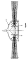
- Figures 1 to 3 illustrate a basic half component 1 of the reflector array 2 of the invention. Two of these components 1 are connected to each other to form reflector array 2 as seen in figure 4.
- Each component 1 has a circular array of half bodies defining half cavities 3.
- Each half body 3 is designed to surround half of the perimeter of the housing in a plane perpendicular to the direction of the main beam each LED (not shown). The wall defining such cavities reflects any incident light towards the opening 5.
- Each cavity 3 has two half passageways 4 extending towards the centre of component 1. These are designed so that when reflector array 2 is formed, the respective half passageways 4 align to form the passageways into which the LED terminals are located and mounted.
- Each component 1 also has a diverging surface 6 extending from the opening 5. As more clearly shown in figure 4, these surfaces 6 will provide additional reflection surfaces of diverging light emanating from the LED in one plane.
- the LED reflector array 2 defines cavities 3.
- a single LED 7 is mounted in each cavity 3 by pressing its terminals 8 into the passageways 4.
- Extending from the wall 5 of each body 3 is a pair of divergent surfaces 6.
- the LED array is mounted on a support 9 which may also support the circuit board (not shown).
- a lens 10 is placed over the LED array 2 to provide a predetermined diffusion/concentration of the light and also to protect the array 2 from the weather.
- the LED array 2 In use, when the LED array 2 is energised, light emits from cavities 3. That light is in turn further directed along a predetermined plane(s) by divergent surfaces 6. Very little light is lost in directions away from the direction of the main beam. As such it is possible to increase the candescence of the beacon.
Landscapes
- Engineering & Computer Science (AREA)
- General Engineering & Computer Science (AREA)
- Chemical & Material Sciences (AREA)
- Combustion & Propulsion (AREA)
- Mechanical Engineering (AREA)
- Ocean & Marine Engineering (AREA)
- Aviation & Aerospace Engineering (AREA)
- Non-Portable Lighting Devices Or Systems Thereof (AREA)
- Led Device Packages (AREA)
- Led Devices (AREA)
- Illuminated Signs And Luminous Advertising (AREA)
Claims (14)
- Ein Reflektor für eine ringförmige Anordnung von Leuchtdioden (LEDs) (2), wobei jede ein Gehäuse und einen vorderen Abschnitt zum Emittieren eines Hauptlichtstrahls aufweist, wobei der Reflektor einen Körper mit einer Achse beinhaltet, wobei der Körper eine Vielzahl von Hohlräumen (3) definiert, die sich radial von der Achse, in der die LEDs (7) zumindest teilweise lokalisiert sein können, erstrecken, der Folgendes beinhaltet:(a) mindestens eine Wand, um im Wesentlichen den Umfang des Gehäuses zu umgeben, wobei die Wand von dem Gehäuse mit Zwischenraum angeordnet ist und angepasst ist, um einfallendes Licht von der LED (7) entlang dem Hohlraum (3) in Richtung eines offenen Endes (5) dieses Hohlraums (3) zu reflektieren; und(b) ein Befestigungselement, um die LED (7) zumindest teilweise in dem Hohlraum (3) zu befestigen,dadurch gekennzeichnet, dass
der Körper mindestens zwei komplementäre ringförmige Teile beinhaltet, die miteinander verbunden werden können. - Reflektor gemäß Anspruch 1, wobei der Raum zwischen der mindestens einen Wand und dem Gehäuse eine Lücke definiert, durch die Licht in Richtung des offenen Endes dieses Hohlraums verläuft.
- Reflektor gemäß Anspruch 1, wobei der Raum zwischen der mindestens einen Wand und dem Gehäuse mit einem optisch klaren Stoff gefüllt ist, durch den Licht in Richtung des offenen Endes dieses Hohlraums verläuft.
- Reflektor gemäß Anspruch 1, wobei die Tiefe des Hohlraums in etwa der Tiefe der LED entspricht.
- Reflektor gemäß Anspruch 1, wobei sich die mindestens eine Wand von dem Körper erstreckt, um ein Paar divergierende Oberflächen zu definieren.
- Reflektor gemäß Anspruch 1, wobei die mindestens eine Wand in der Form im Wesentlichen konkav ist.
- Reflektor gemäß Anspruch 1, wobei die mindestens eine Wand axial symmetrisch ist.
- Reflektor gemäß Anspruch 1, wobei die mindestens eine Wand Rippen beinhaltet, um die Menge an Licht, die in Richtung des offenen Endes dieses Hohlraums reflektiert wird, zu erhöhen.
- Reflektor gemäß Anspruch 1, wobei der Körper identische Teile beinhaltet.
- Reflektor gemäß Anspruch 1, wobei das Befestigungselement durch die Verbindung der komplementären Teile gebildet wird.
- Reflektor gemäß Anspruch 1, wobei die ringförmigen Teile Scheiben beinhalten.
- Reflektor gemäß Anspruch 1, wobei die ringförmigen Teile Ringe beinhalten.
- Reflektor gemäß Anspruch 1, wobei die ringförmigen Teile identisch sind.
- Ein Licht, das eine Vielzahl von Reflektoren gemäß Anspruch 1 und eine Vielzahl von darin lokalisierten LEDs beinhaltet.
Applications Claiming Priority (3)
| Application Number | Priority Date | Filing Date | Title |
|---|---|---|---|
| AUPQ4313A AUPQ431399A0 (en) | 1999-11-29 | 1999-11-29 | Light emitting diode reflector |
| AUPQ431399 | 1999-11-29 | ||
| PCT/AU2000/001432 WO2001040703A1 (en) | 1999-11-29 | 2000-11-24 | Light emitting diode reflector |
Publications (3)
| Publication Number | Publication Date |
|---|---|
| EP1234141A1 EP1234141A1 (de) | 2002-08-28 |
| EP1234141A4 EP1234141A4 (de) | 2006-04-19 |
| EP1234141B1 true EP1234141B1 (de) | 2008-02-06 |
Family
ID=3818455
Family Applications (1)
| Application Number | Title | Priority Date | Filing Date |
|---|---|---|---|
| EP00977320A Expired - Lifetime EP1234141B1 (de) | 1999-11-29 | 2000-11-24 | Reflektor für lichtemittierenden dioden |
Country Status (7)
| Country | Link |
|---|---|
| US (2) | US6667582B1 (de) |
| EP (1) | EP1234141B1 (de) |
| AT (1) | ATE385556T1 (de) |
| AU (2) | AUPQ431399A0 (de) |
| CA (1) | CA2392285C (de) |
| DE (1) | DE60037976D1 (de) |
| WO (1) | WO2001040703A1 (de) |
Families Citing this family (37)
| Publication number | Priority date | Publication date | Assignee | Title |
|---|---|---|---|---|
| AUPQ431399A0 (en) * | 1999-11-29 | 1999-12-23 | Procter, Jeffrey Kenneth | Light emitting diode reflector |
| RU2001125705A (ru) * | 2001-02-23 | 2004-01-10 | Валерий Николаевич Бурцев (UA) | Устройство для демонстрации информации |
| DE10318932A1 (de) * | 2003-04-26 | 2004-11-25 | Aqua Signal Aktiengesellschaft Spezialleuchtenfabrik | Laterne, vorzugsweise für die Verwendung an Bord von Schiffen, insbesondere auf Sportbooten |
| CN100419336C (zh) * | 2003-05-30 | 2008-09-17 | 王伟时 | 环向复合菲乃尔透镜半导体发光二极管信号灯具 |
| US20050146875A1 (en) * | 2004-01-07 | 2005-07-07 | Tideland Signal Corporation | Side-emitting led marine signaling device |
| FR2866693B1 (fr) * | 2004-02-23 | 2010-07-30 | Light Technologies | Dispositif de feux de navigation |
| NL1026276C2 (nl) * | 2004-05-26 | 2005-11-30 | John De Groot | Vaartuig uit inwendig verlicht lichtdoorlatend materiaal. |
| ATE382825T1 (de) * | 2004-06-22 | 2008-01-15 | Klaus Kolb | Laterne zum rundumabstrahlen eines warnsignals |
| DE202004009781U1 (de) * | 2004-06-22 | 2004-09-16 | Kolb, Klaus | Laterne zum Rundumabstrahlen eines Warnsignals |
| US7414546B2 (en) * | 2004-07-08 | 2008-08-19 | Honeywell International Inc. | White anti-collision light utilizing light-emitting diode (LED) technology |
| US20060082999A1 (en) * | 2004-10-18 | 2006-04-20 | Klein W R | Refractive clamp/optic for light emitting diode |
| USD561372S1 (en) * | 2005-05-12 | 2008-02-05 | Weifeng Yan | LED light |
| USD561373S1 (en) * | 2005-05-12 | 2008-02-05 | Weifeng Yan | LED light |
| CN101351891B (zh) | 2005-12-22 | 2014-11-19 | 科锐公司 | 照明装置 |
| JP2009524247A (ja) | 2006-01-20 | 2009-06-25 | クリー エル イー ディー ライティング ソリューションズ インコーポレイテッド | ルミファー膜を空間的に分離することにより固体光発光素子におけるスペクトル内容をシフトすること |
| US8441179B2 (en) | 2006-01-20 | 2013-05-14 | Cree, Inc. | Lighting devices having remote lumiphors that are excited by lumiphor-converted semiconductor excitation sources |
| US20080106430A1 (en) * | 2006-11-02 | 2008-05-08 | Peter Yeh | Modular LED warning lamp |
| EP1927808B1 (de) * | 2006-11-28 | 2009-09-09 | Obelux Oy | Schwachstrom-Flugzeugwarnlampe |
| US20080198572A1 (en) * | 2007-02-21 | 2008-08-21 | Medendorp Nicholas W | LED lighting systems including luminescent layers on remote reflectors |
| CA2695030A1 (en) * | 2009-03-03 | 2010-09-03 | Hella, Inc. | Rotating beacon |
| US8466611B2 (en) | 2009-12-14 | 2013-06-18 | Cree, Inc. | Lighting device with shaped remote phosphor |
| US8705018B2 (en) * | 2010-02-25 | 2014-04-22 | Photoscribe, Inc. | Arrangement for and method of examining gemstones |
| US8651695B2 (en) | 2010-03-26 | 2014-02-18 | Excelitas Technologies Corp. | LED based high-intensity light with secondary diffuser |
| US8393760B2 (en) | 2011-02-07 | 2013-03-12 | Samir Hanna Safar | Fluorescent light emission enhancer light-cone |
| US9223080B2 (en) | 2012-04-24 | 2015-12-29 | Qualcomm Mems Technologies, Inc. | Light guide with narrow angle light output and methods |
| US8979347B2 (en) | 2012-04-24 | 2015-03-17 | Qualcomm Mems Technologies, Inc. | Illumination systems and methods |
| EP2872823B1 (de) | 2012-07-12 | 2017-11-08 | SPX Corporation | Bakenleuchte mit objektiv |
| CA2882858C (en) | 2012-08-22 | 2020-04-28 | Spx Corporation | Light having an omnidirectional ambient light collector |
| CN203892962U (zh) * | 2014-05-28 | 2014-10-22 | 上海开腾信号设备有限公司 | 一种中小直径高光强led环射信号灯 |
| US9881466B2 (en) * | 2015-10-22 | 2018-01-30 | Unimar, Inc. | Annular light system |
| EP3168160B1 (de) * | 2015-11-13 | 2018-07-11 | Goodrich Lighting Systems GmbH | Äussere flugzeugbeleuchtungseinheit und flugzeug damit |
| US10030826B2 (en) * | 2015-12-28 | 2018-07-24 | Federal Signal Corporation | Light beacon lens |
| CN108074359B (zh) * | 2016-11-11 | 2020-12-04 | 西门子瑞士有限公司 | 报警器 |
| US10309595B1 (en) | 2017-07-19 | 2019-06-04 | Star Headlight & Lantern Co., Inc. | LED beacons |
| US10720031B1 (en) | 2018-06-04 | 2020-07-21 | Star Headlight & Lantern Co., Inc. | Warning light beacons |
| AU2020232978A1 (en) * | 2019-03-04 | 2021-09-30 | Sealite Pty Ltd | Sector light and lens |
| CN114275175A (zh) * | 2021-11-25 | 2022-04-05 | 桂林电子科技大学 | 一种景区巡查无人机 |
Family Cites Families (18)
| Publication number | Priority date | Publication date | Assignee | Title |
|---|---|---|---|---|
| US4935665A (en) * | 1987-12-24 | 1990-06-19 | Mitsubishi Cable Industries Ltd. | Light emitting diode lamp |
| DE3929955A1 (de) * | 1989-09-08 | 1991-03-14 | Inotec Gmbh Ges Fuer Innovativ | Lichtstrahler |
| US5130761A (en) | 1990-07-17 | 1992-07-14 | Kabushiki Kaisha Toshiba | Led array with reflector and printed circuit board |
| US5561346A (en) * | 1994-08-10 | 1996-10-01 | Byrne; David J. | LED lamp construction |
| US5608290A (en) * | 1995-01-26 | 1997-03-04 | Dominion Automotive Group, Inc. | LED flashing lantern |
| US5780834A (en) * | 1995-05-15 | 1998-07-14 | Welch Allyn, Inc. | Imaging and illumination optics assembly |
| GB9606695D0 (en) * | 1996-03-29 | 1996-06-05 | Rolls Royce Power Eng | Display sign and an optical element for use with the same |
| JPH103801A (ja) | 1996-06-12 | 1998-01-06 | Seiichi Ohashi | 携帯用合図灯 |
| JP3118503B2 (ja) * | 1996-07-08 | 2000-12-18 | シーシーエス株式会社 | 照明装置 |
| JPH10143769A (ja) * | 1996-11-08 | 1998-05-29 | Keio Teito Electric Railway Co Ltd | 合図灯 |
| US5929788A (en) * | 1997-12-30 | 1999-07-27 | Star Headlight & Lantern Co. | Warning beacon |
| JPH11213729A (ja) | 1998-01-29 | 1999-08-06 | Nikon Corp | 照明装置 |
| US6106137A (en) | 1998-02-20 | 2000-08-22 | Lorin Industries, Inc. | Reflector for automotive exterior lighting |
| US6186649B1 (en) | 1998-04-16 | 2001-02-13 | Honeywell International Inc. | Linear illumination sources and systems |
| US6036336A (en) * | 1998-05-08 | 2000-03-14 | Wu; Chen H. | Light emitting diode retrofitting lamps for illuminated traffic signs |
| DE20000069U1 (de) | 2000-01-04 | 2000-03-30 | Zweibrüder Stahlwarenkontor GmbH, 42697 Solingen | Taschenlampe |
| DE29915504U1 (de) | 1999-09-03 | 2000-01-20 | Zweibrüder Stahlwarenkontor GmbH, 42697 Solingen | Taschenlampe |
| AUPQ431399A0 (en) * | 1999-11-29 | 1999-12-23 | Procter, Jeffrey Kenneth | Light emitting diode reflector |
-
1999
- 1999-11-29 AU AUPQ4313A patent/AUPQ431399A0/en not_active Abandoned
-
2000
- 2000-11-24 EP EP00977320A patent/EP1234141B1/de not_active Expired - Lifetime
- 2000-11-24 DE DE60037976T patent/DE60037976D1/de not_active Expired - Lifetime
- 2000-11-24 AU AU15056/01A patent/AU778918B2/en not_active Ceased
- 2000-11-24 CA CA002392285A patent/CA2392285C/en not_active Expired - Fee Related
- 2000-11-24 US US10/148,362 patent/US6667582B1/en not_active Expired - Lifetime
- 2000-11-24 WO PCT/AU2000/001432 patent/WO2001040703A1/en not_active Ceased
- 2000-11-24 AT AT00977320T patent/ATE385556T1/de not_active IP Right Cessation
-
2003
- 2003-12-19 US US10/741,569 patent/US20040218391A1/en not_active Abandoned
Also Published As
| Publication number | Publication date |
|---|---|
| AUPQ431399A0 (en) | 1999-12-23 |
| AU1505601A (en) | 2001-06-12 |
| EP1234141A1 (de) | 2002-08-28 |
| CA2392285C (en) | 2008-03-04 |
| CA2392285A1 (en) | 2001-06-07 |
| US6667582B1 (en) | 2003-12-23 |
| ATE385556T1 (de) | 2008-02-15 |
| EP1234141A4 (de) | 2006-04-19 |
| WO2001040703A1 (en) | 2001-06-07 |
| DE60037976D1 (de) | 2008-03-20 |
| US20040218391A1 (en) | 2004-11-04 |
| AU778918B2 (en) | 2004-12-23 |
Similar Documents
| Publication | Publication Date | Title |
|---|---|---|
| US6667582B1 (en) | Light emitting diode reflector | |
| AU2020273363B2 (en) | Prismatic LED assembly for luminaire | |
| EP1697685B1 (de) | Leuchtdioden (leds) mit hoher strahlungsleistung verwendende reflektoranordnungen | |
| US7021801B2 (en) | High-intensity directional light | |
| US7246917B2 (en) | Apparatus and method for using emitting diodes (LED) in a side-emitting device | |
| US6637921B2 (en) | Replaceable LED bulb with interchangeable lens optic | |
| KR850000267B1 (ko) | 광학적 엔코우더용 배광장치 | |
| CA2372584C (en) | Aircraft lighting unit using led's | |
| US6623150B2 (en) | Light-emitting diode combination marker/clearance lamp for trucks and trailers | |
| US20020196620A1 (en) | Led flashlight with lens | |
| GB2350176A (en) | A beacon producing light with a wide horizontal angular spread | |
| US7300185B1 (en) | Quadrilateral symmetrical light source | |
| US20060034094A1 (en) | Vehicular marker lamp | |
| EP1453107A4 (de) | Leuchtdiode, led-lampe und lampenvorrichtung | |
| CA2418851A1 (en) | Led flashlight | |
| GB2282877A (en) | A lamp for construction work using a light source having directivity | |
| US8403537B2 (en) | Lighting apparatus | |
| TW201741591A (zh) | 配光透鏡 | |
| CN108074359B (zh) | 报警器 | |
| EP4043782A1 (de) | Optisches element, leuchte und beleuchtungssystem | |
| JP2002100201A (ja) | 工事用保安灯 | |
| CA3096069C (en) | Prismatic led module for luminaire | |
| CN118640436A (zh) | 一种灯具 | |
| JPH04119487U (ja) | 信号表示灯等に用いる光源装置 |
Legal Events
| Date | Code | Title | Description |
|---|---|---|---|
| PUAI | Public reference made under article 153(3) epc to a published international application that has entered the european phase |
Free format text: ORIGINAL CODE: 0009012 |
|
| 17P | Request for examination filed |
Effective date: 20020523 |
|
| AK | Designated contracting states |
Kind code of ref document: A1 Designated state(s): AT BE CH CY DE DK ES FI FR GB GR IE IT LI LU MC NL PT SE TR |
|
| AX | Request for extension of the european patent |
Free format text: AL;LT;LV;MK;RO;SI |
|
| A4 | Supplementary search report drawn up and despatched |
Effective date: 20060302 |
|
| RIC1 | Information provided on ipc code assigned before grant |
Ipc: F21S 8/10 20060101ALI20060227BHEP Ipc: B64D 47/06 20060101ALI20060227BHEP Ipc: F21S 4/00 20060101AFI20010614BHEP Ipc: B63B 45/04 20060101ALI20060227BHEP Ipc: F21Y 101/02 20060101ALI20060227BHEP Ipc: F21W 101/04 20060101ALI20060227BHEP Ipc: F21W 101/06 20060101ALI20060227BHEP |
|
| 17Q | First examination report despatched |
Effective date: 20060919 |
|
| GRAP | Despatch of communication of intention to grant a patent |
Free format text: ORIGINAL CODE: EPIDOSNIGR1 |
|
| GRAS | Grant fee paid |
Free format text: ORIGINAL CODE: EPIDOSNIGR3 |
|
| GRAA | (expected) grant |
Free format text: ORIGINAL CODE: 0009210 |
|
| AK | Designated contracting states |
Kind code of ref document: B1 Designated state(s): AT BE CH CY DE DK ES FI FR GB GR IE IT LI LU MC NL PT SE TR |
|
| REG | Reference to a national code |
Ref country code: GB Ref legal event code: FG4D |
|
| REG | Reference to a national code |
Ref country code: CH Ref legal event code: EP |
|
| REG | Reference to a national code |
Ref country code: IE Ref legal event code: FG4D |
|
| REF | Corresponds to: |
Ref document number: 60037976 Country of ref document: DE Date of ref document: 20080320 Kind code of ref document: P |
|
| PG25 | Lapsed in a contracting state [announced via postgrant information from national office to epo] |
Ref country code: FI Free format text: LAPSE BECAUSE OF FAILURE TO SUBMIT A TRANSLATION OF THE DESCRIPTION OR TO PAY THE FEE WITHIN THE PRESCRIBED TIME-LIMIT Effective date: 20080206 Ref country code: ES Free format text: LAPSE BECAUSE OF FAILURE TO SUBMIT A TRANSLATION OF THE DESCRIPTION OR TO PAY THE FEE WITHIN THE PRESCRIBED TIME-LIMIT Effective date: 20080517 |
|
| NLV1 | Nl: lapsed or annulled due to failure to fulfill the requirements of art. 29p and 29m of the patents act | ||
| PG25 | Lapsed in a contracting state [announced via postgrant information from national office to epo] |
Ref country code: AT Free format text: LAPSE BECAUSE OF FAILURE TO SUBMIT A TRANSLATION OF THE DESCRIPTION OR TO PAY THE FEE WITHIN THE PRESCRIBED TIME-LIMIT Effective date: 20080206 |
|
| PG25 | Lapsed in a contracting state [announced via postgrant information from national office to epo] |
Ref country code: BE Free format text: LAPSE BECAUSE OF FAILURE TO SUBMIT A TRANSLATION OF THE DESCRIPTION OR TO PAY THE FEE WITHIN THE PRESCRIBED TIME-LIMIT Effective date: 20080206 |
|
| PG25 | Lapsed in a contracting state [announced via postgrant information from national office to epo] |
Ref country code: SE Free format text: LAPSE BECAUSE OF FAILURE TO SUBMIT A TRANSLATION OF THE DESCRIPTION OR TO PAY THE FEE WITHIN THE PRESCRIBED TIME-LIMIT Effective date: 20080506 Ref country code: PT Free format text: LAPSE BECAUSE OF FAILURE TO SUBMIT A TRANSLATION OF THE DESCRIPTION OR TO PAY THE FEE WITHIN THE PRESCRIBED TIME-LIMIT Effective date: 20080707 Ref country code: NL Free format text: LAPSE BECAUSE OF FAILURE TO SUBMIT A TRANSLATION OF THE DESCRIPTION OR TO PAY THE FEE WITHIN THE PRESCRIBED TIME-LIMIT Effective date: 20080206 Ref country code: DK Free format text: LAPSE BECAUSE OF FAILURE TO SUBMIT A TRANSLATION OF THE DESCRIPTION OR TO PAY THE FEE WITHIN THE PRESCRIBED TIME-LIMIT Effective date: 20080206 |
|
| EN | Fr: translation not filed | ||
| PLBE | No opposition filed within time limit |
Free format text: ORIGINAL CODE: 0009261 |
|
| STAA | Information on the status of an ep patent application or granted ep patent |
Free format text: STATUS: NO OPPOSITION FILED WITHIN TIME LIMIT |
|
| 26N | No opposition filed |
Effective date: 20081107 |
|
| PG25 | Lapsed in a contracting state [announced via postgrant information from national office to epo] |
Ref country code: DE Free format text: LAPSE BECAUSE OF FAILURE TO SUBMIT A TRANSLATION OF THE DESCRIPTION OR TO PAY THE FEE WITHIN THE PRESCRIBED TIME-LIMIT Effective date: 20080507 |
|
| PG25 | Lapsed in a contracting state [announced via postgrant information from national office to epo] |
Ref country code: FR Free format text: LAPSE BECAUSE OF FAILURE TO SUBMIT A TRANSLATION OF THE DESCRIPTION OR TO PAY THE FEE WITHIN THE PRESCRIBED TIME-LIMIT Effective date: 20081128 |
|
| PG25 | Lapsed in a contracting state [announced via postgrant information from national office to epo] |
Ref country code: MC Free format text: LAPSE BECAUSE OF NON-PAYMENT OF DUE FEES Effective date: 20081130 |
|
| REG | Reference to a national code |
Ref country code: CH Ref legal event code: PL |
|
| PG25 | Lapsed in a contracting state [announced via postgrant information from national office to epo] |
Ref country code: CY Free format text: LAPSE BECAUSE OF FAILURE TO SUBMIT A TRANSLATION OF THE DESCRIPTION OR TO PAY THE FEE WITHIN THE PRESCRIBED TIME-LIMIT Effective date: 20080206 |
|
| PG25 | Lapsed in a contracting state [announced via postgrant information from national office to epo] |
Ref country code: IT Free format text: LAPSE BECAUSE OF FAILURE TO SUBMIT A TRANSLATION OF THE DESCRIPTION OR TO PAY THE FEE WITHIN THE PRESCRIBED TIME-LIMIT Effective date: 20080206 |
|
| PG25 | Lapsed in a contracting state [announced via postgrant information from national office to epo] |
Ref country code: IE Free format text: LAPSE BECAUSE OF NON-PAYMENT OF DUE FEES Effective date: 20081124 Ref country code: LI Free format text: LAPSE BECAUSE OF NON-PAYMENT OF DUE FEES Effective date: 20081130 Ref country code: CH Free format text: LAPSE BECAUSE OF NON-PAYMENT OF DUE FEES Effective date: 20081130 |
|
| PG25 | Lapsed in a contracting state [announced via postgrant information from national office to epo] |
Ref country code: LU Free format text: LAPSE BECAUSE OF NON-PAYMENT OF DUE FEES Effective date: 20081124 |
|
| PG25 | Lapsed in a contracting state [announced via postgrant information from national office to epo] |
Ref country code: TR Free format text: LAPSE BECAUSE OF FAILURE TO SUBMIT A TRANSLATION OF THE DESCRIPTION OR TO PAY THE FEE WITHIN THE PRESCRIBED TIME-LIMIT Effective date: 20080206 |
|
| PG25 | Lapsed in a contracting state [announced via postgrant information from national office to epo] |
Ref country code: GR Free format text: LAPSE BECAUSE OF FAILURE TO SUBMIT A TRANSLATION OF THE DESCRIPTION OR TO PAY THE FEE WITHIN THE PRESCRIBED TIME-LIMIT Effective date: 20080507 |
|
| PGFP | Annual fee paid to national office [announced via postgrant information from national office to epo] |
Ref country code: GB Payment date: 20171127 Year of fee payment: 18 |
|
| GBPC | Gb: european patent ceased through non-payment of renewal fee |
Effective date: 20181124 |
|
| PG25 | Lapsed in a contracting state [announced via postgrant information from national office to epo] |
Ref country code: GB Free format text: LAPSE BECAUSE OF NON-PAYMENT OF DUE FEES Effective date: 20181124 |