EP1233433A2 - Elektromechanisches Schaltgerät - Google Patents
Elektromechanisches Schaltgerät Download PDFInfo
- Publication number
- EP1233433A2 EP1233433A2 EP02001646A EP02001646A EP1233433A2 EP 1233433 A2 EP1233433 A2 EP 1233433A2 EP 02001646 A EP02001646 A EP 02001646A EP 02001646 A EP02001646 A EP 02001646A EP 1233433 A2 EP1233433 A2 EP 1233433A2
- Authority
- EP
- European Patent Office
- Prior art keywords
- spring element
- base
- switching device
- spring
- holding
- Prior art date
- Legal status (The legal status is an assumption and is not a legal conclusion. Google has not performed a legal analysis and makes no representation as to the accuracy of the status listed.)
- Granted
Links
Images

Classifications
-
- H—ELECTRICITY
- H01—ELECTRIC ELEMENTS
- H01H—ELECTRIC SWITCHES; RELAYS; SELECTORS; EMERGENCY PROTECTIVE DEVICES
- H01H1/00—Contacts
- H01H1/12—Contacts characterised by the manner in which co-operating contacts engage
- H01H1/14—Contacts characterised by the manner in which co-operating contacts engage by abutting
- H01H1/20—Bridging contacts
- H01H1/2008—Facilitate mounting or replacing contact bridge and pressure spring on carrier
Definitions
- the invention relates to an electromechanical switching device according to the Preamble of claim 1.
- electromechanical switching devices or clocking line actuators with rotary switches for example used in hobs. Turning the same can switch functions are triggered at certain rotary positions. This happens by either making or breaking electrical contacts between a contact and a counter contact. Contact and Counter contacts can be compressed by spring forces. The electrical is then released against this spring force Contacting or of contact and counter-contact from each other.
- the invention is based on the object, an initially mentioned To create switching device in which the assembly of the spring element is easy, can be done safely and production-friendly.
- the inventive fastening of the spring element on the or against the base by means of trained on the base or contact holder Holding elements has the great advantage that these holding elements already exist before inserting the spring element. An elaborate one This can hold you down during a further assembly step be saved.
- the insertion of a spring element can simple, fast and in a single assembly step or with one single assembly movement.
- a holding element can also be provided on the contact holder.
- Within the scope of the invention is also a combination of interacting holding elements on Base and on the contact holder possible.
- a contact holder can be designed such that an elongated arm carries the contact, preferably a metal arm.
- the arm is in one Plastic body stored or molded.
- the holding elements can be part of another device the base or contact holder and already through its assembly process placed or attached. Preferably for strength reasons becomes a one-piece connection of the holding elements with base or contact holder.
- the holding elements are particularly preferably molded on or during the manufacturing process of the base or contact holder also made with. This has the great advantage that no other Assembly step or additional effort is necessary. When manufacturing of the base or contact holder made of plastic, this can easily be done in the Injection mold are provided.
- the holding elements can preferably resiliently the spring element overlap that when inserting or assembling the spring element give way or dodge its way. When complete inserted spring element you can automatically in their original Go into position or snap and so the spring element against lock a release. In this way, only the usual insertion process is required to be made of the spring element, the holding elements do not have to be operated or pushed away.
- An elongated spring element with spring action is preferred in its Longitudinal direction used.
- a metal coil spring is advantageous.
- the holding elements advantageously run at least partially along the Longitudinal direction or assembly direction of the spring element. Thereby for example, guidance can be effected. Can hold on its end in the inserted state with claw-like or hook-like Reach over or reach behind projections. So a kind Snap lock are formed.
- the projections on the holding elements should be indicative of a spring element to be used Side withdrawn or beveled so that it will take care of itself dodge to insert the spring element. In this way the spring element can also be centered when inserted.
- a movement of the contact holders or the spring travel preferably takes place a spring element essentially straight.
- the contact holder can do this run in a guide device or the like on the base.
- the Guide device can for example as a guide rail or the like. be formed on the outer dimensions of the contact holder or appropriate rails are matched to it.
- At least two or even better four holding elements can be provided. These can either be substantially evenly distributed, for example around the circumference of the spring element. So can for example four holding elements in a cross shape around a coil spring be arranged around as a spring element. In a further embodiment of the Invention can multiple spring elements side by side on a base be arranged for multiple contacts.
- at least one holding element for at least two spring elements be designed. For holding elements with a hook or Projection for holding a spring should either be such a projection be provided per spring to be held. Or is a head start trained to look like two individuals.
- the spring elements can be attached to a base in a grid dimension be evenly distributed, both in a single row and in fields.
- Holding elements are preferred at the cross points of the grid space boundaries arranged, so essentially so that a holding element holds as many spring elements as possible.
- a detent on the contact holder itself a spring element, for example a coil spring, basically secure against losing.
- contact holders are needed and spring element not mounted on the base as separate components to be, but can be pre-assembled as a captive unit become.
- the spring element should be secured to the contact holder do not adversely affect the function or mounting on the base.
- the holding elements or their projections or the like can be designed in this way be that you want the spring element in a precisely defined Hold position. On the one hand, the space inside of holding elements precisely specify this position. Alternatively it is possible by barb-like projections on the holding elements Holding the spring element this due to its restoring force and to position the resulting pressure against the holding elements.
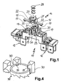
- FIG. 1 shows an oblique view of part of a switchgear base 11.
- the base 11 has metal plug-in lugs projecting downwards 12, which serve as an electrical connection option. With these Plug-in tabs 12 are mating contacts, not shown connected, s. see also Fig. 3, for a switching process with each other get connected.
- This connection is carried out by a contact holder 14, which is electrically conductive, for example made of a resilient metal.
- the contact holder 14 carries on its two continuous arms 15 and 16 each have a contact 17 which bears against the mating contact of the switchgear base 11 is determined.
- the arms 15 and 16 form with the contacts 17 an electrical connection between two mating contacts.
- the contacting takes place in contact chambers 19 what on the one hand for better guidance of arms 15 and 16 and for improvement the electrical insulation properties.
- the contact holder 14 has a central body 21, which is integrally formed Has guide rails 22. These guide rails 22 run in Guide slots 23 of the switchgear base 11. They serve the Contact holder 14 for triggering movements in a predetermined To keep track exactly.
- the central body 21 has a projection 25 on its underside. This projection protrudes through the switching device base 11 into the free intermediate area between the plug connection lugs 12. In this free When the switchgear is fully assembled, the control axis runs along the area differently designed switching cams on which the projection 25th is applied. The projection 25 can be turned upwards by appropriate rotation pressed and the contacts are separated.
- a centering projection 27 is formed between the guide rails 22 or in the middle of the central body 21, a centering projection 27 is formed. About this centering projection 27 engages a coil spring 28 through the centering projection is positioned with its lower end.
- the hooks 31 On the inside of the guide slots 23 or as their limitation elongated holding arms 30 are formed on the inside, at the End inward-facing hooks 31 are attached.
- the coil spring 28 comes between four such holding arms 30 and is thereby the hook 31 overlapping them.
- the distance is the Inner edge of the hooks 31 to each other in the position according to FIG. 1 is smaller than the cross section of the coil spring 28 or these hooks protrude into the cross section.
- the coil spring is shown schematically by a Hollow cylinder 32 shown. It can be seen how the hook 31 the Reach over cylinder 32.
- Spring element can also be a cylindrical elastic body, for example from a foam or plastic.
- FIG. 2 it can be seen how a slipped onto the centering projection 27 Coil spring 28 exactly in the middle of the central body 21 is held.
- the guide rails 22 point to the guide slots 23 to.
- the counter contacts 18 are shown in dashed lines.
- contact holder 14 in the 3 When used in the switchgear base 11 contact holder 14 in the 3 can be seen how the hooks 31 of the holding arms 30 of the switchgear base 11 hold the coil spring 28. This takes place in a position of the contact holder 14 in which the contacts 19th on mating contacts 18 of the switchgear base or the plug connection lugs 12 concerns. This system is due to the spring force of the Coil spring 28 elastic. Will over the projection 25 of the contact holder 14 pushed up to separate contacts 18 and 19, see above this takes place against the elastic resistance of the coil spring 28. A deflection of the same upwards is carried out by the holding arms 30 or whose hook 31 prevented.
- Fig. 4 shows a greatly enlarged version of the holding arms 30. These have claw-like hooks 33 with the claws down point. The claws overlap that represented by the hollow cylinder 32 Coil spring on its inner edge just like it does one Coil spring would overlap. This is compared to normal Even better hold in the form of projections not only achieved against rebounding, but also an exact one Centering the spring. Foam spring elements can insert such claw-like hook 33 into the spring body and secure it this way.
- Fig. 1 it can be seen how the middle are a little wider Holding arms 30 with wide hooks 31 for holding two neighboring ones Coil springs 28 can serve. In this way, the manufacturing effort be greatly reduced. It should be noted that the evasive movement occurring when the helical spring 28 is inserted the holding arms 30 on the beveling of the hook 31 one already held coil spring does not loosen again. This alternative direction namely goes at least partially in the direction of those already held Coil spring so that it does not come loose. Once captured Coil spring is also due to the subsequent assembly other coil springs not loosened again. Specially pointed out is also on the additional function of the holding arms 30 in addition to the bracket as a guide for the contact holder 14 over those running along it Guide rails 22.
- the free space formed between the holding arms can be just as large be like the outside diameter of a spring element.
Landscapes
- Push-Button Switches (AREA)
- Details Of Connecting Devices For Male And Female Coupling (AREA)
- Rotary Switch, Piano Key Switch, And Lever Switch (AREA)
- Breakers (AREA)
Abstract
Description
- Fig. 1
- eine perspektivische Darstellung eines Ausschnitts eines Schaltgerätsockels mit einzusetzendem Kontakthalter sowie Schraubenfeder,
- Fig. 2 und 3
- in Seitenansicht einen zweistufigen Montagevorgang der Bauteile gemäß Fig. 1 und
- Fig. 4
- eine klauenartige Ausführung der Haken.
Claims (10)
- Elektromechanisches Schaltgerät, insbesondere taktender Leistungssteller mit Drehschalter, für ein Elektrogerät, wobei:dadurch gekennzeichnet, dassdas Schaltgerät weist einen Sockel (11) auf,der Sockel trägt wenigstens einen Gegenkontakt (18),ein Kontakthalter (14) ist bewegbar am Sockel aufge nommen,der Kontakthalter trägt wenigstens einen Kontakt (17), der zur wahlweisen Anlage an dem wenigstens einen Gegenkontakt bestimmt ist,ein Federelement (28) ist vorgesehen zum Aufbringen von Kontaktkräften, wobei das Federelement eine Wirkverbindung zwischen dem Sockel und dem Kontakthalter aufweist,das Federelement (28) mittels Halteelementen (30) an dem Sockel (11) gehaltert ist unddie Halteelemente (30) am Sockel (11) oder am Kontakt halter (14) ausgebildet sind.
- Elektromechanisches Schaltgerät nach Anspruch 1, dadurch gekennzeichnet, dass die Halteelemente (30) mit dem Sockel (11) oder dem Kontakthalter (14) einteilig verbunden sind, insbesondere angeformt sind.
- Elektromechanisches Schaltgerät nach Anspruch 1 oder 2, dadurch gekennzeichnet, dass die Halteelemente (30) am Sockel (11) ausgebildet sind.
- Elektromechanisches Schaltgerät nach einem der vorhergehenden Ansprüche, dadurch gekennzeichnet, dass die Halteelemente (30) das Federelement (28) derart elastisch übergreifen, dass beim Einsetzen des Federelementes die Halteelemente nachgeben bzw. ausweichen und bei vollständig eingesetztem Federelement selbsttätig in ihre ursprüngliche Stellung zurückgehen und das Federelement gegen ein Lösen verriegeln.
- Elektromechanisches Schaltgerät nach einem der vorhergehenden Ansprüche, dadurch gekennzeichnet, dass das Federelement (28) länglich ausgebildet ist mit einer Federwirkung in seiner Längsrichtung, wobei es vorzugsweise eine Schraubenfeder ist.
- Elektromechanisches Schaltgerät nach einem der vorhergehenden Ansprüche, dadurch gekennzeichnet, dass die Halteelemente (30) zumindest teilweise entlang der Längsrichtung des Federelementes (28) laufen und dessen Ende mit hakenartigen Vorsprüngen (31) zum Festhalten übergreifen.
- Elektromechanisches Schaltgerät nach einem der vorhergehenden Ansprüche, dadurch gekennzeichnet, dass der Federweg für ein Federelement (28) im wesentlichen geradlinig verläuft, wobei vorzugsweise der Kontakthalter (14) in einer Führungseinrichtung (29) am Sockel (11) läuft und insbesondere die Führungseinrichtung als Führungsschlitze für Führungsschienen (22) am Kontakthalter ausgebildet ist.
- Elektromechanisches Schaltgerät nach einem der vorhergehenden Ansprüche, dadurch gekennzeichnet, dass mindestens zwei, vorzugsweise vier, Halteelemente (30) zum Festhalten eines Federelementes (28) vorgesehen sind.
- Elektromechanisches Schaltgerät nach einem der vorhergehenden Ansprüche, dadurch gekennzeichnet, dass mehrere Federelemente (28) nebeneinander angeordnet sind, wobei wenigstens ein Halteelement (30) für mindestens zwei Federelemente ausgebildet ist, wobei das Halteelement vorzugsweise einen Vorsprung (31) pro zu halterndem Federelement aufweist.
- Elektromechanisches Schaltgerät nach einem der vorhergehenden Ansprüche, dadurch gekennzeichnet, dass die Federelemente (28) in einem Rastermaß gleichmäßig verteilt sind, wobei vorzugsweise Halteelemente (30) an den Kreuzpunkten der Rasterplatzbegrenzungen angeordnet sind.
Applications Claiming Priority (2)
| Application Number | Priority Date | Filing Date | Title |
|---|---|---|---|
| DE2001108960 DE10108960A1 (de) | 2001-02-16 | 2001-02-16 | Elektromechanisches Schaltgerät |
| DE10108960 | 2001-02-16 |
Publications (3)
| Publication Number | Publication Date |
|---|---|
| EP1233433A2 true EP1233433A2 (de) | 2002-08-21 |
| EP1233433A3 EP1233433A3 (de) | 2003-07-09 |
| EP1233433B1 EP1233433B1 (de) | 2007-11-21 |
Family
ID=7675370
Family Applications (1)
| Application Number | Title | Priority Date | Filing Date |
|---|---|---|---|
| EP02001646A Expired - Lifetime EP1233433B1 (de) | 2001-02-16 | 2002-01-24 | Elektromechanisches Schaltgerät |
Country Status (4)
| Country | Link |
|---|---|
| EP (1) | EP1233433B1 (de) |
| DE (2) | DE10108960A1 (de) |
| ES (1) | ES2296833T3 (de) |
| PL (1) | PL197439B1 (de) |
Family Cites Families (9)
| Publication number | Priority date | Publication date | Assignee | Title |
|---|---|---|---|---|
| US4007347A (en) * | 1975-07-28 | 1977-02-08 | Haber Terry M | Simplified actuating switch for electronic timepieces |
| DE2536603C3 (de) * | 1975-08-16 | 1978-12-14 | Preh, Elektrofeinmechanische Werke Jakob Preh Nachf., 8740 Bad Neustadt | Elektrischer Schalter |
| US4345224A (en) * | 1981-01-30 | 1982-08-17 | General Electric Company | Contact spring arrangement |
| IT223977Z2 (it) * | 1990-01-12 | 1995-10-05 | Imos Italia Srl | Zoccolo portacontatti elettrici per accendisigari ed altri accessori di autoveicoli, dotato di protezione termica contro il surriscaldamen-to che ne consente il riutilizzo. |
| DE4439295C1 (de) * | 1994-11-07 | 1996-06-05 | Inovan Stroebe | Kontakthalter |
| DE4446411A1 (de) * | 1994-12-23 | 1996-06-27 | Kopp Heinrich Ag | Vorrichtung zur Beschleunigung des Einschaltvorgangs zwischen elektrischen Kontakten |
| DE29506688U1 (de) * | 1995-04-20 | 1995-06-14 | Priesemuth, Wolfgang, Dipl.-Ing., 83512 Wasserburg | Schalter mit einer Schaltbrücke |
| DE19649816C1 (de) * | 1996-12-02 | 1998-04-23 | Eaton Controls Gmbh | Stößelschalter, insbesondere Bremslichtschalter für Kraftfahrzeuge |
| DE29823559U1 (de) * | 1998-11-09 | 2000-03-30 | Wickmann-Werke GmbH, 58453 Witten | Sicherungshalter |
-
2001
- 2001-02-16 DE DE2001108960 patent/DE10108960A1/de not_active Withdrawn
-
2002
- 2002-01-24 ES ES02001646T patent/ES2296833T3/es not_active Expired - Lifetime
- 2002-01-24 DE DE50211240T patent/DE50211240D1/de not_active Expired - Lifetime
- 2002-01-24 EP EP02001646A patent/EP1233433B1/de not_active Expired - Lifetime
- 2002-02-14 PL PL352242A patent/PL197439B1/pl unknown
Also Published As
| Publication number | Publication date |
|---|---|
| PL197439B1 (pl) | 2008-03-31 |
| DE10108960A1 (de) | 2002-08-29 |
| DE50211240D1 (de) | 2008-01-03 |
| EP1233433B1 (de) | 2007-11-21 |
| ES2296833T3 (es) | 2008-05-01 |
| EP1233433A3 (de) | 2003-07-09 |
Similar Documents
| Publication | Publication Date | Title |
|---|---|---|
| EP2497991A1 (de) | Verbindungsanordnung | |
| DE1172757B (de) | Elektrischer Tuerschalter | |
| WO2016079077A1 (de) | Federkraftklemme | |
| EP0727797A1 (de) | Sicherheitsschalter | |
| DE4117303C2 (de) | Hupenbetätigungseinsatz für ein Lenkrad | |
| DE3827638C2 (de) | ||
| DE2541922B2 (de) | Verriegelbarer Drucktastenschalter | |
| DE102010046752B4 (de) | Schaltelement | |
| EP1764813A1 (de) | Elektrischer Schalter | |
| EP1233433B1 (de) | Elektromechanisches Schaltgerät | |
| CH671651A5 (de) | ||
| DE60006734T2 (de) | Unterbrecher | |
| EP3686908A1 (de) | Elektroinstallationsgerät mit sockelaufsatz | |
| DE3443162A1 (de) | Lenkstockschalter zur fahrtrichtungsanzeige an kraftfahrzeugen | |
| DE2803768C3 (de) | Elektrischer Nockenschalter mit angekuppeltem Drehschalter | |
| EP0017820A1 (de) | Vorrichtung zur Verlängerung von Stösselantrieben | |
| DE3138379C1 (de) | Elektrischer Schalter | |
| DE3001990A1 (de) | Lampenhalter | |
| DE2164652A1 (de) | Elektrischer schalter | |
| CH671482A5 (de) | ||
| DE7538415U (de) | Schaltelement | |
| DE3324253A1 (de) | Tastenschalter | |
| WO1994019210A1 (de) | Lenkstockschalter für kraftfahrzeuge | |
| DE19530241A1 (de) | Schraubenlose Klemme | |
| EP0303159B1 (de) | Abstandhalter für einen elektrischen Kontaktfedersatz |
Legal Events
| Date | Code | Title | Description |
|---|---|---|---|
| PUAI | Public reference made under article 153(3) epc to a published international application that has entered the european phase |
Free format text: ORIGINAL CODE: 0009012 |
|
| AK | Designated contracting states |
Kind code of ref document: A2 Designated state(s): AT BE CH CY DE DK ES FI FR GB GR IE IT LI LU MC NL PT SE TR |
|
| AX | Request for extension of the european patent |
Free format text: AL;LT;LV;MK;RO;SI |
|
| PUAL | Search report despatched |
Free format text: ORIGINAL CODE: 0009013 |
|
| AK | Designated contracting states |
Designated state(s): AT BE CH CY DE DK ES FI FR GB GR IE IT LI LU MC NL PT SE TR |
|
| AX | Request for extension of the european patent |
Extension state: AL LT LV MK RO SI |
|
| 17P | Request for examination filed |
Effective date: 20030723 |
|
| AKX | Designation fees paid |
Designated state(s): AT BE CH CY DE DK ES FI FR GB GR IE IT LI LU MC NL PT SE TR |
|
| GRAP | Despatch of communication of intention to grant a patent |
Free format text: ORIGINAL CODE: EPIDOSNIGR1 |
|
| GRAS | Grant fee paid |
Free format text: ORIGINAL CODE: EPIDOSNIGR3 |
|
| GRAA | (expected) grant |
Free format text: ORIGINAL CODE: 0009210 |
|
| AK | Designated contracting states |
Kind code of ref document: B1 Designated state(s): AT BE CH CY DE DK ES FI FR GB GR IE IT LI LU MC NL PT SE TR |
|
| REG | Reference to a national code |
Ref country code: GB Ref legal event code: FG4D Free format text: NOT ENGLISH |
|
| REG | Reference to a national code |
Ref country code: IE Ref legal event code: FG4D Free format text: LANGUAGE OF EP DOCUMENT: GERMAN |
|
| REG | Reference to a national code |
Ref country code: CH Ref legal event code: EP |
|
| GBT | Gb: translation of ep patent filed (gb section 77(6)(a)/1977) |
Effective date: 20071212 |
|
| REF | Corresponds to: |
Ref document number: 50211240 Country of ref document: DE Date of ref document: 20080103 Kind code of ref document: P |
|
| REG | Reference to a national code |
Ref country code: SE Ref legal event code: TRGR |
|
| PG25 | Lapsed in a contracting state [announced via postgrant information from national office to epo] |
Ref country code: NL Free format text: LAPSE BECAUSE OF FAILURE TO SUBMIT A TRANSLATION OF THE DESCRIPTION OR TO PAY THE FEE WITHIN THE PRESCRIBED TIME-LIMIT Effective date: 20071121 |
|
| NLV1 | Nl: lapsed or annulled due to failure to fulfill the requirements of art. 29p and 29m of the patents act | ||
| REG | Reference to a national code |
Ref country code: ES Ref legal event code: FG2A Ref document number: 2296833 Country of ref document: ES Kind code of ref document: T3 |
|
| PG25 | Lapsed in a contracting state [announced via postgrant information from national office to epo] |
Ref country code: FI Free format text: LAPSE BECAUSE OF FAILURE TO SUBMIT A TRANSLATION OF THE DESCRIPTION OR TO PAY THE FEE WITHIN THE PRESCRIBED TIME-LIMIT Effective date: 20071121 |
|
| BERE | Be: lapsed |
Owner name: E.G.O. ELEKTRO-GERATEBAU G.M.B.H. Effective date: 20080131 |
|
| PG25 | Lapsed in a contracting state [announced via postgrant information from national office to epo] |
Ref country code: DK Free format text: LAPSE BECAUSE OF FAILURE TO SUBMIT A TRANSLATION OF THE DESCRIPTION OR TO PAY THE FEE WITHIN THE PRESCRIBED TIME-LIMIT Effective date: 20071121 |
|
| ET | Fr: translation filed | ||
| PG25 | Lapsed in a contracting state [announced via postgrant information from national office to epo] |
Ref country code: MC Free format text: LAPSE BECAUSE OF NON-PAYMENT OF DUE FEES Effective date: 20080131 |
|
| REG | Reference to a national code |
Ref country code: CH Ref legal event code: PL |
|
| PLBE | No opposition filed within time limit |
Free format text: ORIGINAL CODE: 0009261 |
|
| STAA | Information on the status of an ep patent application or granted ep patent |
Free format text: STATUS: NO OPPOSITION FILED WITHIN TIME LIMIT |
|
| PG25 | Lapsed in a contracting state [announced via postgrant information from national office to epo] |
Ref country code: PT Free format text: LAPSE BECAUSE OF FAILURE TO SUBMIT A TRANSLATION OF THE DESCRIPTION OR TO PAY THE FEE WITHIN THE PRESCRIBED TIME-LIMIT Effective date: 20080421 |
|
| REG | Reference to a national code |
Ref country code: IE Ref legal event code: FD4D |
|
| 26N | No opposition filed |
Effective date: 20080822 |
|
| PG25 | Lapsed in a contracting state [announced via postgrant information from national office to epo] |
Ref country code: LI Free format text: LAPSE BECAUSE OF NON-PAYMENT OF DUE FEES Effective date: 20080131 Ref country code: IE Free format text: LAPSE BECAUSE OF FAILURE TO SUBMIT A TRANSLATION OF THE DESCRIPTION OR TO PAY THE FEE WITHIN THE PRESCRIBED TIME-LIMIT Effective date: 20071121 Ref country code: CH Free format text: LAPSE BECAUSE OF NON-PAYMENT OF DUE FEES Effective date: 20080131 |
|
| PG25 | Lapsed in a contracting state [announced via postgrant information from national office to epo] |
Ref country code: GR Free format text: LAPSE BECAUSE OF FAILURE TO SUBMIT A TRANSLATION OF THE DESCRIPTION OR TO PAY THE FEE WITHIN THE PRESCRIBED TIME-LIMIT Effective date: 20080222 |
|
| PG25 | Lapsed in a contracting state [announced via postgrant information from national office to epo] |
Ref country code: BE Free format text: LAPSE BECAUSE OF NON-PAYMENT OF DUE FEES Effective date: 20080131 |
|
| PG25 | Lapsed in a contracting state [announced via postgrant information from national office to epo] |
Ref country code: AT Free format text: LAPSE BECAUSE OF NON-PAYMENT OF DUE FEES Effective date: 20080124 |
|
| PG25 | Lapsed in a contracting state [announced via postgrant information from national office to epo] |
Ref country code: CY Free format text: LAPSE BECAUSE OF FAILURE TO SUBMIT A TRANSLATION OF THE DESCRIPTION OR TO PAY THE FEE WITHIN THE PRESCRIBED TIME-LIMIT Effective date: 20071121 |
|
| PG25 | Lapsed in a contracting state [announced via postgrant information from national office to epo] |
Ref country code: LU Free format text: LAPSE BECAUSE OF NON-PAYMENT OF DUE FEES Effective date: 20080124 |
|
| PGFP | Annual fee paid to national office [announced via postgrant information from national office to epo] |
Ref country code: FR Payment date: 20120201 Year of fee payment: 11 |
|
| PGFP | Annual fee paid to national office [announced via postgrant information from national office to epo] |
Ref country code: TR Payment date: 20120124 Year of fee payment: 11 |
|
| PGFP | Annual fee paid to national office [announced via postgrant information from national office to epo] |
Ref country code: GB Payment date: 20120124 Year of fee payment: 11 Ref country code: IT Payment date: 20120126 Year of fee payment: 11 Ref country code: SE Payment date: 20120124 Year of fee payment: 11 |
|
| PGFP | Annual fee paid to national office [announced via postgrant information from national office to epo] |
Ref country code: DE Payment date: 20120124 Year of fee payment: 11 |
|
| PGFP | Annual fee paid to national office [announced via postgrant information from national office to epo] |
Ref country code: ES Payment date: 20120124 Year of fee payment: 11 |
|
| REG | Reference to a national code |
Ref country code: SE Ref legal event code: EUG |
|
| GBPC | Gb: european patent ceased through non-payment of renewal fee |
Effective date: 20130124 |
|
| REG | Reference to a national code |
Ref country code: FR Ref legal event code: ST Effective date: 20130930 |
|
| PG25 | Lapsed in a contracting state [announced via postgrant information from national office to epo] |
Ref country code: DE Free format text: LAPSE BECAUSE OF NON-PAYMENT OF DUE FEES Effective date: 20130801 Ref country code: SE Free format text: LAPSE BECAUSE OF NON-PAYMENT OF DUE FEES Effective date: 20130125 |
|
| REG | Reference to a national code |
Ref country code: DE Ref legal event code: R119 Ref document number: 50211240 Country of ref document: DE Effective date: 20130801 |
|
| PG25 | Lapsed in a contracting state [announced via postgrant information from national office to epo] |
Ref country code: FR Free format text: LAPSE BECAUSE OF NON-PAYMENT OF DUE FEES Effective date: 20130131 Ref country code: GB Free format text: LAPSE BECAUSE OF NON-PAYMENT OF DUE FEES Effective date: 20130124 |
|
| PG25 | Lapsed in a contracting state [announced via postgrant information from national office to epo] |
Ref country code: IT Free format text: LAPSE BECAUSE OF NON-PAYMENT OF DUE FEES Effective date: 20130124 |
|
| PG25 | Lapsed in a contracting state [announced via postgrant information from national office to epo] |
Ref country code: TR Free format text: LAPSE BECAUSE OF NON-PAYMENT OF DUE FEES Effective date: 20130124 |
|
| REG | Reference to a national code |
Ref country code: ES Ref legal event code: FD2A Effective date: 20140509 |
|
| PG25 | Lapsed in a contracting state [announced via postgrant information from national office to epo] |
Ref country code: ES Free format text: LAPSE BECAUSE OF NON-PAYMENT OF DUE FEES Effective date: 20130125 |