EP1233287B1 - Dispersionsverschobene Faser - Google Patents
Dispersionsverschobene Faser Download PDFInfo
- Publication number
- EP1233287B1 EP1233287B1 EP02008187A EP02008187A EP1233287B1 EP 1233287 B1 EP1233287 B1 EP 1233287B1 EP 02008187 A EP02008187 A EP 02008187A EP 02008187 A EP02008187 A EP 02008187A EP 1233287 B1 EP1233287 B1 EP 1233287B1
- Authority
- EP
- European Patent Office
- Prior art keywords
- refractive index
- dispersion
- core
- cladding
- wavelength
- Prior art date
- Legal status (The legal status is an assumption and is not a legal conclusion. Google has not performed a legal analysis and makes no representation as to the accuracy of the status listed.)
- Expired - Lifetime
Links
- 239000000835 fiber Substances 0.000 title claims description 85
- 238000005253 cladding Methods 0.000 claims description 126
- 239000006185 dispersion Substances 0.000 claims description 48
- 230000005540 biological transmission Effects 0.000 claims description 32
- 238000005452 bending Methods 0.000 claims description 30
- 230000003287 optical effect Effects 0.000 description 23
- 230000000994 depressogenic effect Effects 0.000 description 19
- 239000013307 optical fiber Substances 0.000 description 12
- 230000014509 gene expression Effects 0.000 description 5
- 238000004891 communication Methods 0.000 description 4
- 230000000694 effects Effects 0.000 description 4
- 239000012792 core layer Substances 0.000 description 3
- 239000010410 layer Substances 0.000 description 3
- 239000000463 material Substances 0.000 description 2
- 229920006395 saturated elastomer Polymers 0.000 description 2
- VYPSYNLAJGMNEJ-UHFFFAOYSA-N Silicium dioxide Chemical compound O=[Si]=O VYPSYNLAJGMNEJ-UHFFFAOYSA-N 0.000 description 1
- 230000001668 ameliorated effect Effects 0.000 description 1
- 230000003247 decreasing effect Effects 0.000 description 1
- 230000005684 electric field Effects 0.000 description 1
- 239000011521 glass Substances 0.000 description 1
- 238000005259 measurement Methods 0.000 description 1
- 238000000034 method Methods 0.000 description 1
- 239000000203 mixture Substances 0.000 description 1
- 238000012986 modification Methods 0.000 description 1
- 230000004048 modification Effects 0.000 description 1
- 238000012545 processing Methods 0.000 description 1
- 230000000644 propagated effect Effects 0.000 description 1
- 230000001902 propagating effect Effects 0.000 description 1
- 230000001603 reducing effect Effects 0.000 description 1
- 238000004904 shortening Methods 0.000 description 1
Images


Classifications
-
- G—PHYSICS
- G02—OPTICS
- G02B—OPTICAL ELEMENTS, SYSTEMS OR APPARATUS
- G02B6/00—Light guides; Structural details of arrangements comprising light guides and other optical elements, e.g. couplings
- G02B6/02—Optical fibres with cladding with or without a coating
- G02B6/02004—Optical fibres with cladding with or without a coating characterised by the core effective area or mode field radius
- G02B6/02009—Large effective area or mode field radius, e.g. to reduce nonlinear effects in single mode fibres
- G02B6/02014—Effective area greater than 60 square microns in the C band, i.e. 1530-1565 nm
-
- C—CHEMISTRY; METALLURGY
- C03—GLASS; MINERAL OR SLAG WOOL
- C03B—MANUFACTURE, SHAPING, OR SUPPLEMENTARY PROCESSES
- C03B37/00—Manufacture or treatment of flakes, fibres, or filaments from softened glass, minerals, or slags
- C03B37/01—Manufacture of glass fibres or filaments
- C03B37/012—Manufacture of preforms for drawing fibres or filaments
- C03B37/014—Manufacture of preforms for drawing fibres or filaments made entirely or partially by chemical means, e.g. vapour phase deposition of bulk porous glass either by outside vapour deposition [OVD], or by outside vapour phase oxidation [OVPO] or by vapour axial deposition [VAD]
- C03B37/01446—Thermal after-treatment of preforms, e.g. dehydrating, consolidating, sintering
-
- C—CHEMISTRY; METALLURGY
- C03—GLASS; MINERAL OR SLAG WOOL
- C03B—MANUFACTURE, SHAPING, OR SUPPLEMENTARY PROCESSES
- C03B37/00—Manufacture or treatment of flakes, fibres, or filaments from softened glass, minerals, or slags
- C03B37/01—Manufacture of glass fibres or filaments
- C03B37/012—Manufacture of preforms for drawing fibres or filaments
- C03B37/014—Manufacture of preforms for drawing fibres or filaments made entirely or partially by chemical means, e.g. vapour phase deposition of bulk porous glass either by outside vapour deposition [OVD], or by outside vapour phase oxidation [OVPO] or by vapour axial deposition [VAD]
- C03B37/01466—Means for changing or stabilising the diameter or form of tubes or rods
-
- G—PHYSICS
- G02—OPTICS
- G02B—OPTICAL ELEMENTS, SYSTEMS OR APPARATUS
- G02B6/00—Light guides; Structural details of arrangements comprising light guides and other optical elements, e.g. couplings
- G02B6/02—Optical fibres with cladding with or without a coating
- G02B6/02214—Optical fibres with cladding with or without a coating tailored to obtain the desired dispersion, e.g. dispersion shifted, dispersion flattened
- G02B6/02219—Characterised by the wavelength dispersion properties in the silica low loss window around 1550 nm, i.e. S, C, L and U bands from 1460-1675 nm
- G02B6/02228—Dispersion flattened fibres, i.e. having a low dispersion variation over an extended wavelength range
- G02B6/02238—Low dispersion slope fibres
-
- G—PHYSICS
- G02—OPTICS
- G02B—OPTICAL ELEMENTS, SYSTEMS OR APPARATUS
- G02B6/00—Light guides; Structural details of arrangements comprising light guides and other optical elements, e.g. couplings
- G02B6/02—Optical fibres with cladding with or without a coating
- G02B6/02214—Optical fibres with cladding with or without a coating tailored to obtain the desired dispersion, e.g. dispersion shifted, dispersion flattened
- G02B6/02219—Characterised by the wavelength dispersion properties in the silica low loss window around 1550 nm, i.e. S, C, L and U bands from 1460-1675 nm
- G02B6/02266—Positive dispersion fibres at 1550 nm
- G02B6/02271—Non-zero dispersion shifted fibres, i.e. having a small positive dispersion at 1550 nm, e.g. ITU-T G.655 dispersion between 1.0 to 10 ps/nm.km for avoiding nonlinear effects
-
- G—PHYSICS
- G02—OPTICS
- G02B—OPTICAL ELEMENTS, SYSTEMS OR APPARATUS
- G02B6/00—Light guides; Structural details of arrangements comprising light guides and other optical elements, e.g. couplings
- G02B6/02—Optical fibres with cladding with or without a coating
- G02B6/02214—Optical fibres with cladding with or without a coating tailored to obtain the desired dispersion, e.g. dispersion shifted, dispersion flattened
- G02B6/0228—Characterised by the wavelength dispersion slope properties around 1550 nm
-
- G—PHYSICS
- G02—OPTICS
- G02B—OPTICAL ELEMENTS, SYSTEMS OR APPARATUS
- G02B6/00—Light guides; Structural details of arrangements comprising light guides and other optical elements, e.g. couplings
- G02B6/02—Optical fibres with cladding with or without a coating
- G02B6/036—Optical fibres with cladding with or without a coating core or cladding comprising multiple layers
- G02B6/03616—Optical fibres characterised both by the number of different refractive index layers around the central core segment, i.e. around the innermost high index core layer, and their relative refractive index difference
- G02B6/03638—Optical fibres characterised both by the number of different refractive index layers around the central core segment, i.e. around the innermost high index core layer, and their relative refractive index difference having 3 layers only
- G02B6/0365—Optical fibres characterised both by the number of different refractive index layers around the central core segment, i.e. around the innermost high index core layer, and their relative refractive index difference having 3 layers only arranged - - +
-
- G—PHYSICS
- G02—OPTICS
- G02B—OPTICAL ELEMENTS, SYSTEMS OR APPARATUS
- G02B6/00—Light guides; Structural details of arrangements comprising light guides and other optical elements, e.g. couplings
- G02B6/02—Optical fibres with cladding with or without a coating
- G02B6/036—Optical fibres with cladding with or without a coating core or cladding comprising multiple layers
- G02B6/03616—Optical fibres characterised both by the number of different refractive index layers around the central core segment, i.e. around the innermost high index core layer, and their relative refractive index difference
- G02B6/03661—Optical fibres characterised both by the number of different refractive index layers around the central core segment, i.e. around the innermost high index core layer, and their relative refractive index difference having 4 layers only
- G02B6/03666—Optical fibres characterised both by the number of different refractive index layers around the central core segment, i.e. around the innermost high index core layer, and their relative refractive index difference having 4 layers only arranged - + - +
-
- C—CHEMISTRY; METALLURGY
- C03—GLASS; MINERAL OR SLAG WOOL
- C03B—MANUFACTURE, SHAPING, OR SUPPLEMENTARY PROCESSES
- C03B2201/00—Type of glass produced
- C03B2201/06—Doped silica-based glasses
- C03B2201/08—Doped silica-based glasses doped with boron or fluorine or other refractive index decreasing dopant
- C03B2201/12—Doped silica-based glasses doped with boron or fluorine or other refractive index decreasing dopant doped with fluorine
-
- C—CHEMISTRY; METALLURGY
- C03—GLASS; MINERAL OR SLAG WOOL
- C03B—MANUFACTURE, SHAPING, OR SUPPLEMENTARY PROCESSES
- C03B2201/00—Type of glass produced
- C03B2201/06—Doped silica-based glasses
- C03B2201/30—Doped silica-based glasses doped with metals, e.g. Ga, Sn, Sb, Pb or Bi
- C03B2201/31—Doped silica-based glasses doped with metals, e.g. Ga, Sn, Sb, Pb or Bi doped with germanium
-
- C—CHEMISTRY; METALLURGY
- C03—GLASS; MINERAL OR SLAG WOOL
- C03B—MANUFACTURE, SHAPING, OR SUPPLEMENTARY PROCESSES
- C03B2203/00—Fibre product details, e.g. structure, shape
- C03B2203/10—Internal structure or shape details
- C03B2203/22—Radial profile of refractive index, composition or softening point
-
- C—CHEMISTRY; METALLURGY
- C03—GLASS; MINERAL OR SLAG WOOL
- C03B—MANUFACTURE, SHAPING, OR SUPPLEMENTARY PROCESSES
- C03B2203/00—Fibre product details, e.g. structure, shape
- C03B2203/36—Dispersion modified fibres, e.g. wavelength or polarisation shifted, flattened or compensating fibres (DSF, DFF, DCF)
Definitions
- the present invention relates to a single-mode optical fiber (hereinafter referred to as S-mode optical fiber) used for transmitting light in long-haul optical communications or the like and, in particular, to a dispersion-shifted fiber suitable for wavelength-multiplexing transmission.
- S-mode optical fiber single-mode optical fiber
- optical communication systems employing a S-mode optical fiber as their transmission line have often utilized light in the wavelength band of 1.3 ⁇ m or 1.55 ⁇ m as their signal light for communications. Recently, in order to reduce transmission loss in the transmission line, the light in the wavelength band of 1.55 ⁇ m has been in use more and more.
- the S-mode optical fiber employed in such a transmission line for light in the wavelength band of 1.55 ⁇ m (hereinafter referred to as 1.55- ⁇ m S-mode optical fiber) has been designed such that its wavelength dispersion (phenomenon in which pulse wave spreads due to the fact that velocity of propagation of light changes depending on its wavelength) is nullified (namely, to yield a dispersion-shifted fiber whose zero-dispersion wavelength is 1.55 ⁇ m).
- 1.55- ⁇ m S-mode optical fiber has been designed such that its wavelength dispersion (phenomenon in which pulse wave spreads due to the fact that velocity of propagation of light changes depending on its wavelength) is nullified (namely, to yield a dispersion-shifted fiber whose zero-dispersion wavelength is 1.55 ⁇ m).
- dispersion-shifted fiber Japanese Patent Publication No.
- 3-18161 discloses a dispersion-shifted fiber having a dual-shape core type refractive index profile in which a core is constituted by an inner core layer and an outer core layer having a refractive index lower than that of the inner core layer.
- Japanese Patent Application Laid-Open No. 63-43107 and No. 2-141704 propose a dispersion-shifted fiber having a depressed cladding/dual-shape core type refractive index profile in which, in addition to the double core structure mentioned above, a cladding is constituted by an inner cladding layer and an outer cladding layer having a refractive index higher than that of the inner cladding layer.
- a nonlinear optical effect is a phenomenon in which a signal light pulse is distorted in proportion to density of light intensity or the like. This phenomenon becomes a factor restricting transmission speed, as well as a relay distance in a relaying transmission system.
- the inventors have discovered the following problems. Namely, in the above-mentioned dispersion-shifted fibers proposed for wavelength division multiplex transmission, the zero-dispersion wavelength is set to a level different from the wavelength level of signal wavelength band so as to restrain nonlinear optical effects from occurring, while their effective core cross-sectional area A eff is set on the order of 55 ⁇ m 2 .
- the conventional dispersion-shifted fibers for wavelength division multiplex transmission are sufficient for the conventional applications, it may be difficult for the prior art to keep a suitable transmission quality in the conventional transmission distance in view of further advance in wavelength multiplexing which will occur as communications become more sophisticated.
- effective core cross-sectional area A eff is given by the following expression: wherein E is an electric field accompanying propagated light, and r is a radial distance from a core center.
- a dispersion-shifted fiber having a zero-dispersion wavelength outside of a wavelength band of 1.53 to 1.56 ⁇ m, the fiber having a core region and a cladding region arranged to provide a desirable refractive index profile; wherein said core region comprises: an inner core having a predetermined refractive index and an outside diameter of 2a; an intermediate core disposed around the outer periphery of said inner core, said intermediate core having a refractive index lower than that of said inner core and an outside diameter of 2b; an outer core disposed around the outer periphery of said intermediate core, said outer core having a refractive index higher than that of said intermediate core and an outside diameter of 2c; and wherein said cladding region comprises: an inner cladding disposed around the outer periphery of said outer core, said inner cladding having a refractive index lower than that of said outer core; and an outer cladding disposed around the outer periphery of said inner cladding, said outer cladding having
- the dispersion-shifted fiber described herein is an S-mode optical fiber mainly composed of silica glass, whose zero-dispersion wavelength is shifted toward the shorter or longer wavelength side of a signal light wavelength band.
- the object to be transmitted through the dispersion-shifted fiber is at least one light component whose center wavelength is within the range of 1,500 to 1,600 nm (signal light wavelength band).
- light in a 1.55- ⁇ m wavelength band equals to light in the signal light wavelength band.
- the dispersion-shifted fiber has a zero-dispersion wavelength out of a wavelength band of 1.53 ⁇ m (1,530 nm) to 1.56 ⁇ m (1,560 nm) and has, as various characteristics at 1,550 nm, a dispersion level of 1.0 to 4.5 ps/nm/km in terms of absolute value, a dispersion slope not greater than 0.13 ps/nm 2 /km in terms of absolute value, an effective core cross-sectional area A eff of 70 ⁇ m 2 or more, and a transmission loss not greater than 0.25 dB/km with respect to light in a wavelength band of 1.55 ⁇ m.
- the dispersion level in terms of absolute value is smaller than 1.0 ps/nm/km, waveform distortion caused by four-wave mixing, unstable modulation, and the like cannot practically be neglected in long-haul light transmission over 20 km or more.
- the dispersion level in terms of absolute value is greater than 4.5 ps/nm/km, by contrast, waveform distortion caused by wavelength dispersion and by self phase modulation cannot practically be neglected in long-haul light transmission over 20 km or more.
- the absolute value of dispersion slope is not greater than 0.13 ps/nm 2 /km. Accordingly, it is possible to transmit signal lights in which the variation in the amount of waveform distortion due to the dispersion wavelength in signal lights is effectively decreased.
- nonlinear optical effects generated is in proportion to nonlinear optical effect constant (N 2 /A eff ). Accordingly, at the same propagating light condition, nonlinear optical effects are effectively restrained from occurring when the nonlinear optical effect constant (N 2 /A eff ) is made smaller.
- nonlinear refractive index N 2 is substantially defined by a main material of the optical fiber, it is difficult for the optical fiber made of the same main material to change the nonlinear refractive index N 2 from its conventional level so as to restrain the nonlinear optical effects from occurring.
- the effective core cross-sectional area A eff is increased to 70 ⁇ m 2 or greater, thereby the amount of nonlinear optical effects generated becomes smaller than that of the conventional dispersion-shifted fiber by at least 20%.
- Fig. 1 is a graph showing a relationship between effective core cross-sectional area A eff and nonlinear optical constant (N 2 /A eff ) in a dispersion-shifted fiber having a typical composition. From Fig. 1, it can be seen that nonlinear optical constant-(N 2 /A eff ), which is 5.8 ⁇ 10 -10 (1/W) when effective core cross-sectional area A eff is 55 ⁇ m 2 , becomes 4.6 ⁇ 10 -10 (1/W) when effective core cross-sectional area A eff is 70 ⁇ m 2 , thus being reduced by about 20%. Accordingly, as compared with the conventional dispersion-shifted fiber, the dispersion-shifted fiber herein described can increase the degree of wavelength multiplexing in signal light.
- N 0 is a linear refractive index
- N 2 is a nonlinear refractive index
- E is a field amplitude.
- the refractive index N of the medium is given by the sum of No and an increase which is in proportion to the square of field amplitude E.
- the constant of proportion N 2 (unit: m 2 /V 2 ) in the second term is known as nonlinear refractive index.
- nonlinear refractive index in the second term mainly refers to this second-order nonlinear refractive index.
- the incident signal light power can be increased by about 20% (about 1 dB) as compared with the conventional dispersion-shifted fiber
- signal light can be transmitted over a transmission distance longer than that of the conventional fiber by 5 km when transmission loss is assumed to be 0.2 dB/km.
- the number of repeaters can be reduced by about 10%.
- the dispersion-shifted fiber has a bending loss of 0.5 dB/turn or less when bent at a diameter of 32 mm.
- the bending loss is measured in a state where a fiber to be measured is wound around a mandrel having a diameter of 32 mm, and a value thus obtained is expressed per turn.
- An optical fiber with a greater bending loss generates a greater optical loss due to the bending inevitably generated by cable-forming step, cable-laying step, excess-length processing upon connection, and the like.
- the dispersion-shifted fiber has a bending loss of 0.5 dB/turn or less when bent at a diameter of 32 mm, thereby effectively suppressing the optical loss caused by the bending generated at the cable-forming step or the like.
- the absolute value of dispersion slope is 0.09 ps/nm 2 /km or more.
- the absolute value of dispersion slope is preferably at least 0.09 ps/nm 2 /km but not greater than 0.13 ps/nm 2 /km, so as to restrain not only the variation in the amount of waveform distortion caused by wavelength dispersion, but also the occurrence of the four-wave mixing, while the signal lights are transmitted.
- the dispersion-shifted fiber can be realized by dual-shape core type or segmented-core type refractive index profile. Both refractive index profiles have a depressed cladding structure.
- the embodiment of the dispersion-shifted fiber comprises an inner core having a predetermined refractive index and an outside diameter of 2a; an outer core, disposed around the outer periphery of the inner core, having a refractive index lower than that of the inner core and an outside diameter of 2b; an inner cladding, disposed around the outer periphery of the outer core, having a refractive index lower than that of the outer core; and an outer cladding, disposed around the outer periphery of the inner cladding, having a refractive index higher than that of the inner cladding.
- a eff is increased in a dispersion-shifted fiber having a simple dual-shape core type refractive index profile without a depression cladding structure, namely, non-depressed cladding/dual-shape core type refractive index profile, in a state where its absolute value of dispersion is set to 1.0 to 4.5 ps/nm/km at the wavelength of 1,550 nm, its cutoff wavelength becomes shorter, and its bending loss increases. Even when the refractive index profile is adjusted to increase the cutoff wavelength in order to reduce the bending loss, due to the restriction that the cutoff wavelength must not exceed the signal light wavelength, the bending loss can not sufficiently be ameliorated.
- an optical fiber (having a depressed cladding/dual-shape core type refractive index profile) employing the configuration mentioned above can favorably realize the foregoing various characteristics, and suppress the bending loss to a predetermined level or lower.
- the embodiment of the dispersion-shifted fiber satisfies the following relationships: a/b ⁇ 0.15 0.8% ⁇ ⁇ n 1 ⁇ 1.2% 0.12% ⁇ ⁇ n 2 ⁇ 0.30% ⁇ n 3 / ⁇ n 2 ⁇ 0.95 wherein ⁇ n 1 is a relative refractive index difference of the inner core with respect to the inner cladding, ⁇ n 2 is a relative refractive index difference of the outer core with respect to the inner cladding, and ⁇ n 3 is a relative refractive index difference of the outer cladding with respect to the inner cladding.
- the dispersion-shifted fiber satisfying these relationships can favorably realize the foregoing various characteristics, and allows its absolute value of dispersion slope to become at least 0.09 ps/nm 2 /km but not larger than 0.13 ps/nm 2 /km.
- each relative refractive index difference is expressed in terms of percentage.
- the first embodiment of the dispersion-shifted fiber further satisfies the following relationship: 1.2 ⁇ c/b ⁇ 3.5 wherein 2c is an outside diameter of the inner cladding.
- the above relationship is preferable in view of the fact that, in the first embodiment of the dispersion-shifted fiber, the bending-loss-reducing effect, which is generated by the existence of the inner cladding, can not sufficiently be yielded when the inner cladding is too thin.
- the inner cladding when the inner cladding is too thick, it functions in a way similar to a normal cladding and fails to yield the cutoff-wavelength-shortening effect of the depressed cladding type refractive index.
- the dispersion-shifted fiber satisfies the relationship of c/b ⁇ 1.2, the bending loss in the case where it is bent at a diameter of 32 mm can become 0.5 dB/turn or less.
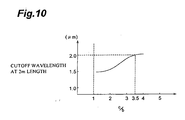
- the embodiment of the dispersion-shifted fiber satisfies the relationship of c/b ⁇ 3.5, its cutoff wavelength can favorably be made shorter, thereby making it easy to secure a wavelength range of signal light which allows single-mode transmission.
- the embodiment of the dispersion-shifted fiber according to the invention has a depressed cladding/segmented-core type refractive index profile.
- the embodiment of the dispersion-shifted fiber according to the invention comprises an inner core having a predetermined refractive index and an outside diameter of 2a; an intermediate core, disposed around the outer periphery of the inner core, having a refractive index lower than that of the inner core and an outside diameter of 2b; an outer core, disposed around the outer periphery of the intermediate core, having a refractive index higher than that of the intermediate core and an outside diameter of 2c; an inner cladding, disposed around the outer periphery of the outer core, having a refractive index lower than that of the outer core; and an outer cladding, disposed around the outer periphery of the inner cladding, having a refractive index higher than that of the inner cladding.
- the embodiment of the dispersion-shifted fiber according to the invention satisfies the following relationships: a/c ⁇ 0.42 b/c ⁇ 0.60 0.5% ⁇ ⁇ n 1 ⁇ 1.1% 0.2% ⁇ ⁇ n 3 - ⁇ n 2 ⁇ 0.7% ⁇ n 4 / ⁇ n 3 ⁇ 0.95 wherein ⁇ n 1 is a relative refractive index difference of said inner core with respect to said inner cladding, ⁇ n 2 is a relative refractive index difference of said intermediate core with respect to said inner cladding, ⁇ n 3 is a relative refractive index difference of said outer core with respect to said inner cladding, and ⁇ n 4 is a relative refractive index difference of said outer cladding with respect to said inner cladding.
- the above-relationships (9) and (10) are conditions to satisfy the effective core cross-section area A eff of 70 ⁇ m 2 .
- the relative refractive index difference ⁇ n 1 of said inner core with respect to said inner cladding is preferably 0.5 % or more in order to satisfy the condition that the dispersion level in terms of absolute value falls within 1.0 to 4.5 ps/nm/km. Further, when the relative index difference ⁇ n 1 is 1.1 % or less, the dispersion slope at wavelength of 1,550 nm falls within a range of 0.09 to 0.13 ps/nm 2 /km.
- the value ( ⁇ n 3 - ⁇ n 2 ) should be 0.2 % or more in order to satisfy the condition that the bending loss when bent at a diameter of 32 mm becomes 0.5 dB/turn or less, and it should be 0.7 % or less in order to make cutoff wavelength at a length of 2 m set 2.2 ⁇ m or less.
- the relationship (13) is a condition to restrain the transmission loss with respect to light in a 1.55- ⁇ m wavelength band so as not to exceed 0.25 dB/km.
- the embodiment of the dispersion-shifted fiber satisfies the following relationship: 1.2 ⁇ d/c ⁇ 3.5 wherein 2d is an outside diameter of the inner cladding.
- the bending loss when bent at a diameter of 32 mm becomes 0.5 dB/km or less when (d/c) is not less than 1.2, and the reducing effect of the cutoff wavelength becomes saturated when (d/c) exceeds 3.5.
- Fig. 2 is a view showing a cross-sectional configuration of a typical embodiment of the dispersion-shifted fiber and its refractive index profile.
- this dispersion-shifted fiber 100 comprises an inner core 110 having a refractive index n 1 as its maximum refractive index and an outside diameter 2a; an outer core 120, disposed around the outer periphery of the inner core 110, having a refractive index n 2 ( ⁇ n 1 ) and an outside diameter 2b; an inner cladding 210, disposed around the outer periphery of the outer core 120, having a refractive index n 3 ( ⁇ n 2 ) and an outside diameter 2c; and an outer cladding 220, disposed around the outer periphery of the inner cladding 210, having a refractive index n 4 (> n 3 ).
- the dispersion-shifted fiber 100 realizes a depressed cladding/dual-shape core type refractive index profile
- This dispersion-shifted fiber satisfies the following relationships: a/b ⁇ 0.15 0.8% ⁇ ⁇ n 1 ⁇ 1.2% 0.12% ⁇ ⁇ n 2 ⁇ 0.30% ⁇ n 3 / ⁇ n 2 ⁇ 0.95 1.2 ⁇ c/b ⁇ 3.5 wherein ⁇ n 1 is a relative refractive index difference of the inner core 110 with respect to the inner cladding 210, ⁇ n 2 is a relative refractive index difference of the outer core 120 with respect to the inner cladding 210, and ⁇ n 3 is a relative refractive index difference of the outer cladding 220 with respect to the inner cladding 210.
- Fig. 3 is a graph showing a relationship between the ratio of outside diameter 2a of the inner core 110 to outside diameter 2b of the outer core 120 and effective core cross-sectional area A eff .
- ⁇ n 1 is 1.0% and ⁇ n 2 is 0.2%
- the outside diameter 2a and the outside diameter 2b of the inner core 110 are changed so as to attain a zero-dispersion wavelength of 1,580 nm.
- a eff becomes 70 ⁇ m 2 or more when (a/b) does not exceed 0.15.
- Fig. 4 is a graph showing a relationship between the relative refractive index difference ⁇ n 1 of the inner core 110 with respect to the inner cladding 210 and absolute value
- the outside diameter 2a of the inner core 110, outside diameter 2b of the outer core 120, relative refractive index difference ⁇ n 1 of the inner core 110 with respect to the inner cladding 210, and relative refractive index difference ⁇ n 2 of the outer core 120 with respect to the inner cladding 210 are changed so as to satisfy that (a/b) is 0.13 and A eff is 80 ⁇ m 2 .
- is equal to or larger than 1.0 ps/nm/km when ⁇ n 1 exceeds 0.8%, and that
- Fig. 5 is a graph showing a relationship between the relative refractive index difference ⁇ n 1 of the inner core 110 with respect to the inner cladding 210 and dispersion slope.
- the outside diameter 2a of the inner core 110, outside diameter 2b of the outer core 120, relative refractive index difference ⁇ n 1 of the inner core 110 with respect to the inner cladding 210, and relative refractive index difference ⁇ n 2 of the outer core 120 with respect to the inner cladding 210 are changed so as to satisfy 0.13 of (a/b), 80 ⁇ m 2 of A eff , 0.1 dB/turn of bending loss when bent at a diameter of 32 mm, and 1,580 nm of zero-dispersion wavelength. It can be seen from Fig. 5 that the dispersion slope becomes 0.13 ps/nm 2 /km or more when ⁇ n 1 is equal to or greater than 1.2%.
- Fig. 6 is a graph showing a relationship between the relative refractive index difference ⁇ n 2 of the outer core 120 with respect to the inner cladding 210 and bending loss generated when bent at a diameter of 32 mm.
- the outside diameter 2a of the inner core 110, outside diameter 2b of the outer core 120, and relative refractive index difference ⁇ n 2 of the outer core 120 with respect to the inner cladding 210 are changed so as to satisfy that relative refractive index difference ⁇ n 1 is 1.0% in the inner core 110 with respect to the inner cladding 210, (a/b) is 0.13, A eff is 80 ⁇ m 2 , and zero-dispersion wavelength is 1,580 nm. It can be seen from Fig.
- the bending loss upon bending at a diameter of 32 mm is 0.5 dB/turn or less when ⁇ n 2 is equal to or greater than 0.12%.
- the bending loss is measured as a fiber to be measured is wound around a mandrel having a diameter of 32 mm by a predetermined number of turns (e.g., 100 turns), and is given by a value obtained when thus measured value is expressed per turn.
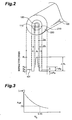
- Fig. 7 is a graph showing a relationship between the relative refractive index difference ⁇ n 2 of the outer core 120 with respect to the inner cladding 210 and cutoff wavelength at a reference length of 2 m.
- the outside diameter 2a of the inner core 110, outside diameter 2b of the outer core 120, relative refractive index difference ⁇ n 2 of the outer core 120 with respect to the inner cladding 210, and relative refractive index difference ⁇ n 3 of the outer cladding 220 with respect to the inner cladding 210 are changed so as to satisfy that ⁇ n 1 is 1.0% in the inner core 110 with respect to the inner cladding 210, (a/b) is 0.13, A eff is 80 ⁇ m 2 , zero-dispersion wavelength is 1,580 nm, and ⁇ n 3 / ⁇ n 2 is 0.8.
- cutoff wavelength ⁇ c of an optical fiber is measured according to a bending process performed at a length of 2 m, which is recommended by CCITT-G.650.
- the dispersion-shifted fiber is assumed to transmit signal light having a wavelength in the band of 1.55 ⁇ m over a long distance of 20 km or more. Consequently, it is necessary for the cutoff wavelength ⁇ c (L 0 ) at a length of 2 m to satisfy the following expression (16): ⁇ c (L) ⁇ 1.5 + 0.732 [ ⁇ m] ⁇ 2.2 ⁇ m
- the cutoff wavelength ⁇ c (L 0 ) is equal to or less than 2.2 ⁇ m at a length of 2 m when ⁇ n 2 ⁇ 0.30%.
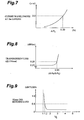
- Fig. 8 is a graph showing a relationship between value ( ⁇ n 3 / ⁇ n 2 ) and transmission loss.
- the relative refractive index difference ⁇ n 3 of the outer cladding 220 with respect to the inner cladding 210 is changed under the following conditions:
- Fig. 9 is a graph showing a relationship between value (c/b) and bending loss at a diameter of 32 mm.
- the outside diameter 2c of the inner cladding 210 is changed.under the following conditions:
- Fig. 10 is a graph showing a relationship between value (c/b) and cutoff wavelength at a length of 2 m.
- the outside diameter 2c of the inner cladding 210 is changed under the following conditions:
- the dispersion-shifted fiber has a depressed cladding/dual-shape core type refractive index profile, it satisfies the following relationships: a/b ⁇ 0.15 0.8% ⁇ ⁇ n 1 ⁇ 1.2% 0.12% ⁇ ⁇ n 2 ⁇ 0.30% ⁇ n 3 / ⁇ n 2 ⁇ 0.95 1.2 ⁇ c/b ⁇ 3.5
- a dispersion level of 1.0 to 4.5 ps/nm/km in terms of absolute value a dispersion slope not greater than 0.13 ps/nm 2 /km in terms of absolute value
- an effective core cross-sectional area A eff of 70 ⁇ m 2 or more a transmission loss not greater than 0.25 dB/km with respect to light in the wavelength band of 1.55 ⁇ m, and a bending loss of 0.5 dB/turn or less when bent at a diameter of 32 mm.
- the dispersion-shifted fiber has a segmented-core type refractive index profile and comprises an inner core having a predetermined refractive index and an outside diameter of 2a; an intermediate core, disposed around the outer periphery of the inner core, having a refractive index lower than that of the inner core and an outside diameter of 2b; an outer core, disposed around the outer periphery of the intermediate core, having a refractive index higher than that of the intermediate core and an outside diameter of 2c; an inner cladding, disposed around the outer periphery of the outer core, having a refractive index lower than that of the outer core and an outside diameter of 2d; and an outer cladding, disposed around the outer periphery of the inner cladding, having a refractive index higher than that of the inner cladding.
- the dispersion-shifted fiber having the above-mentioned various characteristics should satisfy the following relationships: a/c ⁇ 0.42 b/c ⁇ 0.60 0.5% ⁇ ⁇ n 1 ⁇ 1.1% 0.2% ⁇ ⁇ n 3 - ⁇ n 2 ⁇ 0.7% ⁇ n 4 / ⁇ n 3 ⁇ 0.95 1.2 ⁇ d/c ⁇ 3.5
- ⁇ n 1 is a relative refractive index difference of said inner core with respect to said inner cladding
- ⁇ n 2 is a relative refractive index difference of said intermediate core with respect to said inner cladding
- ⁇ n 3 is a relative refractive index difference of said outer core with respect to said inner cladding
- ⁇ n 4 is a relative refractive index difference of said outer cladding with respect to said inner cladding.
- 2d is an outside diameter of the inner cladding.
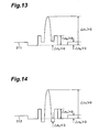
- Fig. 11 is a view showing a cross-sectional configuration of a typical example (dual-shape core type) of a dispersion-shifted fiber according to an example not part of the prevent invention and its refractive index profile. As shown in Fig.
- the dispersion-shifted fiber 200 has a depressed cladding/dual-shape core type refractive index profile 201 and comprises an inner core 111 having an outside diameter of 4.2 ⁇ m; an outer core 121, disposed around the outer periphery of the inner core 111, having an outside diameter 2b of 32 ⁇ m; an inner cladding 211, disposed around the outer periphery of the outer core 121, having an outside diameter 2c of 63 ⁇ m; and an outer cladding 221 disposed around the outer periphery of the inner cladding 211.
- characteristics of this example of the dispersion-shifted fiber measured at the wavelength of 1,500 nm are as follows:
- Fig. 12 is a view showing a cross-sectional configuration of the embodiment of the dispersion-shifted fiber according to the present invention and its refractive index profile.
- the embodiment of the dispersion-shifted fiber 300 has a segmented-core type refractive index profile and comprises an inner core 301 having an outside diameter 2 a of 7.0 ⁇ m; an intermediate core 302, disposed around the outer periphery of the inner core 301, having an outside diameter 2b of 13.4 ⁇ m; an outer core 303, disposed around the outer periphery of the intermediate core 302, having an outside diameter 2c of 19.2 ⁇ m; an inner cladding 304, disposed around the outer periphery of the outer core 303, having an outside diameter 2d of 38.4 ⁇ m; and an outer cladding 305 disposed around the outer periphery of the inner cladding 304.
- the depressed cladding/segmented-core type refractive index profile can be modified in various manners as shown in Figs. 13 and 14.
- Fig. 14 shows a second application of the depressed cladding/segmented-core type refractive index profile at the condition that the refractive index of the intermediate core 302 is lower than that of the inner cladding 304 ( ⁇ n 2 ⁇ 0).
- characteristics of the embodiment of the dispersion-shifted fiber measured at the wavelength of 1,550 nm are as follows:
- the dispersion-shifted fiber in the dispersion-shifted fiber according to the present invention, its zero-dispersion wavelength does not exist at least within the wavelength range of 1.53 to 1.56 ⁇ m, while its effective core cross-sectional area is set to 70 ⁇ m 2 or greater, nonlinear optical effects are effectively restrained from occurring. Accordingly, it is possible to favorably realize a dispersion-shifted fiber, suitable for long-haul light transmission, which can effectively restrain the nonlinear optical effects from occurring.
- the dispersion-shifted fiber according to the present invention has a configuration with a segmented-core type refractive index profile, it can reduce bending loss and favorably realize the aimed dispersion-shifted fiber.
Landscapes
- Chemical & Material Sciences (AREA)
- Physics & Mathematics (AREA)
- Dispersion Chemistry (AREA)
- General Physics & Mathematics (AREA)
- Optics & Photonics (AREA)
- Engineering & Computer Science (AREA)
- Life Sciences & Earth Sciences (AREA)
- General Chemical & Material Sciences (AREA)
- Chemical Kinetics & Catalysis (AREA)
- General Life Sciences & Earth Sciences (AREA)
- Geochemistry & Mineralogy (AREA)
- Manufacturing & Machinery (AREA)
- Materials Engineering (AREA)
- Organic Chemistry (AREA)
- Thermal Sciences (AREA)
- Optical Communication System (AREA)
- Optical Modulation, Optical Deflection, Nonlinear Optics, Optical Demodulation, Optical Logic Elements (AREA)
Claims (5)
- Dispersionsverschobene Faser (100, 200, 300) mit einer dispersionsfreien Wellenlänge außerhalb eines Wellenlängen-Bandes von 1,53 bis 1,56 µm, wobei die Faser einen Kernbereich (110, 120; 111, 121; 301, 302, 303) und einen Mantelbereich (210, 220; 211, 221; 304, 305) aufweist, angeordnet, ein wünschenswertes Brechungsindexprofil vorzusehen;
wobei der Kernbereich umfasst:gekennzeichnet dadurch, dass das Brechungsindexprofil der dispersionsverschobenen Faser eine Kombination der folgenden Charakteristika vorsieht:einen inneren Kern (301) mit einem vorbestimmten Brechungsindex und einem Außendurchmesser von 2a;einen Zwischenkern (302), angeordnet um den äußeren Umfang des inneren Kerns (301), wobei der Zwischenkern (302) einen Brechungsindex, der kleiner als der des inneren Kerns (301) ist, und einen Außendurchmesser von 2b aufweist;einen äußeren Kern (303), angeordnet um den äußeren Umfang des Zwischenkerns (302), wobei der äußere Kern einen Brechungsindex, der größer als der des Zwischenkerns (302) ist, und einen Außendurchmesser von 2c aufweist;und wobei der Mantelbereich umfasst:einen inneren Mantel (304), angeordnet um den äußeren Umfang des äußeren Kerns (303), wobei der innere Mantel (304) einen Brechungsindex, der kleiner als der des äußeren Kerns (303) ist, aufweist; undeinen äußeren Mantel (305), angeordnet um den äußeren Umfang des inneren Mantels (304), wobei der äußere Mantel (305) einen Brechungsindex, der größer als der des inneren Mantels (304) ist, aufweist;wobei Δn1 eine relative Brechungsindex-Differenz des inneren Kerns (301) bezüglich des inneren Mantels (304) ist, Δn2 eine relative Brechungsindex-Differenz des Zwischenkerns (302) bezüglich des inneren Mantels (304) ist, Δn3 eine relative Brechungsindex-Differenz des äußeren Kerns (303) bezüglich des inneren Mantels (304) ist, und Δn4 eine relative Brechungsindex-Differenz des äußeren Mantels (305) bezüglich des inneren Mantels (304) ist.einen Dispersionsgrad von 1,0 bis 4,5 ps/nm/km bezüglich des Absolutwertes bei einer Wellenlänge von 1550 nm;eine Dispersionssteilheit von nicht mehr als 0,13 ps/nm2/km bezüglich des Absolutwertes bei einer Wellenlänge von 1550 nm;eine Wirkfläche mit nicht weniger als 70 µm2 bei der Wellenlänge von 1550 nm;einen Übertragungsverlust von nicht mehr als 0,25 dB/km bezüglich des Lichts in einem 1,55-µm-Wellenlängen-Band; undeine cutoff-Wellenlänge von nicht mehr als 2,2 µm bei einer Länge von 2m;und dadurch, dass die dispersionsverschobene Faser den folgenden Beziehungen genügt: - Dispersionsverschobene Faser nach Anspruch 1, wobei die Werte des Durchmessers und Indices der unterschiedlichen Zonen so gewählt sind, dass die Faser einen Biegungsverlust von nicht größer als 0,5 dB/Windung bezüglich des Lichts im 1,55-µm-Wellenlängen-Band aufweist, wenn sie in einen Durchmesser von 32 mm gebogen wird.
- Dispersionsverschobene Faser nach Anspruch 1, wobei die Werte des Durchmessers und Indices der unterschiedlichen Zonen so gewählt sind, dass die Faser eine Dispersionssteilheit bezüglich des Absolutwertes von nicht weniger als 0,09 ps/nm2/km bei der Wellenlänge von 1550 nm aufweist.
- Dispersionsverschobene Faser nach Anspruch 1, wobei die dispersionsverschobene Faser der folgenden Beziehung genügt:
- Dispersionsverschobene Faser nach Anspruch 1, wobei die Werte des Durchmessers und Indices der unterschiedlichen Zonen so gewählt sind, dass die Faser eine cutoff-Wellenlänge bei einer Länge von 2m von nicht kleiner als 1,59 µm und nicht größer als 2,2 µm darstellt.
Applications Claiming Priority (3)
| Application Number | Priority Date | Filing Date | Title |
|---|---|---|---|
| JP35069196 | 1996-12-27 | ||
| JP35069196 | 1996-12-27 | ||
| EP97122941A EP0851245B1 (de) | 1996-12-27 | 1997-12-29 | Dispersions-verschobene Glasfaser |
Related Parent Applications (2)
| Application Number | Title | Priority Date | Filing Date |
|---|---|---|---|
| EP97122941.4 Division | 1997-12-29 | ||
| EP97122941A Division EP0851245B1 (de) | 1996-12-27 | 1997-12-29 | Dispersions-verschobene Glasfaser |
Publications (3)
| Publication Number | Publication Date |
|---|---|
| EP1233287A2 EP1233287A2 (de) | 2002-08-21 |
| EP1233287A3 EP1233287A3 (de) | 2002-10-09 |
| EP1233287B1 true EP1233287B1 (de) | 2005-09-07 |
Family
ID=18412195
Family Applications (2)
| Application Number | Title | Priority Date | Filing Date |
|---|---|---|---|
| EP02008187A Expired - Lifetime EP1233287B1 (de) | 1996-12-27 | 1997-12-29 | Dispersionsverschobene Faser |
| EP97122941A Expired - Lifetime EP0851245B1 (de) | 1996-12-27 | 1997-12-29 | Dispersions-verschobene Glasfaser |
Family Applications After (1)
| Application Number | Title | Priority Date | Filing Date |
|---|---|---|---|
| EP97122941A Expired - Lifetime EP0851245B1 (de) | 1996-12-27 | 1997-12-29 | Dispersions-verschobene Glasfaser |
Country Status (10)
| Country | Link |
|---|---|
| US (2) | US6072929A (de) |
| EP (2) | EP1233287B1 (de) |
| KR (1) | KR100301882B1 (de) |
| CN (1) | CN1116617C (de) |
| AU (1) | AU733584B2 (de) |
| CA (1) | CA2225889A1 (de) |
| DE (2) | DE69719302T2 (de) |
| HK (1) | HK1009184A1 (de) |
| ID (1) | ID19348A (de) |
| TW (1) | TW359760B (de) |
Families Citing this family (63)
| Publication number | Priority date | Publication date | Assignee | Title |
|---|---|---|---|---|
| US5835655A (en) | 1995-01-26 | 1998-11-10 | Corning Incorporated | Large effective area waveguide fiber |
| CA2225889A1 (en) * | 1996-12-27 | 1998-06-27 | Sumitomo Electric Industries, Ltd. | Dispersion-shifted fiber |
| DE69836402T2 (de) | 1997-09-12 | 2007-09-20 | Corning Inc. | Optischer Wellenleiter mit niedriger Dämpfung |
| WO1999022257A1 (en) | 1997-10-29 | 1999-05-06 | Corning Incorporated | Waveguide profile for large effective area |
| AU740596B2 (en) * | 1997-12-05 | 2001-11-08 | Sumitomo Electric Industries, Ltd. | Dispersion-shifted optical fiber |
| ID22381A (id) * | 1997-12-05 | 1999-10-07 | Sumitomo Electric Industries | Serat optik dengan dispersi yang dipersempit |
| US6421490B1 (en) | 1998-02-23 | 2002-07-16 | Corning Incorporated | Low slope dispersion managed waveguide |
| US6396986B1 (en) * | 1998-04-22 | 2002-05-28 | Corning Incorporated | Method of making optical fibers |
| KR100322131B1 (ko) * | 1999-01-28 | 2002-02-04 | 윤종용 | 오.에이치.차단층을 구비한 광섬유 모재 및 그 제조방법 |
| US6343176B1 (en) | 1998-07-31 | 2002-01-29 | Corning Incorporated | Long haul single mode waveguide |
| DE19839870A1 (de) | 1998-09-02 | 2000-03-09 | Deutsche Telekom Ag | Optische Single-Mode-Lichtleitfaser |
| US6212322B1 (en) | 1998-09-11 | 2001-04-03 | Corning Incorporated | Positive dispersion low dispersion slope fiber |
| FR2783609B1 (fr) | 1998-09-17 | 2002-08-30 | Cit Alcatel | Fibre optique monomode optimisee pour les hauts debits |
| JP4499288B2 (ja) | 1998-09-17 | 2010-07-07 | アルカテル−ルーセント | Wdm光ファイバ伝送システム用の有効面積と分散勾配との最適化された比を有する光ファイバ |
| WO2000017684A1 (fr) * | 1998-09-18 | 2000-03-30 | Sumitomo Electric Industries, Ltd. | Fibre a compensation de dispersion |
| FR2784198B1 (fr) * | 1998-10-05 | 2002-08-30 | Cit Alcatel | Fibre optique utilisable pour systeme de transmissions a multiplexage en longueur d'onde |
| WO2000031573A1 (fr) | 1998-11-26 | 2000-06-02 | Sumitomo Electric Industries, Ltd. | Fibre optique et systeme de transmission optique renfermant celle-ci |
| US6233387B1 (en) * | 1998-11-30 | 2001-05-15 | Corning Incorporated | Broadband pulse-reshaping optical fiber |
| US6337942B1 (en) * | 1998-12-17 | 2002-01-08 | Sumitomo Electric Industries, Ltd. | Optical fiber |
| DE69912990T2 (de) * | 1998-12-17 | 2004-09-02 | Sumitomo Electric Industries, Ltd. | Optische faser |
| US6650842B1 (en) * | 1998-12-18 | 2003-11-18 | Worldcom, Inc. | Optical link with reduced four-wave mixing |
| AU2825800A (en) * | 1999-03-03 | 2000-09-21 | Sumitomo Electric Industries, Ltd. | Optical fiber |
| TW463473B (en) | 1999-03-09 | 2001-11-11 | Sumitomo Electric Industries | Light communication system |
| EP1107027B1 (de) * | 1999-04-13 | 2011-10-12 | Sumitomo Electric Industries, Ltd. | Optischer faser und optischer übertragungssystem mit eine solche optische faser |
| TW451088B (en) | 1999-04-16 | 2001-08-21 | Sumitomo Electric Industries | Optical fiber and optical transmission line including the same |
| US6301422B1 (en) * | 1999-04-28 | 2001-10-09 | Corning Incorporated | Large effective area fiber having a low total dispersion slope |
| JP2000347056A (ja) * | 1999-06-08 | 2000-12-15 | Sumitomo Electric Ind Ltd | 分散補償光ファイバおよび光伝送システム |
| EP1116969A1 (de) * | 1999-06-25 | 2001-07-18 | The Furukawa Electric Co., Ltd. | Dispersionskompensierte glasfaser und optische übertragungsstrecke |
| RU2216756C2 (ru) | 1999-07-12 | 2003-11-20 | Фудзикура Лтд. | Оптическое волокно со смещенной дисперсией |
| MXPA02000925A (es) | 1999-07-27 | 2002-07-30 | Corning Inc | Guia de onda optica que tiene dispersion negativa y gran area efectiva. |
| EP1116972A4 (de) * | 1999-07-27 | 2005-10-19 | Fujikura Ltd | Dispersionsverschobene optische faser |
| EP1124145A1 (de) * | 1999-08-20 | 2001-08-16 | The Furukawa Electric Co., Ltd. | Optische faser und eine diese enthaltende optische übertragungsleitung |
| US6430346B1 (en) | 1999-09-03 | 2002-08-06 | Corning Incorporated | Negative dispersion single mode waveguide fiber |
| CN100343705C (zh) * | 1999-09-09 | 2007-10-17 | 株式会社藤仓 | 色散位移光纤 |
| US6490396B1 (en) | 1999-09-29 | 2002-12-03 | Corning Incorporated | Optical waveguide fiber |
| US6424778B1 (en) | 1999-09-29 | 2002-07-23 | Corning Incorporated | Optical fiber with large effective area and low dispersion slope for submarine applications |
| KR100802251B1 (ko) | 1999-11-22 | 2008-02-11 | 코닝 인코포레이티드 | 유효면적이 큰 분산 시프트 도파관 섬유 |
| US6324327B1 (en) | 1999-11-23 | 2001-11-27 | Corning Incorporated | Low dispersion slope negative dispersion optical fiber |
| US6775451B1 (en) | 1999-12-30 | 2004-08-10 | Corning Incorporated | Secondary coating composition for optical fibers |
| AU3261901A (en) | 1999-12-30 | 2001-07-16 | Corning Incorporated | Coated optical waveguide and method of coating |
| US6453102B1 (en) | 2000-02-07 | 2002-09-17 | Corning Incorporated | Dispersion compensating module and mode converter, coupler and dispersion compensating optical waveguide therein |
| US6584263B2 (en) | 2000-07-26 | 2003-06-24 | Corning Incorporated | Optical fiber coating compositions and coated optical fibers |
| AU2002231425A1 (en) | 2000-08-16 | 2002-02-25 | Corning Incorporated | Optical fiber with large effective area, low dispersion and low dispersion slope |
| US6490398B2 (en) * | 2001-02-21 | 2002-12-03 | Fitel Usa Corp. | Dispersion-compensating fiber having a high figure of merit |
| JP3784656B2 (ja) * | 2001-03-15 | 2006-06-14 | 株式会社フジクラ | 分散補償光ファイバおよびこれを用いた分散補償モジュールと光ファイバ複合伝送路 |
| US6771865B2 (en) * | 2002-03-20 | 2004-08-03 | Corning Incorporated | Low bend loss optical fiber and components made therefrom |
| JP2004037503A (ja) * | 2002-06-28 | 2004-02-05 | Furukawa Electric Co Ltd:The | 光ファイバ |
| US20040022509A1 (en) * | 2002-07-31 | 2004-02-05 | Pushkar Tandon | Non-zero dispersion shifted optical fiber with depressed core having large effective area, low slope and low dispersion |
| US6707976B1 (en) * | 2002-09-04 | 2004-03-16 | Fitel Usa Corporation | Inverse dispersion compensating fiber |
| US6952519B2 (en) * | 2003-05-02 | 2005-10-04 | Corning Incorporated | Large effective area high SBS threshold optical fiber |
| US7085464B2 (en) * | 2004-01-26 | 2006-08-01 | The Furukawa Electric Co., Ltd. | Optical fiber having high nonlinearity |
| JP4219825B2 (ja) * | 2004-01-26 | 2009-02-04 | 古河電気工業株式会社 | 非線形分散シフト光ファイバ |
| US7082243B2 (en) * | 2004-04-05 | 2006-07-25 | Corning Incorporated | Large effective area high SBS threshold optical fiber |
| KR100651506B1 (ko) * | 2004-05-13 | 2006-11-29 | 삼성전자주식회사 | 장거리 광 통신망을 위한 광섬유 |
| KR100735239B1 (ko) * | 2004-05-28 | 2007-07-03 | 삼성전자주식회사 | 메트로 망용 광섬유 |
| CN1847179B (zh) * | 2005-04-13 | 2010-09-08 | 富通集团有限公司 | 一种光纤预制棒生产方法 |
| US8620126B2 (en) * | 2007-03-15 | 2013-12-31 | Nlight Oy | Optical fiber structure and a method of producing thereof |
| WO2008136918A2 (en) * | 2007-05-07 | 2008-11-13 | Corning Incorporated | Large effective area fiber |
| FR2929716B1 (fr) * | 2008-04-04 | 2011-09-16 | Draka Comteq France Sa | Fibre optique a dispersion decalee. |
| JP5823035B2 (ja) * | 2011-07-07 | 2015-11-25 | オーエフエス ファイテル,エルエルシー | 摂動に強い非線形ファイバ |
| JP6255772B2 (ja) * | 2013-07-29 | 2018-01-10 | 住友電気工業株式会社 | 光ファイバおよび光伝送システム |
| WO2020101970A1 (en) * | 2018-11-12 | 2020-05-22 | Panasonic intellectual property Management co., Ltd | Optical fiber structures and methods for beam shaping |
| US11719897B2 (en) * | 2019-03-28 | 2023-08-08 | Panasonic Intellectual Property Management Co., Ltd. | Material processing utilizing high-frequency beam shaping |
Family Cites Families (15)
| Publication number | Priority date | Publication date | Assignee | Title |
|---|---|---|---|---|
| JPS638707A (ja) * | 1986-06-30 | 1988-01-14 | Fujikura Ltd | 分散シフト光フアイバ |
| US4852968A (en) * | 1986-08-08 | 1989-08-01 | American Telephone And Telegraph Company, At&T Bell Laboratories | Optical fiber comprising a refractive index trench |
| JP2831363B2 (ja) * | 1988-11-22 | 1998-12-02 | 株式会社フジクラ | 光ファイバ |
| JP3098828B2 (ja) * | 1991-12-09 | 2000-10-16 | 住友電気工業株式会社 | 分散シフトファイバ及びその製造方法 |
| US5327516A (en) * | 1993-05-28 | 1994-07-05 | At&T Bell Laboratories | Optical fiber for wavelength division multiplexing |
| US5559921A (en) * | 1994-06-24 | 1996-09-24 | Sumitomo Electric Industries, Ltd. | Single mode optical fiber |
| US5483612A (en) * | 1994-10-17 | 1996-01-09 | Corning Incorporated | Increased capacity optical waveguide |
| US5835655A (en) | 1995-01-26 | 1998-11-10 | Corning Incorporated | Large effective area waveguide fiber |
| US5781648A (en) | 1995-04-07 | 1998-07-14 | California Institute Of Technology | Pulse domain neuromorphic integrated circuit for computing motion |
| JPH09211249A (ja) * | 1995-11-28 | 1997-08-15 | Sumitomo Electric Ind Ltd | シングルモード光ファイバ |
| JP3369389B2 (ja) * | 1996-02-08 | 2003-01-20 | 住友電気工業株式会社 | 分散シフト光ファイバ |
| AU715435B2 (en) * | 1996-02-12 | 2000-02-03 | Corning Incorporated | Single mode optical waveguide having large effective area |
| US5684909A (en) * | 1996-02-23 | 1997-11-04 | Corning Inc | Large effective area single mode optical waveguide |
| US5781684A (en) | 1996-12-20 | 1998-07-14 | Corning Incorporated | Single mode optical waveguide having large effective area |
| CA2225889A1 (en) * | 1996-12-27 | 1998-06-27 | Sumitomo Electric Industries, Ltd. | Dispersion-shifted fiber |
-
1997
- 1997-12-23 CA CA002225889A patent/CA2225889A1/en not_active Abandoned
- 1997-12-24 AU AU49252/97A patent/AU733584B2/en not_active Ceased
- 1997-12-24 US US08/998,425 patent/US6072929A/en not_active Expired - Lifetime
- 1997-12-24 KR KR1019970072881A patent/KR100301882B1/ko not_active IP Right Cessation
- 1997-12-26 CN CN97123291A patent/CN1116617C/zh not_active Expired - Lifetime
- 1997-12-26 ID IDP973997A patent/ID19348A/id unknown
- 1997-12-26 TW TW086119789A patent/TW359760B/zh active
- 1997-12-29 EP EP02008187A patent/EP1233287B1/de not_active Expired - Lifetime
- 1997-12-29 EP EP97122941A patent/EP0851245B1/de not_active Expired - Lifetime
- 1997-12-29 DE DE69719302T patent/DE69719302T2/de not_active Expired - Fee Related
- 1997-12-29 DE DE69734167T patent/DE69734167T2/de not_active Expired - Lifetime
-
1998
- 1998-08-24 HK HK98110106A patent/HK1009184A1/xx not_active IP Right Cessation
-
2000
- 2000-01-21 US US09/488,643 patent/US6335995B1/en not_active Expired - Lifetime
Also Published As
| Publication number | Publication date |
|---|---|
| EP0851245A3 (de) | 2000-03-15 |
| EP1233287A3 (de) | 2002-10-09 |
| CN1186250A (zh) | 1998-07-01 |
| ID19348A (id) | 1998-07-02 |
| EP0851245A2 (de) | 1998-07-01 |
| CN1116617C (zh) | 2003-07-30 |
| HK1009184A1 (en) | 1999-05-28 |
| DE69719302D1 (de) | 2003-04-03 |
| AU733584B2 (en) | 2001-05-17 |
| DE69734167D1 (de) | 2005-10-13 |
| DE69734167T2 (de) | 2006-06-14 |
| EP0851245B1 (de) | 2003-02-26 |
| DE69719302T2 (de) | 2003-10-16 |
| AU4925297A (en) | 1998-07-02 |
| EP1233287A2 (de) | 2002-08-21 |
| CA2225889A1 (en) | 1998-06-27 |
| US6335995B1 (en) | 2002-01-01 |
| KR100301882B1 (ko) | 2001-10-27 |
| US6072929A (en) | 2000-06-06 |
| KR19980064539A (ko) | 1998-10-07 |
| TW359760B (en) | 1999-06-01 |
Similar Documents
| Publication | Publication Date | Title |
|---|---|---|
| EP1233287B1 (de) | Dispersionsverschobene Faser | |
| US6169837B1 (en) | Dispersion-flattened optical fiber | |
| US6859595B2 (en) | Optical fiber and optical transmission system including the same | |
| AU745736B2 (en) | Dispersion equalization optical fiber and optical transmission line including the same | |
| US6477306B2 (en) | Dispersion-compensating optical fiber, and, optical transmission line and dispersion-compensating module respectively including the same | |
| EP1145057B1 (de) | Optische faser | |
| EP1043609A1 (de) | Dispersionskompensierende optische faser und wellenlängen multiplextransmissionsstrecke mit dispersionskompensierender optischer faser | |
| US6603913B1 (en) | Single-mode optical fiber having multiple cladding regions for dispersion compensation | |
| EP1149479B1 (de) | Optisches system und verfahren mit geringen verlusten und nichtlinearen effekten | |
| US6256440B1 (en) | Dispersion-shifted optical fiber | |
| US6496631B2 (en) | Optical transmission line and optical transmission system including the same | |
| EP0949517A1 (de) | Dispersionsverschiebende faser | |
| US6459839B1 (en) | Phase-shifted monomode optical fibre with large effective area | |
| US6337942B1 (en) | Optical fiber | |
| WO2000051269A9 (en) | High order spatial mode optical fiber | |
| CA2405146A1 (en) | Dispersion-compensating optical fiber with w-shaped index profile | |
| US6229946B1 (en) | Dispersion-shifted optical fiber | |
| JP2000162461A (ja) | 低非線形係数を有するwdm伝送用光ファイバ | |
| AU2004235591A1 (en) | Optical system and method having low loss and non-linear effects |
Legal Events
| Date | Code | Title | Description |
|---|---|---|---|
| PUAI | Public reference made under article 153(3) epc to a published international application that has entered the european phase |
Free format text: ORIGINAL CODE: 0009012 |
|
| 17P | Request for examination filed |
Effective date: 20020514 |
|
| AC | Divisional application: reference to earlier application |
Ref document number: 851245 Country of ref document: EP |
|
| AK | Designated contracting states |
Kind code of ref document: A2 Designated state(s): DE FR GB IT SE |
|
| PUAL | Search report despatched |
Free format text: ORIGINAL CODE: 0009013 |
|
| AK | Designated contracting states |
Kind code of ref document: A3 Designated state(s): DE FR GB IT SE |
|
| AKX | Designation fees paid |
Designated state(s): DE FR GB IT SE |
|
| 17Q | First examination report despatched |
Effective date: 20040506 |
|
| GRAP | Despatch of communication of intention to grant a patent |
Free format text: ORIGINAL CODE: EPIDOSNIGR1 |
|
| GRAS | Grant fee paid |
Free format text: ORIGINAL CODE: EPIDOSNIGR3 |
|
| GRAA | (expected) grant |
Free format text: ORIGINAL CODE: 0009210 |
|
| AC | Divisional application: reference to earlier application |
Ref document number: 0851245 Country of ref document: EP Kind code of ref document: P |
|
| AK | Designated contracting states |
Kind code of ref document: B1 Designated state(s): DE FR GB IT SE |
|
| REG | Reference to a national code |
Ref country code: GB Ref legal event code: FG4D |
|
| REF | Corresponds to: |
Ref document number: 69734167 Country of ref document: DE Date of ref document: 20051013 Kind code of ref document: P |
|
| REG | Reference to a national code |
Ref country code: SE Ref legal event code: TRGR |
|
| ET | Fr: translation filed | ||
| PLBE | No opposition filed within time limit |
Free format text: ORIGINAL CODE: 0009261 |
|
| STAA | Information on the status of an ep patent application or granted ep patent |
Free format text: STATUS: NO OPPOSITION FILED WITHIN TIME LIMIT |
|
| 26N | No opposition filed |
Effective date: 20060608 |
|
| PGFP | Annual fee paid to national office [announced via postgrant information from national office to epo] |
Ref country code: SE Payment date: 20081205 Year of fee payment: 12 |
|
| EUG | Se: european patent has lapsed | ||
| PG25 | Lapsed in a contracting state [announced via postgrant information from national office to epo] |
Ref country code: SE Free format text: LAPSE BECAUSE OF NON-PAYMENT OF DUE FEES Effective date: 20091230 |
|
| REG | Reference to a national code |
Ref country code: FR Ref legal event code: PLFP Year of fee payment: 19 |
|
| REG | Reference to a national code |
Ref country code: FR Ref legal event code: PLFP Year of fee payment: 20 |
|
| PGFP | Annual fee paid to national office [announced via postgrant information from national office to epo] |
Ref country code: DE Payment date: 20161220 Year of fee payment: 20 Ref country code: GB Payment date: 20161228 Year of fee payment: 20 Ref country code: FR Payment date: 20161111 Year of fee payment: 20 |
|
| PGFP | Annual fee paid to national office [announced via postgrant information from national office to epo] |
Ref country code: IT Payment date: 20161221 Year of fee payment: 20 |
|
| REG | Reference to a national code |
Ref country code: DE Ref legal event code: R071 Ref document number: 69734167 Country of ref document: DE |
|
| REG | Reference to a national code |
Ref country code: GB Ref legal event code: PE20 Expiry date: 20171228 |
|
| PG25 | Lapsed in a contracting state [announced via postgrant information from national office to epo] |
Ref country code: GB Free format text: LAPSE BECAUSE OF EXPIRATION OF PROTECTION Effective date: 20171228 |