EP1233216B1 - Robinet à papillon - Google Patents
Robinet à papillon Download PDFInfo
- Publication number
- EP1233216B1 EP1233216B1 EP01130786A EP01130786A EP1233216B1 EP 1233216 B1 EP1233216 B1 EP 1233216B1 EP 01130786 A EP01130786 A EP 01130786A EP 01130786 A EP01130786 A EP 01130786A EP 1233216 B1 EP1233216 B1 EP 1233216B1
- Authority
- EP
- European Patent Office
- Prior art keywords
- butterfly valve
- valve according
- bearing
- shaft
- bush
- Prior art date
- Legal status (The legal status is an assumption and is not a legal conclusion. Google has not performed a legal analysis and makes no representation as to the accuracy of the status listed.)
- Expired - Lifetime
Links
Images


Classifications
-
- F—MECHANICAL ENGINEERING; LIGHTING; HEATING; WEAPONS; BLASTING
- F16—ENGINEERING ELEMENTS AND UNITS; GENERAL MEASURES FOR PRODUCING AND MAINTAINING EFFECTIVE FUNCTIONING OF MACHINES OR INSTALLATIONS; THERMAL INSULATION IN GENERAL
- F16K—VALVES; TAPS; COCKS; ACTUATING-FLOATS; DEVICES FOR VENTING OR AERATING
- F16K1/00—Lift valves or globe valves, i.e. cut-off apparatus with closure members having at least a component of their opening and closing motion perpendicular to the closing faces
- F16K1/16—Lift valves or globe valves, i.e. cut-off apparatus with closure members having at least a component of their opening and closing motion perpendicular to the closing faces with pivoted closure-members
- F16K1/18—Lift valves or globe valves, i.e. cut-off apparatus with closure members having at least a component of their opening and closing motion perpendicular to the closing faces with pivoted closure-members with pivoted discs or flaps
- F16K1/22—Lift valves or globe valves, i.e. cut-off apparatus with closure members having at least a component of their opening and closing motion perpendicular to the closing faces with pivoted closure-members with pivoted discs or flaps with axis of rotation crossing the valve member, e.g. butterfly valves
- F16K1/224—Details of bearings for the axis of rotation
-
- F—MECHANICAL ENGINEERING; LIGHTING; HEATING; WEAPONS; BLASTING
- F16—ENGINEERING ELEMENTS AND UNITS; GENERAL MEASURES FOR PRODUCING AND MAINTAINING EFFECTIVE FUNCTIONING OF MACHINES OR INSTALLATIONS; THERMAL INSULATION IN GENERAL
- F16K—VALVES; TAPS; COCKS; ACTUATING-FLOATS; DEVICES FOR VENTING OR AERATING
- F16K1/00—Lift valves or globe valves, i.e. cut-off apparatus with closure members having at least a component of their opening and closing motion perpendicular to the closing faces
- F16K1/16—Lift valves or globe valves, i.e. cut-off apparatus with closure members having at least a component of their opening and closing motion perpendicular to the closing faces with pivoted closure-members
- F16K1/18—Lift valves or globe valves, i.e. cut-off apparatus with closure members having at least a component of their opening and closing motion perpendicular to the closing faces with pivoted closure-members with pivoted discs or flaps
- F16K1/22—Lift valves or globe valves, i.e. cut-off apparatus with closure members having at least a component of their opening and closing motion perpendicular to the closing faces with pivoted closure-members with pivoted discs or flaps with axis of rotation crossing the valve member, e.g. butterfly valves
- F16K1/226—Shaping or arrangements of the sealing
- F16K1/2261—Shaping or arrangements of the sealing the sealing being arranged on the valve member
Definitions
- the present invention relates to a disc valve for media under High pressure and / or high temperature, according to the preamble of claim 1.
- valves are used as shut-off valves in high-pressure systems, for example between pipelines, pressure vessels, boilers, turbines and / or the like, used.
- a circumferential sealing zone of the valve disc and the circumferential housing-side sealing seat in adaptation to the closing or Opening movement of the valve disc so "conical" formed that in the shut-off position in the case of pressurization from the side on which the shaft runs, the disc is pressed firmly into the sealing seat.
- This will also ensures effective sealing at a very high pressure, and at the same time the disc is also mechanically supported against the pressure.
- such valves are usually designed for both flow directions, so often also the reverse load case occurs, the disc on her the Wave remote side is acted upon by a back pressure.
- a butterfly valve of the generic, the preamble of Claim 1 of this kind is disclosed in document US-A-2 835 268 described.
- a compressible sealing ring sits axially between two annular or female elements and radially directly between the shaft and a bearing opening of the housing. This can result in mounting problems.
- the present invention has for its object, a butterfly valve of the generic type to continue to improve so that on the one hand also after longer service life as well as when used for any media always one trouble-free function to open and close the passage ensures and On the other hand, the valve with a structurally simple design easy and can be mounted quickly.
- At least the remote from the operating end of the shaft Lagerervorabdichtung is about clamping means so axially with a Nachspannkraft acted upon that an adjusting radial compressibility is achieved.
- the other, the operating end of the shaft closest Bearing pre-seal can be acted upon by clamping means for retightening.
- clamping means by spring means such that the or each Lagerervorabdichtung in the axial direction permanently with spring force is applied, so that a permanent self-adjusting radial compression is reached.
- both are preferred Bearing pre-seals at least re-tensioned by maintenance.
- spring means is advantageously an automatic self-adjustment of the seal compression achieved by the spring means the Lagerervorabdichtonne always with almost constant Apply spring force and thus permanently clamp.
- This will be a practical Maintenance-free flap valve created with long service life.
- the further advantage arises that is maintained by the over long time Lagerervorabdichtung also a pressure-induced axial application of force to the shaft is avoided because the pressure medium is kept away from a room in which the end of the shaft opposite an operating end is practically encapsulated is arranged; this space remains through the effective, self-adjusting Bearing pre-seal advantageously pressure-free.
- each Bearing pre-seal a two-piece bearing bush with a shaft directly receiving inner bush and one receiving the inner bush and in one Bearing bore of the housing sitting outer sleeve.
- the passage facing the end portion of the respective rotary bearing axially between the inner bush and a projecting, annular web-shaped end portion of the External bushing a verpreßbares sealing element arranged such that by the axial Pressing the bushing - or the inner sleeve and the outer sleeve relative to each other - by the spring force of the invention, the sealing element also radially permanently pressed inwards against the shaft.
- This preferred embodiment represents a particular advantage with regard to the assembly of the valve disc valve
- the wave can initially easily in the - preferably of each Two-piece bushings formed - Drehlagem by simply pushing to be assembled. Only after this composition then the Lagerervorabdichtungen by axial compression of the bushings by the Spring means braced.
- An inventive butterfly valve 1 consists of a housing 2 with a passage 4 (see Fig. 2 and 4) for a medium and from a shut-off device disposed within the passage 4, substantially circular Valve disc 6.
- This disc 6 is on one side of a disc arranged, guided at both ends in the housing side Drehlagem 8 and across the passage 4 extending shaft 10 to one with respect to their circular shape in essential diametrically extending axis of rotation X-X such rotatable or - more accurate said - pivoted that they in an open position (not in the drawing shown) with its disc plane approximately corresponding to the forward direction or approximately parallel thereto and in the in Figs. 1 and 2 shown, across the Forward passage blocking position the passage 4 occlusive with a outer circumferential sealing zone 12 sealing with a housing side cooperates circumferentially sealing seat 14. This is best in Fig. 2 too detect.
- each of the two Pivot 8 on its the passage 4 facing, inner side 20 a compressible bearing pre-seal 22 between the shaft 10 and the housing second having.
- this has each Lagerervorabdichtung 22 a two-piece bearing bushing 24 with a shaft 10 receiving directly superimposed Inner bush 26 and one receiving the inner bush 26 and in the respective Bearing bore 16 of the housing 2 seated external socket 28.
- These two sockets 26, 28 are seated in each other so that they are axially against each other.
- each inner side 20 of the pivot bearing 8 is axially between the inner sleeve 26 and a projecting, radially inwardly beyond the front end of the inner sleeve 26th projecting, annular web-shaped end portion 30 of the outer sleeve 28 (see Fig. 5) a verpreßbares sealing element 32 arranged such that by an axial compression or bracing the bearing bush 24 - increment. the inner and outer bushings 26, 28th relative to each other - the sealing element 32 also radially between the outer sleeve 28th and the shaft 10 is pressed.
- the annular gap between the shaft 10th and the bearing bush 24 sealed to the side of the passage 4, so that an intrusion prevents the respective medium in the annular gap surrounding the shaft 10 becomes.
- each pivot bearing 8 is also removed on its from the passage 4 lying side 34, a second, outer sealing element 36 such that this second Sealing element 36 by the above-described axial compression of the Bearing 24 also radially outward against the bearing bore 16 of the housing. 2 is pressed.
- the sealing element 36 is seated axially between the outer sleeve 28 and a radially outwardly beyond the front end of the outer sleeve 28 projecting portion 37 of the inner sleeve 26 or a separate pressure bush 26a.
- At least the first, inner sealing element 32 is each Lagerervorabdichtung 22 by a sealing ring package with at least two formed compressible sealing rings 38.
- the two inner sealing elements 32 are preferably made of a three-piece sealing ring package of three compressible sealing rings 38, which are preferably pre-pressed Pure graphite rings acts.
- Each outer sealing element 36 is preferably made a similar sealing ring package of three sealing rings 38th
- the housing-side sealing seat 14 and the sealing zone 12 of the valve disc 6 are tapered "conically” in at least a portion of their circumference in adaptation to the closing pivoting movement of the valve disc 6 formed so that the free flow cross-section in the region of the sealing seat 14, in particular in the direction of the shaft side of the valve disc 6 slightly opposite direction.
- the shaft side of the flap disk 6 is the "pressure side”, which can be acted upon by a pressure p 1 .
- the opposite, facing away from the shaft 10 side of the valve disc 6 is the so-called “back pressure side”, which is acted upon by a pressure p 2 .
- the sealing zone 12 of the valve disc 6 is formed by a separate sealing ring 42, which is shown separately in Fig. 7.
- This sealing ring 42 is held clamped between a base plate 44 of the valve disc 6 and a particular disk-shaped, but possibly also annular disc-shaped clamping element 46 (see Fig. 3 and 6).
- the sealing ring 42 as a lamellar seal consists of several packet-like superimposed individual disks 42a, 42b made of steel (stainless steel).
- the first individual disk 42b of the disk seal 42 arranged on one side, in particular the pressure side p 1 has a thickness D 1 which is greater than the thickness D 2 of the remaining individual disks 42a - see
- the thickness D 1 of the first disc 42b is about 1 mm
- the thickness D 2 of all the remaining discs 42a is about 0.5 mm, for example.
- the individual disks 42a, b are internal Peripheral region of the sealing ring 42 at preferably at least three of the Ring circumference evenly distributed joints 50 cohesively with each other connected, in particular welded.
- this is in each case formed by two-sided incisions 52 approximately radially arranged tongues 54, wherein the welding takes place only in the region of the tongues 54 to thermally induced Avoid deformations of the discs.
- the individual disks 42a, b be pinned or riveted together in their annular area.
- the housing 2 is substantially hollow cylindrical or due to a relatively short flow length is formed approximately annular disc-shaped.
- the housing 2 has two frontal, opposite sealing surfaces 56, the with corresponding mating surfaces of certain, not shown Pressure system components, such as pipelines, pressure vessels, boilers, turbines and like, are flangeable.
- each is Lagervorabdichtung 22 by spring means 60 so permanently in the axial direction
- Spring force F urges that a permanent, self-adjusting radial Compression is achieved.
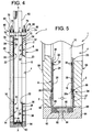
- the shaft 10 is one-sided with a Operating end 62 out of the housing 2 to the outside. On the other side ends the Shaft 10 in a sealed over a cover member 64 housing space.
- the cover member 64 is screwed flush against a housing surface 66, namely about, for example, four in Fig. 4 and 5 unrecognizable screw.
- the Sealing takes place via a sealing ring 68, preferably as so-called Spiral lid gasket made of graphite and in an annular recess in particular of the cover element 64 is arranged.
- the actuation end 62 of the shaft 10 closest (upper) bearing pre-seal 22 is a sleeve-shaped, the shaft 10 enclosing and partially in the housing 2 engaging stuffing box element 70 with the spring force F applied.
- the gland member 70 acts against the Inner bush 26 of the two-part bushing 24, in particular via a additional seal pack 72, which in the annular gap directly between the shaft 10th and the bearing bore 16 is seated, and preferably via a separate pressure bush 26 a.
- the stuffing box element 70 is acted upon by a pressure body 74, the outside of the housing 2 connected to the housing 2 to the shaft 10th parallel stud 76 is seated.
- the pressure body 74 has a central opening for the Wave 10 on.
- each stud 76 between the Pressure element 74 and a housing 2 opposite abutment element 78 at least one compression spring element 80, which for generating the for Preloading required, relatively high spring force F in particular as an off a plurality of disc springs existing spring package is formed.
- the Stud 76 as a screw threaded bolt and the abutment elements 78 as to suitable ringmuttem be formed.
- the spring preload F be preset.
- four studs 76 with corresponding compression spring elements 80 and abutment elements 78 in one force-symmetrical distribution around the shaft 10 around.
- Fig. 5 is the other, arranged on the closed side of the housing 2
- Bearing pre-seal 22 of at least one as a spring means 60 between the Cover member 64 and the inner sleeve 26 of the two-part bearing bushing 24 act Compressed spring 82 acted upon.
- this compression spring 82 is preferred around a spring plate consisting of several disc springs to the required, right high bias spring force F can apply.
- the compression spring 82 is seated in an inner receiving recess 84 of the cover member 64 and acts in particular via a disc-shaped pressure element 86 on the bearing bush 24 or over the preferably existing pressure bushing 26a on the inner sleeve 26.
- the pressure element 86 can sit with advantage without play in a recess of the cover member 64 and while a substantially play in the bearing bush engaging centering approach 88 have. As a result, an automatic centering of the Cover element 64 is achieved relative to the housing 2.
- the invention is not limited to the illustrated and described embodiments limited, but also includes all the same in the context of the invention Versions. Furthermore, the invention has hitherto also not yet been claimed in claim 1 defined feature combination limited, but can also by any arbitrary other combination of certain features of all individual features disclosed be defined. This means that basically every single feature of claim 1 omitted or by at least one to another Site of the application disclosed individual feature can be replaced. Insofar is the Claim 1 merely as a first formulation attempt for an invention understand.
Claims (17)
- Robinet à papillon (1) pour des agents sous haute pression et/ou sous haute température, constituée d'un boítier (2) avec un passage (4) pour l'agent et d'un papillon (6) disposé en tant qu'organe de fermeture à l'intérieur du passage (4), qui par l'intermédiaire d'un arbre (10) guidé des deux côtés dans des coussinets de pivotement (8) et s'étendant à la transversale du passage (4), guidé sur un côté, vers l'extérieur hors du boítier (2) par une extrémité de manoeuvre (62), est pivotant autour d'un axe rotatif (X - X), de façon à ce que dans une position d'ouverture, le plan de son disque s'étende de façon correspondant environ à la direction de passage et dans une position de fermeture située à la transversale de la direction de passage, il soit en interaction d'étanchéité périphérique avec un logement d'étanchéité (14) situé côté boítier, une étanchéité préliminaire de palier (22) étant située en amont de chacun des deux coussinets de pivotement, sur leur face interne (20) dirigée vers le passage (4), de façon à ce qu'une fente annulaire entourant l'arbre (10) dans la zone du coussinet de pivotement respectif (8) soit étanchéifiée par l'intermédiaire d'un élément d'étanchéité compressible (32) contre une pénétration de l'agent à partir du passage (4),
et l'étanchéité préliminaire de palier (22) située à distance de l'extrémité de manoeuvre (62) de l'arbre (10) pouvant être soumise de façon axiale à un rattrapage par l'intermédiaire de moyens de tension, de façon à obtenir une compressibilité radiale de rattrapage,
caractérisée en ce que l'étanchéité préliminaire de palier (22) est munie d'un douille de palier en deux parties (24), avec une douille interne (26) réceptionnant l'arbre (10) et une douille externe (28) logée dans un alésage du roulement (16) du boítier (2), l'élément compressible (32) étant disposé sur le côté interne (20) du coussinet de pivotement (8) de façon axiale entre la douille interne (26) et une section d'extrémité (30) de la douille externe (28), de façon à ce que par une compression axiale de la douille de palier (24), l'élément d'étanchéité (32) soit également comprimé de façon radiale entre la douille externe (28) et vers l'intérieur contre l'arbre (10). - Robinet à papillon selon la revendication 1,
caractérisée en ce que l'autre étanchéité préliminaire de palier (22) qui est la plus proche de l'extrémité de manoeuvre de l'arbre (62) peut aussi être soumise à des moyens de tension pour le rattrapage. - Robinet à papillon selon la revendication 1 ou 2,
caractérisée en ce que les moyens de tension sont formés par des moyens à ressort (60) de façon telle, que l'étanchéité préliminaire de palier (22) est soumise de façon permanente à une force élastique (F) en direction axiale et qu'une compression radiale de rattrapage durable est obtenue. - Robinet à papillon selon l'une quelconque des revendications 1 à 3,
caractérisée en ce que, sur sa face éloignée (34) du passage (4), le/chaque coussinet de pivotement (8) est muni d'un second élément d'étanchéité qui est externe (36), de façon à ce que ce second élément d'étanchéité (36) soit également comprimé contre l'ouverture de roulement (16) du boítier (2), par compression axiale de la douille de palier (24). - Robinet à papillon selon l'une quelconque des revendications 1 à 4,
caractérisée en ce qu'au moins le premier élément d'étanchéité interne (32) de la / de chaque étanchéité préliminaire de palier (22) est formé d'un paquet de bagues d'étanchéité avec au moins deux bagues d'étanchéité (38) compressibles, constituées notamment de graphite pur précomprimé. - Robinet à papillon selon l'une quelconque des revendications 1 à 5,
caractérisée en ce que sur son côté opposé à l'extrémité de manoeuvre (62), l'arbre (10) se termine dans un compartiment du boítier fermé de façon étanche par un élément de recouvrement (64). - Robinet à papillon selon l'une quelconque des revendications 1 à 6,
caractérisée en ce que l'étanchéité préliminaire de palier (22) la plus proche de l'extrémité de manoeuvre (62) de l'arbre (10) est soumise aux moyens de tension par l'intermédiaire d'un élément de presse-étoupe (70) en forme de douille, entourant l'arbre (10) et notamment par l'intermédiaire d'un paquet d'étanchéités supplémentaire (72), ainsi que par l'intermédiaire de la douille interne (26) de la douille de palier (24). - Robinet à papillon selon la revendication 7,
caractérisée en ce que l'élément de presse-étoupe (70) est soumis à un corps de pression (74), qui est muni d'un orifice traversé par l'arbre (10) et qui est logé sur le boítier (2) avec des boulons d'entretoisement (76), au moins un élément à ressort de pression (80), notamment un paquet de ressort constitué de plusieurs ressorts à disque étant logé en tant que moyen de serrage ou en tant que moyen à ressort (60) sur les boulons d'entretoisement (76), respectivement entre le corps de pression (74) et un élément de butée (78). - Robinet à papillon selon la revendication 8,
caractérisée en ce que les boulons d'entretoisement (76) sont conçus en tant que boulons filetés et en ce que les éléments de butée (78) sont conçus en tant qu'écrous. - Robinet à papillon selon la revendication 8 ou 9,
caractérisée en ce que quatre boulons d'entretoisement (76) avec les éléments de ressort de pression (80) et les éléments de butée (78) correspondants sont prévus selon un dispositif à forces symétriques. - Robinet à papillon selon l'une quelconque des revendications 6 à 10,
caractérisée en ce que les étanchéités préliminaires de palier (22) disposées sur le côté fermé du boítier (2) sont soumis à au moins un ressort de pression (82) agissant en tant que moyen de serrage ou en tant que moyen à ressort (60) entre l'élément de recouvrement (64) et la douille interne (26) de la douille de palier (24), notamment à un paquet de ressorts constitué d'un ou de plusieurs ressorts à disque. - Robinet à papillon selon la revendication 11,
caractérisée en ce que le ressort de pression (82) est logé dans un creux de réception interne (84) de l'élément de recouvrement (64) et agit notamment sur la douille de palier (24) par l'intermédiaire d'un élément de pression (86) notamment en forme de disque. - Robinet à papillon selon l'une quelconque des revendications 1 à 12,
caractérisée en ce que la zone d'étanchéité (12) du papillon (6) est formée par une bague d'étanchéité (42) qui est maintenue serrée entre un disque de base (44) du papillon (6) et un élément de serrage (46) en forme de disque ou en forme de disque annulaire. - Robinet à papillon selon la revendication 13,
caractérisée en ce qu'en tant qu'étanchéité à lamelles, la bague d'étanchéité (42) est constituée de disques individuels (42a, b) en acier, superposés en paquet. - Robinet à papillon selon la revendication 14,
caractérisée en ce que dans la zone périphérique interne de la bague d'étanchéité (42), les disques individuels (42a, b) sont reliés entre eux par complémentarité de matière, notamment soudés de préférence en aux moins trois points de liaison (50). - Robinet à papillon selon la revendication 14,
caractérisée en ce que dans leur zone de surface annulaire, les disques individuels (42a, b) sont goupillés ou rivés entre eux. - Robinet à papillon selon l'une quelconque des revendications 14 à 16,
caractérisée en ce que le premier disque individuel (42b) de l'étanchéité à lamelles, qui est disposé sur un côté, notamment un côté pression présente une épaisseur (D1) qui est supérieure à l'épaisseur (D2) des autres disques individuels (42a)
Applications Claiming Priority (2)
| Application Number | Priority Date | Filing Date | Title |
|---|---|---|---|
| US766508 | 2001-01-19 | ||
| US09/766,508 US6595488B2 (en) | 2001-01-19 | 2001-01-19 | Butterfly valve |
Publications (3)
| Publication Number | Publication Date |
|---|---|
| EP1233216A2 EP1233216A2 (fr) | 2002-08-21 |
| EP1233216A3 EP1233216A3 (fr) | 2003-05-21 |
| EP1233216B1 true EP1233216B1 (fr) | 2005-03-02 |
Family
ID=25076644
Family Applications (1)
| Application Number | Title | Priority Date | Filing Date |
|---|---|---|---|
| EP01130786A Expired - Lifetime EP1233216B1 (fr) | 2001-01-19 | 2001-12-22 | Robinet à papillon |
Country Status (3)
| Country | Link |
|---|---|
| US (1) | US6595488B2 (fr) |
| EP (1) | EP1233216B1 (fr) |
| DE (1) | DE50105468D1 (fr) |
Cited By (1)
| Publication number | Priority date | Publication date | Assignee | Title |
|---|---|---|---|---|
| DE102009017510A1 (de) | 2009-04-15 | 2010-10-28 | müller co-ax ag | Lagerabdichtung für Klappen |
Families Citing this family (16)
| Publication number | Priority date | Publication date | Assignee | Title |
|---|---|---|---|---|
| DE10251179A1 (de) * | 2002-10-31 | 2004-05-13 | Siemens Ag | Gehäuseflanscheinheit |
| DE10251385A1 (de) * | 2002-11-01 | 2004-05-13 | Siemens Ag | Ventil |
| US7032883B2 (en) * | 2004-04-07 | 2006-04-25 | Hr Textron, Inc. | Hybrid butterfly fluid control valve |
| DE102004046077A1 (de) * | 2004-09-23 | 2006-04-06 | Pierburg Gmbh | Abgasklappeneinrichtung |
| US20070080314A1 (en) * | 2005-10-06 | 2007-04-12 | Arvin Technologies, Inc. | Exhaust valve bushing |
| DE102007050899A1 (de) * | 2007-10-24 | 2009-04-30 | Continental Automotive Gmbh | Ventil |
| EP2249067A1 (fr) * | 2009-05-04 | 2010-11-10 | Johann Zwick | Soupape de disque à clapets |
| DE102010006023B4 (de) * | 2010-01-27 | 2012-04-26 | Pierburg Gmbh | Dichtungsanordnung für eine Regelvorrichtung einer Verbrennungskraftmaschine |
| WO2015031220A1 (fr) * | 2013-08-28 | 2015-03-05 | Borgwarner Inc. | Joint d'étanchéité d'arbre de vanne à haute température |
| WO2016147072A1 (fr) * | 2015-03-13 | 2016-09-22 | Sol Alva Mecânica De Precisão S.A. | SOUPAPE DE RECIRCULATION DE GAZ DE - 40 ºC À 700 ºC |
| US10844962B2 (en) * | 2015-10-07 | 2020-11-24 | Fisher Controls International Llc | Valve body insert apparatus and related methods |
| CN105202204A (zh) * | 2015-10-12 | 2015-12-30 | 罗普阀业(宜兴)有限公司 | 船用柴油机高温蝶阀 |
| SG11201803270WA (en) * | 2015-11-23 | 2018-05-30 | Victaulic Co Of America | Valve and valve coupling with reverse tapered shafts |
| US9915352B2 (en) | 2016-08-03 | 2018-03-13 | Scc, Inc. | Butterfly valve utilizing spring for consistent disk placement |
| US11391379B2 (en) | 2019-03-29 | 2022-07-19 | Velan Inc. | Butterfly valve and butterfly disc |
| CN113932019A (zh) * | 2021-10-16 | 2022-01-14 | 东宝阀门有限公司 | 一种高压自密封蝶阀 |
Family Cites Families (10)
| Publication number | Priority date | Publication date | Assignee | Title |
|---|---|---|---|---|
| US2835268A (en) * | 1955-08-22 | 1958-05-20 | Clary Corp | Butterfly valve construction |
| DE1179049B (de) * | 1959-07-16 | 1964-10-01 | Zahnradfabrik Friedrichshafen | Auspuffmotorbremse, bestehend aus einer Bremsklappe, die eine durchgehende Bohrung zur Aufnahme einer Klappenwelle aufweist, und aus einem ungeteilten Gehaeuse |
| US3778028A (en) * | 1972-08-02 | 1973-12-11 | Dore Co John L | Lined butterfly valve |
| US3905577A (en) * | 1973-03-08 | 1975-09-16 | Anchor Darling Valve Co | Valve |
| FR2255522B1 (fr) * | 1973-12-19 | 1982-11-12 | Amri | |
| US4217923A (en) * | 1978-03-17 | 1980-08-19 | Kamyr Valves, Inc. | Ball valve with readily removable ball and seats for high temperature environment |
| FR2439348A1 (fr) * | 1978-10-17 | 1980-05-16 | Gachot Jean | Dispositif anti-friction pour arbre de commande de vanne |
| US4759530A (en) * | 1984-11-14 | 1988-07-26 | Neotecha Ag | Stem and disc seal construction for butterfly valves |
| JP3332861B2 (ja) * | 1998-07-24 | 2002-10-07 | 株式会社巴技術研究所 | バタフライ弁 |
| DE29822791U1 (de) | 1998-12-22 | 1999-04-08 | Zwick Armaturen Gmbh | Klappenscheibenventil |
-
2001
- 2001-01-19 US US09/766,508 patent/US6595488B2/en not_active Expired - Lifetime
- 2001-12-22 EP EP01130786A patent/EP1233216B1/fr not_active Expired - Lifetime
- 2001-12-22 DE DE50105468T patent/DE50105468D1/de not_active Expired - Lifetime
Cited By (1)
| Publication number | Priority date | Publication date | Assignee | Title |
|---|---|---|---|---|
| DE102009017510A1 (de) | 2009-04-15 | 2010-10-28 | müller co-ax ag | Lagerabdichtung für Klappen |
Also Published As
| Publication number | Publication date |
|---|---|
| EP1233216A2 (fr) | 2002-08-21 |
| US6595488B2 (en) | 2003-07-22 |
| DE50105468D1 (de) | 2005-04-07 |
| US20020134960A1 (en) | 2002-09-26 |
| EP1233216A3 (fr) | 2003-05-21 |
Similar Documents
| Publication | Publication Date | Title |
|---|---|---|
| EP1233216B1 (fr) | Robinet à papillon | |
| EP0124821B1 (fr) | Vanne à siège conique | |
| DE2941451C2 (de) | Reibungsarme Dichtung für die Antriebsspindel von Hähnen und Ventilen | |
| DE2430410A1 (de) | Ventil, insbesondere kugelventil | |
| DE3825116C2 (fr) | ||
| DE3340231T1 (de) | Ventil und Spindeldichtung dafür | |
| DE2445106A1 (de) | Drosselklappenventil | |
| DE102015000846B4 (de) | Baueinheit zum axialen Verspannen von Wälzlagern auf Achsen und Wellen | |
| DE2125717C3 (de) | Schaft- und Kükenabdichtung für einen Kugelhahn | |
| EP0604608B1 (fr) | Robinet d'arret | |
| DE2336009A1 (de) | Durch einen balg abgedichtetes drosselventil | |
| EP0658715B1 (fr) | Raccord vissé pour tuyaux à pleine face | |
| DE3841026A1 (de) | Absperrarmatur in einem mit kunststoff ausgekleideten gehaeuse | |
| DE10342751B4 (de) | Dichtungsanordnung | |
| DE2646781C3 (de) | Dichtsystem für Schaltwellen | |
| EP0260482B1 (fr) | Robinet à boisseau cylindrique ou conique | |
| DE102014103198B3 (de) | Kükenhahn | |
| DE1032992B (de) | Absperrarmatur mit Rueckdichtung | |
| EP0318737A2 (fr) | Robinet à boisseau sphérique | |
| DE4132709C2 (de) | Verstelldrosselventil | |
| DE2023073A1 (de) | Drosselklappenventil | |
| EP1245878B1 (fr) | Soupape à papillon | |
| EP1039182B1 (fr) | Dispositif d'étanchéité et soupape à siège | |
| DE2111059C3 (de) | Abfang- oder SchnellschluBklappenventil | |
| DE3801830C2 (fr) |
Legal Events
| Date | Code | Title | Description |
|---|---|---|---|
| PUAI | Public reference made under article 153(3) epc to a published international application that has entered the european phase |
Free format text: ORIGINAL CODE: 0009012 |
|
| AK | Designated contracting states |
Kind code of ref document: A2 Designated state(s): AT BE CH CY DE DK ES FI FR GB GR IE IT LI LU MC NL PT SE TR |
|
| AX | Request for extension of the european patent |
Free format text: AL;LT;LV;MK;RO;SI |
|
| PUAL | Search report despatched |
Free format text: ORIGINAL CODE: 0009013 |
|
| RIC1 | Information provided on ipc code assigned before grant |
Ipc: 7F 16K 1/22 A Ipc: 7F 16K 1/226 B |
|
| AK | Designated contracting states |
Designated state(s): AT BE CH CY DE DK ES FI FR GB GR IE IT LI LU MC NL PT SE TR |
|
| AX | Request for extension of the european patent |
Extension state: AL LT LV MK RO SI |
|
| 17P | Request for examination filed |
Effective date: 20031117 |
|
| AKX | Designation fees paid |
Designated state(s): DE NL |
|
| 17Q | First examination report despatched |
Effective date: 20040310 |
|
| GRAP | Despatch of communication of intention to grant a patent |
Free format text: ORIGINAL CODE: EPIDOSNIGR1 |
|
| GRAS | Grant fee paid |
Free format text: ORIGINAL CODE: EPIDOSNIGR3 |
|
| GRAA | (expected) grant |
Free format text: ORIGINAL CODE: 0009210 |
|
| AK | Designated contracting states |
Kind code of ref document: B1 Designated state(s): DE NL |
|
| REG | Reference to a national code |
Ref country code: IE Ref legal event code: FG4D Free format text: GERMAN |
|
| REF | Corresponds to: |
Ref document number: 50105468 Country of ref document: DE Date of ref document: 20050407 Kind code of ref document: P |
|
| PLBE | No opposition filed within time limit |
Free format text: ORIGINAL CODE: 0009261 |
|
| STAA | Information on the status of an ep patent application or granted ep patent |
Free format text: STATUS: NO OPPOSITION FILED WITHIN TIME LIMIT |
|
| 26N | No opposition filed |
Effective date: 20051205 |
|
| REG | Reference to a national code |
Ref country code: DE Ref legal event code: R082 Ref document number: 50105468 Country of ref document: DE Representative=s name: PATENT- UND RECHTSANWAELTE DR. SOLF & ZAPF, DE Ref country code: DE Ref legal event code: R081 Ref document number: 50105468 Country of ref document: DE Owner name: ZWICK ARMATUREN GMBH, DE Free format text: FORMER OWNER: ZWICK GMBH, 58256 ENNEPETAL, DE |
|
| PGFP | Annual fee paid to national office [announced via postgrant information from national office to epo] |
Ref country code: NL Payment date: 20201223 Year of fee payment: 20 |
|
| PGFP | Annual fee paid to national office [announced via postgrant information from national office to epo] |
Ref country code: DE Payment date: 20210226 Year of fee payment: 20 |
|
| REG | Reference to a national code |
Ref country code: DE Ref legal event code: R071 Ref document number: 50105468 Country of ref document: DE Ref country code: NL Ref legal event code: MK Effective date: 20211221 |