EP1233216B1 - Butterfly valve - Google Patents
Butterfly valve Download PDFInfo
- Publication number
- EP1233216B1 EP1233216B1 EP01130786A EP01130786A EP1233216B1 EP 1233216 B1 EP1233216 B1 EP 1233216B1 EP 01130786 A EP01130786 A EP 01130786A EP 01130786 A EP01130786 A EP 01130786A EP 1233216 B1 EP1233216 B1 EP 1233216B1
- Authority
- EP
- European Patent Office
- Prior art keywords
- butterfly valve
- valve according
- bearing
- shaft
- bush
- Prior art date
- Legal status (The legal status is an assumption and is not a legal conclusion. Google has not performed a legal analysis and makes no representation as to the accuracy of the status listed.)
- Expired - Lifetime
Links
Images


Classifications
-
- F—MECHANICAL ENGINEERING; LIGHTING; HEATING; WEAPONS; BLASTING
- F16—ENGINEERING ELEMENTS AND UNITS; GENERAL MEASURES FOR PRODUCING AND MAINTAINING EFFECTIVE FUNCTIONING OF MACHINES OR INSTALLATIONS; THERMAL INSULATION IN GENERAL
- F16K—VALVES; TAPS; COCKS; ACTUATING-FLOATS; DEVICES FOR VENTING OR AERATING
- F16K1/00—Lift valves or globe valves, i.e. cut-off apparatus with closure members having at least a component of their opening and closing motion perpendicular to the closing faces
- F16K1/16—Lift valves or globe valves, i.e. cut-off apparatus with closure members having at least a component of their opening and closing motion perpendicular to the closing faces with pivoted closure-members
- F16K1/18—Lift valves or globe valves, i.e. cut-off apparatus with closure members having at least a component of their opening and closing motion perpendicular to the closing faces with pivoted closure-members with pivoted discs or flaps
- F16K1/22—Lift valves or globe valves, i.e. cut-off apparatus with closure members having at least a component of their opening and closing motion perpendicular to the closing faces with pivoted closure-members with pivoted discs or flaps with axis of rotation crossing the valve member, e.g. butterfly valves
- F16K1/224—Details of bearings for the axis of rotation
-
- F—MECHANICAL ENGINEERING; LIGHTING; HEATING; WEAPONS; BLASTING
- F16—ENGINEERING ELEMENTS AND UNITS; GENERAL MEASURES FOR PRODUCING AND MAINTAINING EFFECTIVE FUNCTIONING OF MACHINES OR INSTALLATIONS; THERMAL INSULATION IN GENERAL
- F16K—VALVES; TAPS; COCKS; ACTUATING-FLOATS; DEVICES FOR VENTING OR AERATING
- F16K1/00—Lift valves or globe valves, i.e. cut-off apparatus with closure members having at least a component of their opening and closing motion perpendicular to the closing faces
- F16K1/16—Lift valves or globe valves, i.e. cut-off apparatus with closure members having at least a component of their opening and closing motion perpendicular to the closing faces with pivoted closure-members
- F16K1/18—Lift valves or globe valves, i.e. cut-off apparatus with closure members having at least a component of their opening and closing motion perpendicular to the closing faces with pivoted closure-members with pivoted discs or flaps
- F16K1/22—Lift valves or globe valves, i.e. cut-off apparatus with closure members having at least a component of their opening and closing motion perpendicular to the closing faces with pivoted closure-members with pivoted discs or flaps with axis of rotation crossing the valve member, e.g. butterfly valves
- F16K1/226—Shaping or arrangements of the sealing
- F16K1/2261—Shaping or arrangements of the sealing the sealing being arranged on the valve member
Definitions
- the present invention relates to a disc valve for media under High pressure and / or high temperature, according to the preamble of claim 1.
- valves are used as shut-off valves in high-pressure systems, for example between pipelines, pressure vessels, boilers, turbines and / or the like, used.
- a circumferential sealing zone of the valve disc and the circumferential housing-side sealing seat in adaptation to the closing or Opening movement of the valve disc so "conical" formed that in the shut-off position in the case of pressurization from the side on which the shaft runs, the disc is pressed firmly into the sealing seat.
- This will also ensures effective sealing at a very high pressure, and at the same time the disc is also mechanically supported against the pressure.
- such valves are usually designed for both flow directions, so often also the reverse load case occurs, the disc on her the Wave remote side is acted upon by a back pressure.
- a butterfly valve of the generic, the preamble of Claim 1 of this kind is disclosed in document US-A-2 835 268 described.
- a compressible sealing ring sits axially between two annular or female elements and radially directly between the shaft and a bearing opening of the housing. This can result in mounting problems.
- the present invention has for its object, a butterfly valve of the generic type to continue to improve so that on the one hand also after longer service life as well as when used for any media always one trouble-free function to open and close the passage ensures and On the other hand, the valve with a structurally simple design easy and can be mounted quickly.
- At least the remote from the operating end of the shaft Lagerervorabdichtung is about clamping means so axially with a Nachspannkraft acted upon that an adjusting radial compressibility is achieved.
- the other, the operating end of the shaft closest Bearing pre-seal can be acted upon by clamping means for retightening.
- clamping means by spring means such that the or each Lagerervorabdichtung in the axial direction permanently with spring force is applied, so that a permanent self-adjusting radial compression is reached.
- both are preferred Bearing pre-seals at least re-tensioned by maintenance.
- spring means is advantageously an automatic self-adjustment of the seal compression achieved by the spring means the Lagerervorabdichtonne always with almost constant Apply spring force and thus permanently clamp.
- This will be a practical Maintenance-free flap valve created with long service life.
- the further advantage arises that is maintained by the over long time Lagerervorabdichtung also a pressure-induced axial application of force to the shaft is avoided because the pressure medium is kept away from a room in which the end of the shaft opposite an operating end is practically encapsulated is arranged; this space remains through the effective, self-adjusting Bearing pre-seal advantageously pressure-free.
- each Bearing pre-seal a two-piece bearing bush with a shaft directly receiving inner bush and one receiving the inner bush and in one Bearing bore of the housing sitting outer sleeve.
- the passage facing the end portion of the respective rotary bearing axially between the inner bush and a projecting, annular web-shaped end portion of the External bushing a verpreßbares sealing element arranged such that by the axial Pressing the bushing - or the inner sleeve and the outer sleeve relative to each other - by the spring force of the invention, the sealing element also radially permanently pressed inwards against the shaft.
- This preferred embodiment represents a particular advantage with regard to the assembly of the valve disc valve
- the wave can initially easily in the - preferably of each Two-piece bushings formed - Drehlagem by simply pushing to be assembled. Only after this composition then the Lagerervorabdichtungen by axial compression of the bushings by the Spring means braced.
- An inventive butterfly valve 1 consists of a housing 2 with a passage 4 (see Fig. 2 and 4) for a medium and from a shut-off device disposed within the passage 4, substantially circular Valve disc 6.
- This disc 6 is on one side of a disc arranged, guided at both ends in the housing side Drehlagem 8 and across the passage 4 extending shaft 10 to one with respect to their circular shape in essential diametrically extending axis of rotation X-X such rotatable or - more accurate said - pivoted that they in an open position (not in the drawing shown) with its disc plane approximately corresponding to the forward direction or approximately parallel thereto and in the in Figs. 1 and 2 shown, across the Forward passage blocking position the passage 4 occlusive with a outer circumferential sealing zone 12 sealing with a housing side cooperates circumferentially sealing seat 14. This is best in Fig. 2 too detect.
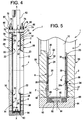
- each of the two Pivot 8 on its the passage 4 facing, inner side 20 a compressible bearing pre-seal 22 between the shaft 10 and the housing second having.
- this has each Lagerervorabdichtung 22 a two-piece bearing bushing 24 with a shaft 10 receiving directly superimposed Inner bush 26 and one receiving the inner bush 26 and in the respective Bearing bore 16 of the housing 2 seated external socket 28.
- These two sockets 26, 28 are seated in each other so that they are axially against each other.
- each inner side 20 of the pivot bearing 8 is axially between the inner sleeve 26 and a projecting, radially inwardly beyond the front end of the inner sleeve 26th projecting, annular web-shaped end portion 30 of the outer sleeve 28 (see Fig. 5) a verpreßbares sealing element 32 arranged such that by an axial compression or bracing the bearing bush 24 - increment. the inner and outer bushings 26, 28th relative to each other - the sealing element 32 also radially between the outer sleeve 28th and the shaft 10 is pressed.
- the annular gap between the shaft 10th and the bearing bush 24 sealed to the side of the passage 4, so that an intrusion prevents the respective medium in the annular gap surrounding the shaft 10 becomes.
- each pivot bearing 8 is also removed on its from the passage 4 lying side 34, a second, outer sealing element 36 such that this second Sealing element 36 by the above-described axial compression of the Bearing 24 also radially outward against the bearing bore 16 of the housing. 2 is pressed.
- the sealing element 36 is seated axially between the outer sleeve 28 and a radially outwardly beyond the front end of the outer sleeve 28 projecting portion 37 of the inner sleeve 26 or a separate pressure bush 26a.
- At least the first, inner sealing element 32 is each Lagerervorabdichtung 22 by a sealing ring package with at least two formed compressible sealing rings 38.
- the two inner sealing elements 32 are preferably made of a three-piece sealing ring package of three compressible sealing rings 38, which are preferably pre-pressed Pure graphite rings acts.
- Each outer sealing element 36 is preferably made a similar sealing ring package of three sealing rings 38th
- the housing-side sealing seat 14 and the sealing zone 12 of the valve disc 6 are tapered "conically” in at least a portion of their circumference in adaptation to the closing pivoting movement of the valve disc 6 formed so that the free flow cross-section in the region of the sealing seat 14, in particular in the direction of the shaft side of the valve disc 6 slightly opposite direction.
- the shaft side of the flap disk 6 is the "pressure side”, which can be acted upon by a pressure p 1 .
- the opposite, facing away from the shaft 10 side of the valve disc 6 is the so-called “back pressure side”, which is acted upon by a pressure p 2 .
- the sealing zone 12 of the valve disc 6 is formed by a separate sealing ring 42, which is shown separately in Fig. 7.
- This sealing ring 42 is held clamped between a base plate 44 of the valve disc 6 and a particular disk-shaped, but possibly also annular disc-shaped clamping element 46 (see Fig. 3 and 6).
- the sealing ring 42 as a lamellar seal consists of several packet-like superimposed individual disks 42a, 42b made of steel (stainless steel).
- the first individual disk 42b of the disk seal 42 arranged on one side, in particular the pressure side p 1 has a thickness D 1 which is greater than the thickness D 2 of the remaining individual disks 42a - see
- the thickness D 1 of the first disc 42b is about 1 mm
- the thickness D 2 of all the remaining discs 42a is about 0.5 mm, for example.
- the individual disks 42a, b are internal Peripheral region of the sealing ring 42 at preferably at least three of the Ring circumference evenly distributed joints 50 cohesively with each other connected, in particular welded.
- this is in each case formed by two-sided incisions 52 approximately radially arranged tongues 54, wherein the welding takes place only in the region of the tongues 54 to thermally induced Avoid deformations of the discs.
- the individual disks 42a, b be pinned or riveted together in their annular area.
- the housing 2 is substantially hollow cylindrical or due to a relatively short flow length is formed approximately annular disc-shaped.
- the housing 2 has two frontal, opposite sealing surfaces 56, the with corresponding mating surfaces of certain, not shown Pressure system components, such as pipelines, pressure vessels, boilers, turbines and like, are flangeable.
- each is Lagervorabdichtung 22 by spring means 60 so permanently in the axial direction
- Spring force F urges that a permanent, self-adjusting radial Compression is achieved.
- the shaft 10 is one-sided with a Operating end 62 out of the housing 2 to the outside. On the other side ends the Shaft 10 in a sealed over a cover member 64 housing space.
- the cover member 64 is screwed flush against a housing surface 66, namely about, for example, four in Fig. 4 and 5 unrecognizable screw.
- the Sealing takes place via a sealing ring 68, preferably as so-called Spiral lid gasket made of graphite and in an annular recess in particular of the cover element 64 is arranged.
- the actuation end 62 of the shaft 10 closest (upper) bearing pre-seal 22 is a sleeve-shaped, the shaft 10 enclosing and partially in the housing 2 engaging stuffing box element 70 with the spring force F applied.
- the gland member 70 acts against the Inner bush 26 of the two-part bushing 24, in particular via a additional seal pack 72, which in the annular gap directly between the shaft 10th and the bearing bore 16 is seated, and preferably via a separate pressure bush 26 a.
- the stuffing box element 70 is acted upon by a pressure body 74, the outside of the housing 2 connected to the housing 2 to the shaft 10th parallel stud 76 is seated.
- the pressure body 74 has a central opening for the Wave 10 on.
- each stud 76 between the Pressure element 74 and a housing 2 opposite abutment element 78 at least one compression spring element 80, which for generating the for Preloading required, relatively high spring force F in particular as an off a plurality of disc springs existing spring package is formed.
- the Stud 76 as a screw threaded bolt and the abutment elements 78 as to suitable ringmuttem be formed.
- the spring preload F be preset.
- four studs 76 with corresponding compression spring elements 80 and abutment elements 78 in one force-symmetrical distribution around the shaft 10 around.
- Fig. 5 is the other, arranged on the closed side of the housing 2
- Bearing pre-seal 22 of at least one as a spring means 60 between the Cover member 64 and the inner sleeve 26 of the two-part bearing bushing 24 act Compressed spring 82 acted upon.
- this compression spring 82 is preferred around a spring plate consisting of several disc springs to the required, right high bias spring force F can apply.
- the compression spring 82 is seated in an inner receiving recess 84 of the cover member 64 and acts in particular via a disc-shaped pressure element 86 on the bearing bush 24 or over the preferably existing pressure bushing 26a on the inner sleeve 26.
- the pressure element 86 can sit with advantage without play in a recess of the cover member 64 and while a substantially play in the bearing bush engaging centering approach 88 have. As a result, an automatic centering of the Cover element 64 is achieved relative to the housing 2.
- the invention is not limited to the illustrated and described embodiments limited, but also includes all the same in the context of the invention Versions. Furthermore, the invention has hitherto also not yet been claimed in claim 1 defined feature combination limited, but can also by any arbitrary other combination of certain features of all individual features disclosed be defined. This means that basically every single feature of claim 1 omitted or by at least one to another Site of the application disclosed individual feature can be replaced. Insofar is the Claim 1 merely as a first formulation attempt for an invention understand.
Description
Die vorliegende Erfindung betrifft ein Klappenscheibenventil für Medien unter
Hochdruck und/oder Hochtemperatur, gemäß dem Oberbegriff des Patentanspruchs 1.The present invention relates to a disc valve for media under
High pressure and / or high temperature, according to the preamble of
Derartige Ventile werden als Absperrorgane in Hochdrucksystemen, beispielsweise zwischen Rohrleitungen, Druckbehältern, Kesseln, Turbinen und/oder dergleichen, eingesetzt. Dabei sind üblicherweise eine umfängliche Dichtzone der Klappenscheibe und der umfangsgemäße gehäuseseitige Dichtsitz in Anpassung an die Schließ- bzw. Öffnungsbewegung der Klappenscheibe derart "konisch" ausgebildet, daß in der Absperrstellung im Falle einer Druckbeaufschlagung von der Seite her, auf der die Welle verläuft, die Klappenscheibe fest in den Dichtsitz gepreßt wird. Hierdurch wird auch bei einem sehr hohen Druck eine effektive Abdichtung gewährleistet, und gleichzeitig wird die Klappenscheibe auch mechanisch gegen den Druck abgestützt. In der Praxis sind solche Ventile aber in der Regel für beide Fließrichtungen ausgelegt, so daß oft auch der umgekehrte Belastungsfall auftritt, wobei die Klappenscheibe auf ihrer der Welle abgekehrten Seite mit einem Gegendruck beaufschlagt wird.Such valves are used as shut-off valves in high-pressure systems, for example between pipelines, pressure vessels, boilers, turbines and / or the like, used. In this case, usually a circumferential sealing zone of the valve disc and the circumferential housing-side sealing seat in adaptation to the closing or Opening movement of the valve disc so "conical" formed that in the shut-off position in the case of pressurization from the side on which the shaft runs, the disc is pressed firmly into the sealing seat. This will also ensures effective sealing at a very high pressure, and at the same time the disc is also mechanically supported against the pressure. In practice However, such valves are usually designed for both flow directions, so often also the reverse load case occurs, the disc on her the Wave remote side is acted upon by a back pressure.
Bei früheren bekannten Ventilen hat sich im praktischen Einsatz gezeigt, daß es bei bestimmten Medien zu Funktionsstörungen dahingehend kommen kann, daß nach einer bestimmten Zeit die Klappenscheibe kaum noch oder sogar überhaupt nicht mehr betätigt werden kann.In prior known valves has been shown in practice that it is at certain media to malfunction may come to the effect that after a certain time the disc hardly or even not at all can be operated.
Bei einem in dem Dokument DE-U- 298 22 791 beschriebenen Klappenscheibenventil ist deshalb vorgesehen, daß jedes der beiden gehäuseseitigen Drehlager in seinem dem Durchlaß zugekehrten, inneren Endbereich eine statisch verpresste Lagervorabdichtung zwischen der Welle und dem Gehäuse aufweist. Hierdurch soll vermieden werden, daß das unter Druck stehende jeweilige Medium vom Durchlaß in den Bereich der Drehlager, d.h. jeweils in einen Ringspalt zwischen der Welle und einer gehäuseseitigen Lagerbohrung, eindringen kann. Diese Maßnahme beruhte auf der Erkenntnis, daß gerade ein solches Eindringen bestimmter Medien in den Bereich der Drehlager die beschriebenen Probleme verursacht. Vor allem polymerisierende Medien (sogenannte "Crack-Medien"), wie z.B. Hydrokarbon und bestimmte Harze, können Ablagerungen insbesondere in Form von Kristallen verursachen und damit zu einem Festfressen der Welle in den Drehlagem führen. Dies soll durch die Lagervorabdichtung verhindert werden, indem die Medien gar nicht erst in den Bereich der Drehlager eindringen können. Es hat sich aber gezeigt, dass nach längeren Einsatzzeiten doch noch solche Probleme auftreten können, weil es durch die Materialeigenschaften der im Bereich der Lagervorabdichtungen eingesetzten Graphitdichtringe und/oder (Kohle-) Fasergeflechtringe nach längerem Einsatz unter Hochdruck und/oder Hochtemperatur zu Setzungserscheinungen derart kommen kann, daß eine dort vorgesehene, statische, über Verschraubungen einmal vorgegebene Dichtungsverpressung nachlassen kann. Bei dem bekannten Klappscheibenventil kann zwar grundsätzlich die dem Wellen-Betätigungsende nächstliegende Lagervorabdichtung über Verschraubungen nachgespannt werden. Allerdings erfordert dies einerseits Wartungsarbeiten, deren Notwendigkeit aber von außen gar nicht erkannt werden kann, und andererseits ist die andere Lagervorabdichtung ausschließlich statisch über einen Gehäusedeckel verspannt und daher auch durch eine Wartung überhaupt nicht nachspannbar. Daraus kann eine Undichtigkeit beider Lagervorabdichtungen, insbesondere aber der vom Wellen-Betätigungsende entfernt liegenden Lagervorabdichtung, resultieren, wodurch das jeweilige Medium doch wieder in den Drehlagerbereich eindringen und die eingangs beschriebenen Probleme verursachen kann.In a valve disc valve described in the document DE-U-298 22 791 is therefore intended that each of the two housing-side pivot bearing in his the passage facing, inner end portion of a statically compressed Has bearing pre-seal between the shaft and the housing. This is intended be avoided that the pressurized respective medium from the passage in the range of pivot bearings, i. each in an annular gap between the shaft and a housing-side bearing bore, can penetrate. This measure was based on The realization that just such an intrusion of certain media in the field the pivot bearing causes the problems described. Especially polymerizing Media (so-called "crack media"), e.g. Hydrocarbon and certain resins, can cause deposits especially in the form of crystals and thus too a seizure of the shaft in the Drehlagem lead. This should be done by the Bearing pre-seal can be prevented by placing the media not even in the area the pivot bearing can penetrate. However, it has been shown that after longer Operation times still such problems can occur because it is due to the Material properties of the used in the field of bearing pre-seals Graphite sealing rings and / or (carbon) Fasergeflechtringe after prolonged use under High pressure and / or high temperature subsidence may occur in such a way that one provided there, static, once given by glands Sealing compression can subside. In the known flap valve can Although basically the closest to the shaft actuation end Retaining bearing preload be tightened by means of screwed connections. However requires on the one hand maintenance work, but their need from the outside not at all can be recognized, and on the other hand, the other bearing pre-seal only statically clamped on a housing cover and therefore also by a maintenance can not be re-tensioned at all. This can be a leak both Lagerervorabdichtungen, but in particular away from the shaft actuating end lying bearing pre-seal, resulting in the respective medium but again penetrate into the pivot bearing area and the problems described above can cause.
Ein Klappenscheibenventil der gattungsgemäßen, dem Oberbegriff des
Patentanspruchs 1 entsprechenden Art ist in dem Dokument US-A-2 835 268
beschrieben. Dabei sitzt jeweils ein verpressbarer Dichtring axial zwischen zwei Ring-
bzw. Buchsenelementen und radial direkt zwischen der Welle und einer Lageröffnung
des Gehäuses. Daraus können Probleme bei der Montage resultieren.A butterfly valve of the generic, the preamble of
Entsprechendes gilt auch für weitere Ventile, wie sie aus der JP 2000 046 200, der
US-A-4 758 530 bzw. der DE 1 179 049 bekannt sind.The same applies to other valves, as described in JP 2000 046 200, the
US-A-4 758 530 and
Der vorliegenden Erfindung liegt die Aufgabe zugrunde, ein Klappenscheibenventil der gattungsgemäßen Art weitergehend so zu verbessern, daß einerseits auch nach längerer Einsatzzeit sowie auch bei Verwendung für beliebige Medien stets eine störungsfreie Funktion zum Öffnen und Schließen des Durchlasses gewährleistet und andererseits das Ventil auch mit konstruktiv einfacher Ausgestaltung einfach und schnell montiert werden kann.The present invention has for its object, a butterfly valve of the generic type to continue to improve so that on the one hand also after longer service life as well as when used for any media always one trouble-free function to open and close the passage ensures and On the other hand, the valve with a structurally simple design easy and can be mounted quickly.
Erfindungsgemäß wird dies durch die Merkmale des Patentanspruchs 1 erreicht.
Vorteilhafte Ausgestaltungsmerkmale sind Gegenstand der abhängigen Ansprüche.This is achieved by the features of
Zumindest die von dem Betätigungsende der Welle entfernt liegende Lagervorabdichtung ist über Spannmittel derart axial mit einer Nachspannkraft beaufschlagbar, dass eine nachstellende radiale Verpressbarkeit erreicht wird. Vorzugsweise ist auch die andere, dem Betätigungsende der Welle nächst liegende Lagervorabdichtung über Spannmittel zum Nachspannen beaufschlagbar. Hierbei ist es besonders vorteilhaft, die Spannmittel durch Federmittel derart zu bilden, dass die bzw. jede Lagervorabdichtung in axialer Richtung permanent mit Federkraft beaufschlagt ist, so dass eine dauerhafte selbstnachstellende radiale Verpressung erreicht wird. At least the remote from the operating end of the shaft Lagerervorabdichtung is about clamping means so axially with a Nachspannkraft acted upon that an adjusting radial compressibility is achieved. Preferably, the other, the operating end of the shaft closest Bearing pre-seal can be acted upon by clamping means for retightening. Here is It is particularly advantageous to form the clamping means by spring means such that the or each Lagerervorabdichtung in the axial direction permanently with spring force is applied, so that a permanent self-adjusting radial compression is reached.
Bevorzugt sind somit beide Lagervorabdichtungen wenigstens durch Wartungsarbeiten nachspannbar. In der bevorzugten Ausgestaltung, wobei als Spannmittel Federmittel vorgesehen sind, wird vorteilhafterweise eine automatische Selbstnachstellung der Dichtungsverpressung erreicht, indem die Federmittel die Lagervorabdichtungen stets mit nahezu konstanter Federkraft beaufschlagen und so dauerhaft verspannen. Dadurch wird ein praktisch wartungsfreies Klappenscheibenventil mit langer Gebrauchszeit geschaffen. Zusätzlich tritt der weitere Vorteil auf, daß durch die über lange Zeit hinweg aufrechterhaltene Lagervorabdichtung auch eine druckbedingte axiale Kraftbeaufschlagung der Welle vermieden wird, weil das Druckmedium von einem Raum ferngehalten wird, in dem das einem Betätigungsende gegenüberliegende Ende der Welle praktisch gekapselt angeordnet ist; dieser Raum bleibt durch die effektive, selbstnachstellende Lagervorabdichtung vorteilhafterweise druckfrei.Thus, both are preferred Bearing pre-seals at least re-tensioned by maintenance. In the preferred embodiment, being provided as a clamping means spring means is advantageously an automatic self-adjustment of the seal compression achieved by the spring means the Lagerervorabdichtungen always with almost constant Apply spring force and thus permanently clamp. This will be a practical Maintenance-free flap valve created with long service life. additionally the further advantage arises that is maintained by the over long time Lagerervorabdichtung also a pressure-induced axial application of force to the shaft is avoided because the pressure medium is kept away from a room in which the end of the shaft opposite an operating end is practically encapsulated is arranged; this space remains through the effective, self-adjusting Bearing pre-seal advantageously pressure-free.
Gemäß der Erfindung ist vorgesehen, daß jede Lagervorabdichtung eine zweiteilige Lagerbuchse mit einer die Welle unmittelbar aufnehmenden Innenbuchse und einer die Innenbuchse aufnehmenden und in einer Lagerbohrung des Gehäuses sitzenden Außenbuchse aufweist. Hierbei ist im inneren, d.h. dem Durchlaß zugekehrten Endbereich des jeweiligen Drehlagers axial zwischen der Innenbuchse und einem vorspringenden, ringstegförmigen Endabschnitt der Außenbuchse ein verpreßbares Dichtelement derart angeordnet, daß durch das axiale Verpressen der Lagerbuchse - bzw. der Innenbuchse und der Außenbuchse relativ zueinander - durch die erfindungsgemäße Federkraft das Dichtelement auch radial dauerhaft nach innen gegen die Welle verpreßt wird. Diese bevorzugte Ausgestaltung stellt einen besonderen Vorteil hinsichtlich der Montage des Klappenscheibenventils dar. Die Welle kann zunächst problemlos in den - bevorzugt von den jeweils zweiteiligen Lagerbuchsen gebildeten - Drehlagem durch einfaches Einschieben montiert werden. Erst nach diesem Zusammensetzen werden dann die Lagervorabdichtungen durch axiales Verpressen der Lagerbuchsen durch die Federmittel verspannt. According to the invention it is provided that each Bearing pre-seal a two-piece bearing bush with a shaft directly receiving inner bush and one receiving the inner bush and in one Bearing bore of the housing sitting outer sleeve. Here is inside, i.e. the passage facing the end portion of the respective rotary bearing axially between the inner bush and a projecting, annular web-shaped end portion of the External bushing a verpreßbares sealing element arranged such that by the axial Pressing the bushing - or the inner sleeve and the outer sleeve relative to each other - by the spring force of the invention, the sealing element also radially permanently pressed inwards against the shaft. This preferred embodiment represents a particular advantage with regard to the assembly of the valve disc valve The wave can initially easily in the - preferably of each Two-piece bushings formed - Drehlagem by simply pushing to be assembled. Only after this composition then the Lagerervorabdichtungen by axial compression of the bushings by the Spring means braced.
Anhand eines bevorzugten, in der Zeichnung dargestellten Ausführungsbeispiels soll im folgenden die Erfindung näher erläutert werden. Dabei zeigen:
- Fig. 1
- eine Vorderansicht eines erfindungsgemäßen Klappenscheibenventils in Absperrstellung auf die "Gegendruckseite",
- Fig. 2
- einen Axialschnitt in der Schnittebene II-II gemäß Fig. 1, wobei hier eine herkömmliche, bekannte Ausführungsform veranschaulicht ist,
- Fig. 3
- eine gesonderte und vergrößerte Darstellung der Klappenscheibe in Axialrichtung, d.h. in Pfeilrichtung III gemäß Fig. 1,
- Fig. 4
- eine vereinfachte und vergrößerte Darstellung analog zu Fig. 2 in einer erfindungsgemäßen Ausführungsform,
- Fig. 5
- eine Ausschnittvergrößerung des Bereichs des unteren Drehlagers aus Fig. 4,
- Fig. 6
- eine vergrößerte Detailansicht des Bereichs VI in Fig. 3 und
- Fig. 7
- eine gesonderte Darstellung eines Dichtungsringes der Klappenscheibe in Pfeilrichtung VII gemäß Fig. 3.
- Fig. 1
- a front view of a valve disc valve according to the invention in shut-off position on the "counter-pressure side",
- Fig. 2
- an axial section in the sectional plane II-II of FIG. 1, wherein a conventional, known embodiment is illustrated here,
- Fig. 3
- a separate and enlarged view of the disc in the axial direction, ie in the direction of arrow III of FIG. 1,
- Fig. 4
- a simplified and enlarged view similar to FIG. 2 in an embodiment according to the invention,
- Fig. 5
- a detail enlargement of the area of the lower pivot bearing of FIG. 4,
- Fig. 6
- an enlarged detail view of the area VI in Fig. 3 and
- Fig. 7
- a separate representation of a sealing ring of the disc in the direction of arrow VII of FIG. 3rd
In den verschiedenen Figuren der Zeichnung sind gleiche Teile stets mit den gleichen Bezugszeichen versehen und werden daher in der Regel auch jeweils nur einmal beschrieben. In the various figures of the drawing, like parts are always the same Reference numerals provided and therefore usually only once in each case described.
Ein erfindungsgemäßes Klappenscheibenventil 1 besteht aus einem Gehäuse 2 mit
einem Durchlaß 4 (vgl. Fig. 2 und 4) für ein Medium sowie aus einer als Absperrorgan
innerhalb des Durchlasses 4 angeordneten, im wesentlichen kreisförmigen
Klappenscheibe 6. Diese Klappenscheibe 6 ist über eine auf einer Scheibenseite
angeordnete, beidendig in gehäuseseitigen Drehlagem 8 geführte und sich quer durch
den Durchlaß 4 erstreckende Welle 10 um eine bezüglich ihrer Kreisform im
wesentlichen diametral verlaufende Drehachse X-X derart verdrehbar bzw. - zutreffender
gesagt - verschwenkbar, daß sie in einer Öffnungsstellung (in der Zeichnung nicht
dargestellt) mit ihrer Scheibenebene etwa entsprechend der Durchlaßrichtung bzw.
etwa parallel dazu verläuft und in der in Fig. 1 und 2 dargestellten, quer zur
Durchlaßrichtung stehenden Absperrstellung den Durchlaß 4 verschließend mit einer
äußeren umfangsgemäßen Dichtzone 12 dichtend mit einem gehäuseseitigen
umfangsgemäßen Dichtsitz 14 zusammenwirkt. Dies ist am besten in Fig. 2 zu
erkennen.An
Bei der in Fig. 2 veranschaulichten, herkömmlichen Ausführungsform ist erkennbar,
daß im Bereich jedes Drehlagers 8 jeweils zwischen der Welle 10 und einer
zugehörigen Lagerbohrung 16 ein Ringspalt 18 gebildet ist, in den ein unter Druck
stehendes Medium aus dem Bereich des Durchlasses 4 eindringen und sich dort
eventuell festsetzen könnte.In the illustrated in Fig. 2, the conventional embodiment can be seen
that in the region of each pivot bearing 8 each between the
Um dies zu vermeiden, ist gemäß Fig. 4 und 5 vorgesehen, daß jedes der beiden
Drehlager 8 auf seiner dem Durchlaß 4 zugekehrten, inneren Seite 20 eine
verpreßbare Lagervorabdichtung 22 zwischen der Welle 10 und dem Gehäuse 2
aufweist. Zweckmäßigerweise besitzt hierzu jede Lagervorabdichtung 22 eine
zweiteilige Lagerbuchse 24 mit einer die Welle 10 unmittelbar lagernd aufnehmenden
Innenbuchse 26 und einer die Innenbuchse 26 aufnehmenden und in der jeweiligen
Lagerbohrung 16 des Gehäuses 2 sitzenden Außenbuchse 28. Diese beiden Buchsen
26, 28 sitzen so ineinander, daß sie axial gegeneinander verschiebbar sind. Auf der
jeweils inneren Seite 20 der Drehlager 8 ist axial zwischen der Innenbuchse 26 und
einem vorspringenden, radial nach innen über das Stirnende der Innenbuchse 26
ragenden, ringstegförmigen Endabschnitt 30 der Außenbuchse 28 (siehe Fig. 5) ein
verpreßbares Dichtelement 32 derart angeordnet, daß durch ein axiales Verpressen
bzw. Verspannen der Lagerbuchse 24 -bzw. der Innen- und Außenbuchsen 26, 28
relativ zueinander - das Dichtelement 32 auch radial zwischen der Außenbuchse 28
und der Welle 10 verpreßt wird. Hierdurch wird der Ringspalt zwischen der Welle 10
und der Lagerbuchse 24 zur Seite des Durchlasses 4 hin abgedichtet, so daß ein Eindringen
des jeweiligen Mediums in den die Welle 10 umgebenden Ringspalt verhindert
wird.To avoid this, it is provided according to FIGS. 4 and 5 that each of the two
Bevorzugt weist jedes Drehlager 8 auch auf seiner von dem Durchlaß 4 entfernt
liegenden Seite 34 ein zweites, äußeres Dichtelement 36 derart auf, daß dieses zweite
Dichtelement 36 durch das oben schon beschriebene axiale Verpressen der
Lagerbuchse 24 auch radial nach außen gegen die Lagerbohrung 16 des Gehäuses 2
verpreßt wird. Dazu sitzt das Dichtelement 36 axial zwischen der Außenbuchse 28 und
einem radial nach außen über das Stirnende der Außenbuchse 28 ragenden Abschnitt
37 der Innenbuchse 26 oder einer separaten Druckbuchse 26a.Preferably, each pivot bearing 8 is also removed on its from the passage 4
lying
Wie am besten in Fig. 5 erkennbar ist, ist zumindest das erste, innere Dichtelement 32
jeder Lagervorabdichtung 22 durch ein Dichtringpaket mit mindestens zwei
verpressbaren Dichtringen 38 gebildet. Insbesondere die beiden inneren Dichtelemente
32 bestehen vorzugsweise aus einem dreiteiligen Dichtringpaket aus drei
verpressbaren Dichtringen 38, bei denen es sich bevorzugt um vorgepresste
Reingraphitringe handelt. Jedes äußere Dichtelement 36 besteht vorzugsweise aus
einem gleichartigen Dichtringpaket aus drei Dichtringen 38.As best seen in FIG. 5, at least the first,
Wie sich nun weiterhin insbesondere aus Fig. 2, 3, 6 und 7 ergibt, sind der
gehäuseseitige Dichtsitz 14 und die Dichtzone 12 der Klappenscheibe 6 zumindest in
einem Teilbereich ihres Umfanges in Anpassung an die Schließ-Schwenkbewegung
der Klappenscheibe 6 derart "konisch" abgeschrägt ausgebildet, daß sich der freie
Strömungsquerschnitt im Bereich des Dichtsitzes 14 insbesondere in die der
Wellenseite der Klappenscheibe 6 gegenüberliegende Richtung geringfügig verringert.
Hierdurch handelt es sich bei der Wellenseite der Klappenscheibe 6 um die
"Druckseite", die mit einem Druck p1 beaufschlagbar ist. Die gegenüberliegende, von
der Welle 10 abgekehrte Seite der Klappenscheibe 6 ist die sogenannte
"Gegendruckseite", die mit einem Druck p2 beaufschlagbar ist. Bei Beaufschlagung mit
Druck p1 - bzw. wenn p1 größer p2 - wird die Klappenscheibe 6 in den Dichtsitz 14
gepreßt. Bei Beaufschlagung mit hohem Gegendruck p2 (bzw. p2 größer p1) wird die
Klappenscheibe 6 über die Welle 10 gegen Abheben von dem Dichtsitz 14 abgestützt.As further follows, in particular from FIGS. 2, 3, 6 and 7, the housing-
Die Dichtzone 12 der Klappenscheibe 6 ist von einem separaten Dichtungsring 42
gebildet, der gesondert in Fig. 7 dargestellt ist. Dieser Dichtungsring 42 ist zwischen
einer Basisscheibe 44 der Klappenscheibe 6 und einem insbesondere
scheibenförmigen, gegebenenfalls aber auch ringscheibenförmigen Klemmelement 46
eingespannt gehalten (s. hierzu Fig. 3 und 6). Hierbei ist nun bevorzugt vorgesehen,
daß der Dichtungsring 42 als Lamellendichtung aus mehreren paketartig
aufeinanderliegenden Einzelscheiben 42a, 42b aus Stahl (Edelstahl) besteht.
Bezüglich der oben beschriebenen Druckverhältnisse ist es hierbei vorteilhaft, wenn
die auf einer Seite, insbesondere der Druckseite p1, angeordnete erste Einzelscheibe
42b der Lamellendichtung 42 eine Dicke D1 aufweist, die größer als die Dicke D2 der
übrigen Einzelscheiben 42a ist - siehe hierzu Fig. 6. Beispielsweise beträgt die Dicke
D1 der ersten Scheibe 42b etwa 1 mm, während die Dicke D2 aller übrigen Scheiben
42a z.B. etwa 0,5 mm beträgt.The sealing
Wie sich noch aus Fig. 7 ergibt, sind die Einzelscheiben 42a, b im inneren
Umfangsbereich des Dichtungsrings 42 an vorzugsweise mindestens drei über den
Ringumfang gleichmäßig verteilten Verbindungsstellen 50 stoffschlüssig miteinander
verbunden, und zwar insbesondere verschweißt. Vorzugsweise sind hierzu jeweils
durch beidseitige Einschnitte 52 etwa radial angeordnete Zungen 54 gebildet, wobei
die Verschweißung nur im Bereich der Zungen 54 erfolgt, um thermisch bedingte
Verformungen der Scheiben zu vermeiden.As can be seen from FIG. 7, the
In einer nicht dargestellten Ausführungsvariante können die Einzelscheiben 42a, b
auch in ihrem Ringflächenbereich miteinander verstiftet bzw. vernietet sein.In an embodiment not shown, the
In jedem Fall ist darauf zu achten, daß die beiden Ring-Stirnflächen plan bearbeitet
sind, um sie zwischen Basisscheibe und Klemmelement 46 einspannen zu können.In any case, make sure that the two ring end faces machined plan
are to clamp them between the base plate and clamping
Ergänzend sei noch erwähnt, daß das Gehäuse 2 im wesentlichen hohlzylindrisch bzw.
aufgrund relativ kurzer Strömungslänge etwa ringscheibenförmig ausgebildet ist.
Hierbei weist das Gehäuse 2 zwei stirnseitige, gegenüberliegende Dichtflächen 56 auf,
die mit entsprechenden Gegendichtflächen von bestimmten, nicht dargestellten
Drucksystemkomponenten, wie Rohrleitungen, Druckbehältern, Kesseln, Turbinen und
dergleichen, verflanschbar sind.In addition, it should be mentioned that the
In der dargestellten, bevorzugten Ausführung der Erfindung ist jede Lagervorabdichtung 22 durch Federmittel 60 derart in axialer Richtung permanent mit Federkraft F beaufschlagt, daß eine dauerhafte, selbstnachstellende radiale Verpressung erreicht wird.In the illustrated preferred embodiment of the invention, each is Lagervorabdichtung 22 by spring means 60 so permanently in the axial direction Spring force F urges that a permanent, self-adjusting radial Compression is achieved.
Bei der dargestellten Ausführungsform ist die Welle 10 einseitig mit einem
Betätigungsende 62 aus dem Gehäuse 2 nach außen geführt. Anderseitig endet die
Welle 10 in einem über ein Deckelelement 64 dicht verschlossenen Gehäuseraum.
Das Deckelelement 64 ist plan gegen eine Gehäusefläche 66 verschraubt, und zwar
über beispielsweise vier in Fig. 4 und 5 nicht erkennbare Schraubelemente. Die
Abdichtung erfolgt über einen Dichtring 68, der bevorzugt als sogenannte
Spiraldeckeldichtung aus Graphit gebildet und in einer ringförmigen Vertiefung
insbesondere des Deckelelementes 64 angeordnet ist. In the illustrated embodiment, the
Die dem Betätigungsende 62 der Welle 10 nächstliegende (obere) Lagervorabdichtung
22 wird über ein hülsenförmiges, die Welle 10 umschließendes und bereichsweise in
das Gehäuse 2 eingreifendes Stopfbuchsenelement 70 mit der Federkraft F
beaufschlagt. Vorzugsweise wirkt das Stopfbuchsenelement 70 gegen die
Innenbuchse 26 der zweiteiligen Lagerbuchse 24, und zwar insbesondere über eine
zusätzliche Dichtungspackung 72, die im Ringspalt unmittelbar zwischen der Welle 10
und der Lagerbohrung 16 sitzt, sowie bevorzugt über eine separate Druckbuchse 26 a.
Dabei wird das Stopfbuchsenelement 70 von einem Druckkörper 74 beaufschlagt, der
außerhalb des Gehäuses 2 auf mit dem Gehäuse 2 verbundenen, zur Welle 10
parallelen Stehbolzen 76 sitzt. Der Druckkörper 74 weist eine mittige Öffnung für die
Welle 10 auf. Als Federmittel 60 sitzt auf jedem Stehbolzen 76 zwischen dem
Druckkörper 74 und einem dem Gehäuse 2 gegenüberliegenden Widerlagerelement
78 mindestens ein Druckfederelement 80, welches zur Erzeugung der zum
Vorspannen erforderlichen, relativ hohen Federkraft F insbesondere als ein aus
mehreren Tellerfedern bestehendes Federpaket ausgebildet ist. Mit Vorteil können die
Stehbolzen 76 als Schraubgewindebolzen und die Widerlagerelemente 78 als dazu
passende Schraubmuttem ausgebildet sein. Hierdurch kann die Federvorspannung F
voreingestellt werden. Zweckmäßigerweise sind vier Stehbolzen 76 mit
entsprechenden Druckfederelementen 80 und Widerlagerelementen 78 in einer
kraftsymmetrischen Verteilung um die Welle 10 herum vorgesehen.The
Wie sich am besten aus der vergrößerten Darstellung in Fig. 5 entnehmen läßt, wird
die andere, auf der verschlossenen Seite des Gehäuses 2 angeordnete
Lagervorabdichtung 22 von mindestens einer als Federmittel 60 zwischen dem
Deckelelement 64 und der Innenbuchse 26 der zweiteiligen Lagerbuchse 24 wirkenden
Druckfeder 82 beaufschlagt. Auch bei dieser Druckfeder 82 handelt es sich bevorzugt
um ein aus mehreren Tellerfedem bestehendes Federpaket, um die erforderliche, recht
hohe Vorspann-Federkraft F aufbringen zu können. Dabei sitzt die Druckfeder 82 in
einer inneren Aufnahmevertiefung 84 des Deckelelementes 64 und wirkt insbesondere
über ein scheibenförmiges Druckelement 86 auf die Lagerbuchse 24 bzw. über die
bevorzugt vorhandene Druckbuchse 26a auf die Innenbuchse 26. Das Druckelement
86 kann mit Vorteil spielfrei in einer Vertiefung des Deckelelementes 64 sitzen und
dabei einen im wesentlichen spielfrei in die Lagerbuchse eingreifenden Zentrieransatz
88 aufweisen. Dadurch wird bei der Montage eine selbsttätige Zentrierung des
Deckelelementes 64 relativ zum Gehäuse 2 erreicht.As can best be seen from the enlarged view in Fig. 5 is
the other, arranged on the closed side of the
Die Erfindung ist nicht auf die dargestellten und beschriebenen Ausführungsbeispiele
beschränkt, sondern umfaßt auch alle im Sinne der Erfindung gleichwirkenden
Ausführungen. Ferner ist die Erfindung bislang auch noch nicht auf die im Anspruch 1
definierte Merkmalskombination beschränkt, sondern kann auch durch jede beliebige
andere Kombination von bestimmten Merkmalen aller insgesamt offenbarten Einzelmerkmalen
definiert sein. Dies bedeutet, daß grundsätzlich praktisch jedes Einzelmerkmal
des Anspruchs 1 weggelassen bzw. durch mindestens ein an anderer
Stelle der Anmeldung offenbartes Einzelmerkmal ersetzt werden kann. Insofern ist der
Anspruch 1 lediglich als ein erster Formulierungsversuch für eine Erfindung zu
verstehen.The invention is not limited to the illustrated and described embodiments
limited, but also includes all the same in the context of the invention
Versions. Furthermore, the invention has hitherto also not yet been claimed in
Claims (17)
- Butterfly valve (1) for media under high pressure and/or at high temperature, consisting of a housing (2) with a passage (4) for the medium and of a butterfly (6) arranged as a shut-off member within the passage (4) and, via a shaft (10) guided at both ends in pivot bearings (8) on the housing, extending transversely through the passage (4) and guided on one side by an actuating end (62) out of the housing (2) to the exterior, pivotable about an axis (X-X) of rotation in such a way that, in an opened position, its disc plane extends approximately in the direction of the passage and in a closed position, lying transversely to the passage direction, it interacts with a sealing seat (14) on the housing to form a circumferential seal, an advance bearing seal (22) being arranged in front of each of the two pivot bearings (8) on its inner side (20) facing the passage (4) in such a way that an annular gap surrounding the shaft (10) in the region of the respective pivot bearing (8) is sealed off against penetration of medium from the passage (4) by means of a compressible sealing element (32),
it being possible for the advance bearing seal (22) lying remote from the actuating end (62) of the shaft (10) to be axially subjected via tensioning means to the effect of a retensioning force such that a subsequent radial compressibility is achieved characterized in that the advance bearing seal (22) has a two-part bearing bush (24) with an inner bush (26) receiving the shaft (10) and an outer bush (28) receiving the inner bush (26) and seated in a bearing hole (16) in the housing (2), the compressible sealing element (32) being arranged on the inner side (20) of the pivot bearing (8), axially between the inner bush (26) and a projecting end section (30) of the outer bush (28), so that, as a result of the axial compression of the bearing bush (24), the sealing element (32) is also radially compressed between the outer bush (28) and inwardly compressed against the shaft (10). - Butterfly valve according to Claim 1,
characterized in that the other advance bearing seal (22) lying closer to the shaft actuating end (62) can also be acted upon via tensioning means for retensioning. - Butterfly valve according to Claim 1 or 2,
characterized in that the tensioning means are formed by a spring means (60) in such a way that the respective advance bearing seal (22) is permanently subjected to the action of a spring force (F) in the axial direction and a continuous self-adjusting radial compression is achieved. - Butterfly valve according to one of Claims 1 to 3,
characterized in that the/each pivot bearing (8) has, on its side (34) remote from the passage (4), a second, external sealing element (36), so that this second sealing element (36), by axial compression of the bearing bush (24), is also radially compressed outward against the bearing aperture (16) in the housing (2). - Butterfly valve according to one of Claims 1 to 4,
characterized in that at least the first, inner sealing element (32) of the/each advance bearing seal (22) is formed by a gasket pack with at least two compressible gaskets (38) consisting, in particular, of pre-pressed pure graphite. - Butterfly valve according to one of Claims 1 to 5,
characterized in that the shaft (10) ends, on its side opposite the actuating end (62), in a housing space sealingly closed by a lid element (64). - Butterfly valve according to one of Claims 1 to 6,
characterized in that the advance bearing seal (22) lying closer to the actuating end (62) of the shaft (10) is subjected to the action of the tensioning means via a sleeve-shaped stuffing box element (70) enclosing the shaft (10) and, in particular, via an additional seal packing (72) and via the inner bush (26) of the bearing bush (24). - Butterfly valve according to Claim 7,
characterized in that the stuffing box element (70) is subjected to the action of a pressure member (74) which has an aperture through which the shaft (10) engages and is seated on the stud bolt (76) connected to the housing (2), at least one compression spring element (80), especially a spring assembly consisting of a plurality of disc springs, being seated on the stud bolt (76), in each case between the pressure member (74) and an abutment element (78), as a tensioning or spring means (60). - Butterfly valve according to Claim 8,
characterized in that the stud bolts (76) are designed as threaded bolts and the abutment elements (78) as threaded nuts. - Butterfly valve according to Claim 8 or 9,
characterized in that four stud bolts (78) are provided, with corresponding compression spring elements (80) and abutment elements (78), in a force-symmetrical arrangement. - Butterfly valve according to one of Claims 6 to 10,
characterized in that the advance bearing seal (22) arranged on the closed side of the housing (2) is subjected to the action of at least one compression spring (82), especially a spring assembly consisting of a plurality of disc springs, acting as a tensioning or spring means (60) between the lid element (64) and the inner bush (26) of the bearing bush (24). - Butterfly valve according to Claim 11,
characterized in that the compression spring (82) is seated in an inner receiving recess (84) of the lid element (64) and, in particular, acts on the bearing bush (24) via a discoid pressure element (86). - Butterfly valve according to one of Claims 1 to 12,
characterized in that the sealing zone (12) of the butterfly (6) is formed by a sealing ring (42), which is held by clamping between a base disc (44) of the butterfly (6) and a discoid or annular disc-shaped clamping element (46). - Butterfly valve according to Claim 13,
characterized in that the sealing ring (42) consists, as a segment seal, of individual steel discs (42a,b) placed one above the other as a pack. - Butterfly valve according to Claim 14,
characterized in that the individual discs (42a,b) are connected to each other by bonding, especially by welding, in the inner circumferential region of the sealing ring (42) at, preferably, at least three connection points (50). - Butterfly valve according to Claim 14,
characterized in that the individual discs (42a,b) are pinned or riveted together in their annular surface region. - Butterfly valve according to one of Claims 14 to 16,
characterized in that the first individual disc (42b) of the segment seal (42), arranged on one side, especially a pressure side, has a thickness (D1) which is greater than the thickness (D2) of the other individual discs (42a).
Applications Claiming Priority (2)
| Application Number | Priority Date | Filing Date | Title |
|---|---|---|---|
| US766508 | 2001-01-19 | ||
| US09/766,508 US6595488B2 (en) | 2001-01-19 | 2001-01-19 | Butterfly valve |
Publications (3)
| Publication Number | Publication Date |
|---|---|
| EP1233216A2 EP1233216A2 (en) | 2002-08-21 |
| EP1233216A3 EP1233216A3 (en) | 2003-05-21 |
| EP1233216B1 true EP1233216B1 (en) | 2005-03-02 |
Family
ID=25076644
Family Applications (1)
| Application Number | Title | Priority Date | Filing Date |
|---|---|---|---|
| EP01130786A Expired - Lifetime EP1233216B1 (en) | 2001-01-19 | 2001-12-22 | Butterfly valve |
Country Status (3)
| Country | Link |
|---|---|
| US (1) | US6595488B2 (en) |
| EP (1) | EP1233216B1 (en) |
| DE (1) | DE50105468D1 (en) |
Cited By (1)
| Publication number | Priority date | Publication date | Assignee | Title |
|---|---|---|---|---|
| DE102009017510A1 (en) | 2009-04-15 | 2010-10-28 | müller co-ax ag | Shut-off flap for controlling flow rate and/or flow velocity of e.g. liquid, in pipeline, has pretensionable bearing seal provided in housing between fluid to be controlled and bearings and sealing shaft and housing |
Families Citing this family (16)
| Publication number | Priority date | Publication date | Assignee | Title |
|---|---|---|---|---|
| DE10251179A1 (en) * | 2002-10-31 | 2004-05-13 | Siemens Ag | housing flange |
| DE10251385A1 (en) * | 2002-11-01 | 2004-05-13 | Siemens Ag | Valve |
| US7032883B2 (en) * | 2004-04-07 | 2006-04-25 | Hr Textron, Inc. | Hybrid butterfly fluid control valve |
| DE102004046077A1 (en) * | 2004-09-23 | 2006-04-06 | Pierburg Gmbh | Exhaust flap means |
| US20070080314A1 (en) * | 2005-10-06 | 2007-04-12 | Arvin Technologies, Inc. | Exhaust valve bushing |
| DE102007050899A1 (en) * | 2007-10-24 | 2009-04-30 | Continental Automotive Gmbh | Valve |
| EP2249067A1 (en) * | 2009-05-04 | 2010-11-10 | Johann Zwick | Flap disc valve |
| DE102010006023B4 (en) * | 2010-01-27 | 2012-04-26 | Pierburg Gmbh | Sealing arrangement for a control device of an internal combustion engine |
| CN105452745B (en) * | 2013-08-28 | 2019-03-19 | 博格华纳公司 | High-temperature valve sealing |
| EP3268596A1 (en) * | 2015-03-13 | 2018-01-17 | Sol Alva Mecânica de Precisão S.A. | GAS RECIRCULATION VALVE FROM - 40ºC TO 700ºC |
| US10844962B2 (en) * | 2015-10-07 | 2020-11-24 | Fisher Controls International Llc | Valve body insert apparatus and related methods |
| CN105202204A (en) * | 2015-10-12 | 2015-12-30 | 罗普阀业(宜兴)有限公司 | High-temperature butterfly valve for marine diesel engine |
| CN108291651B (en) | 2015-11-23 | 2020-11-27 | 维克托里克公司 | Valve and valve coupling with opposed tapered shafts |
| US9915352B2 (en) * | 2016-08-03 | 2018-03-13 | Scc, Inc. | Butterfly valve utilizing spring for consistent disk placement |
| US11391379B2 (en) | 2019-03-29 | 2022-07-19 | Velan Inc. | Butterfly valve and butterfly disc |
| CN113932019A (en) * | 2021-10-16 | 2022-01-14 | 东宝阀门有限公司 | High-pressure self-sealing butterfly valve |
Family Cites Families (10)
| Publication number | Priority date | Publication date | Assignee | Title |
|---|---|---|---|---|
| US2835268A (en) * | 1955-08-22 | 1958-05-20 | Clary Corp | Butterfly valve construction |
| DE1179049B (en) * | 1959-07-16 | 1964-10-01 | Zahnradfabrik Friedrichshafen | Exhaust engine brake, consisting of a brake flap, which has a through hole for receiving a flap shaft, and an undivided housing |
| US3778028A (en) * | 1972-08-02 | 1973-12-11 | Dore Co John L | Lined butterfly valve |
| US3905577A (en) * | 1973-03-08 | 1975-09-16 | Anchor Darling Valve Co | Valve |
| FR2255522B1 (en) * | 1973-12-19 | 1982-11-12 | Amri | |
| US4217923A (en) * | 1978-03-17 | 1980-08-19 | Kamyr Valves, Inc. | Ball valve with readily removable ball and seats for high temperature environment |
| FR2439348A1 (en) * | 1978-10-17 | 1980-05-16 | Gachot Jean | ANTI-FRICTION DEVICE FOR A VALVE CONTROL SHAFT |
| US4759530A (en) * | 1984-11-14 | 1988-07-26 | Neotecha Ag | Stem and disc seal construction for butterfly valves |
| JP3332861B2 (en) * | 1998-07-24 | 2002-10-07 | 株式会社巴技術研究所 | Butterfly valve |
| DE29822791U1 (en) | 1998-12-22 | 1999-04-08 | Zwick Armaturen Gmbh | Butterfly valve |
-
2001
- 2001-01-19 US US09/766,508 patent/US6595488B2/en not_active Expired - Lifetime
- 2001-12-22 EP EP01130786A patent/EP1233216B1/en not_active Expired - Lifetime
- 2001-12-22 DE DE50105468T patent/DE50105468D1/en not_active Expired - Lifetime
Cited By (1)
| Publication number | Priority date | Publication date | Assignee | Title |
|---|---|---|---|---|
| DE102009017510A1 (en) | 2009-04-15 | 2010-10-28 | müller co-ax ag | Shut-off flap for controlling flow rate and/or flow velocity of e.g. liquid, in pipeline, has pretensionable bearing seal provided in housing between fluid to be controlled and bearings and sealing shaft and housing |
Also Published As
| Publication number | Publication date |
|---|---|
| EP1233216A3 (en) | 2003-05-21 |
| US6595488B2 (en) | 2003-07-22 |
| DE50105468D1 (en) | 2005-04-07 |
| EP1233216A2 (en) | 2002-08-21 |
| US20020134960A1 (en) | 2002-09-26 |
Similar Documents
| Publication | Publication Date | Title |
|---|---|---|
| EP1233216B1 (en) | Butterfly valve | |
| EP0124821B1 (en) | Valve having a conical seat | |
| DE2941451C2 (en) | Low-friction seal for the actuator stem of taps and valves | |
| DE2430410A1 (en) | VALVE, IN PARTICULAR BALL VALVE | |
| DE3825116C2 (en) | ||
| DE3340231T1 (en) | Valve and spindle seal for it | |
| DE2445106A1 (en) | THROTTLE FLAP VALVE | |
| DE102015000846B4 (en) | Assembly unit for the axial clamping of rolling bearings on axles and shafts | |
| DE2125717C3 (en) | Stem and plug sealing for a ball valve | |
| EP0604608B1 (en) | Shut-off valve | |
| EP0658715B1 (en) | Flat-face threaded tube connector | |
| DE3841026A1 (en) | Shut-off fitting in a housing lined with plastic | |
| DE10342751B4 (en) | sealing arrangement | |
| DE2646781C3 (en) | Sealing system for switch shafts | |
| EP0260482B1 (en) | Cock with a cylindrical or conical plug | |
| DE102014103198B3 (en) | plug valve | |
| DE1032992B (en) | Shut-off valve with back seal | |
| DE3219309A1 (en) | VALVE WITH A VALVE CLOSURE | |
| EP0318737A2 (en) | Spherical cock | |
| DE4132709C2 (en) | Variable throttle valve | |
| DE2023073A1 (en) | Throttle valve | |
| EP1245878B1 (en) | Butterfly valve | |
| EP1039182B1 (en) | Seal device and seat valve | |
| DE2111059C3 (en) | Interception or quick-closing flap valve | |
| DE3801830C2 (en) |
Legal Events
| Date | Code | Title | Description |
|---|---|---|---|
| PUAI | Public reference made under article 153(3) epc to a published international application that has entered the european phase |
Free format text: ORIGINAL CODE: 0009012 |
|
| AK | Designated contracting states |
Kind code of ref document: A2 Designated state(s): AT BE CH CY DE DK ES FI FR GB GR IE IT LI LU MC NL PT SE TR |
|
| AX | Request for extension of the european patent |
Free format text: AL;LT;LV;MK;RO;SI |
|
| PUAL | Search report despatched |
Free format text: ORIGINAL CODE: 0009013 |
|
| RIC1 | Information provided on ipc code assigned before grant |
Ipc: 7F 16K 1/22 A Ipc: 7F 16K 1/226 B |
|
| AK | Designated contracting states |
Designated state(s): AT BE CH CY DE DK ES FI FR GB GR IE IT LI LU MC NL PT SE TR |
|
| AX | Request for extension of the european patent |
Extension state: AL LT LV MK RO SI |
|
| 17P | Request for examination filed |
Effective date: 20031117 |
|
| AKX | Designation fees paid |
Designated state(s): DE NL |
|
| 17Q | First examination report despatched |
Effective date: 20040310 |
|
| GRAP | Despatch of communication of intention to grant a patent |
Free format text: ORIGINAL CODE: EPIDOSNIGR1 |
|
| GRAS | Grant fee paid |
Free format text: ORIGINAL CODE: EPIDOSNIGR3 |
|
| GRAA | (expected) grant |
Free format text: ORIGINAL CODE: 0009210 |
|
| AK | Designated contracting states |
Kind code of ref document: B1 Designated state(s): DE NL |
|
| REG | Reference to a national code |
Ref country code: IE Ref legal event code: FG4D Free format text: GERMAN |
|
| REF | Corresponds to: |
Ref document number: 50105468 Country of ref document: DE Date of ref document: 20050407 Kind code of ref document: P |
|
| PLBE | No opposition filed within time limit |
Free format text: ORIGINAL CODE: 0009261 |
|
| STAA | Information on the status of an ep patent application or granted ep patent |
Free format text: STATUS: NO OPPOSITION FILED WITHIN TIME LIMIT |
|
| 26N | No opposition filed |
Effective date: 20051205 |
|
| REG | Reference to a national code |
Ref country code: DE Ref legal event code: R082 Ref document number: 50105468 Country of ref document: DE Representative=s name: PATENT- UND RECHTSANWAELTE DR. SOLF & ZAPF, DE Ref country code: DE Ref legal event code: R081 Ref document number: 50105468 Country of ref document: DE Owner name: ZWICK ARMATUREN GMBH, DE Free format text: FORMER OWNER: ZWICK GMBH, 58256 ENNEPETAL, DE |
|
| PGFP | Annual fee paid to national office [announced via postgrant information from national office to epo] |
Ref country code: NL Payment date: 20201223 Year of fee payment: 20 |
|
| PGFP | Annual fee paid to national office [announced via postgrant information from national office to epo] |
Ref country code: DE Payment date: 20210226 Year of fee payment: 20 |
|
| REG | Reference to a national code |
Ref country code: DE Ref legal event code: R071 Ref document number: 50105468 Country of ref document: DE Ref country code: NL Ref legal event code: MK Effective date: 20211221 |