EP1233093A1 - Sliderneedle - Google Patents
Sliderneedle Download PDFInfo
- Publication number
- EP1233093A1 EP1233093A1 EP02405107A EP02405107A EP1233093A1 EP 1233093 A1 EP1233093 A1 EP 1233093A1 EP 02405107 A EP02405107 A EP 02405107A EP 02405107 A EP02405107 A EP 02405107A EP 1233093 A1 EP1233093 A1 EP 1233093A1
- Authority
- EP
- European Patent Office
- Prior art keywords
- needle
- slide
- hook
- relative
- sliding
- Prior art date
- Legal status (The legal status is an assumption and is not a legal conclusion. Google has not performed a legal analysis and makes no representation as to the accuracy of the status listed.)
- Granted
Links
Images


Classifications
-
- D—TEXTILES; PAPER
- D04—BRAIDING; LACE-MAKING; KNITTING; TRIMMINGS; NON-WOVEN FABRICS
- D04B—KNITTING
- D04B35/00—Details of, or auxiliary devices incorporated in, knitting machines, not otherwise provided for
- D04B35/02—Knitting tools or instruments not provided for in group D04B15/00 or D04B27/00
- D04B35/06—Sliding-tongue needles
Definitions
- the invention relates to a sliding needle for knitting machine comprising a needle provided with a hook and a slide overlapping at least partially the needle and provided with at least one heel, a beak and a shoulder, the bottom of this slide being split longitudinally in its distal region comprising the spout and the shoulder so as to allow the nozzle to be moved apart by the needle or by a opposite needle or slide, the slide being movable relative to the needle to close and open the hook of the needle and to train a mesh by his shoulder.
- the trajectory of the end of the slide is however not sufficiently sufficiently ensured and moreover, due to the general design of the needle, the slide cannot move beyond it of the needle hook, but only performs one back and forth movement between a low position and a high position, relatively to the bottom of the slides.
- the present invention also aims to allow to knit finer and more regular stitches, and, moreover, to facilitate mesh transfers to one or more receiving elements.
- the sliding needle according to the invention is characterized in that it has means of positioning and vertical guide of the slide in all positions of the slide during its movement relative to the needle, these guide means and vertical positioning being exclusively and integrally formed by particular forms needle and runner and such as runner moves along a trajectory at all points controlled non-straight with elevations and cuts.
- these guide means By ensuring perfectly controlled guidance of the slides, these guide means have the effect of reduce vertical traction as much as possible on the mesh and, consequently, its enlargement. he it is thus possible to knit finer stitches and more regular.
- the bottom of the slide is open between the heel and about the middle of the slide and the needle is an arm extending from back to front, substantially parallel to the body of the needle, this arms crossing the slide by its open bottom for extend over the full part of the slide so as to form, with the body of the needle, a fork in which the slide is guided.
- the interior sides of said fork, as well as the bottom and back of the part full of the slide, are advantageously shaped cams ensuring the non-rectilinear movement of the slide, i.e. its rise and fall relative to the needle.
- the slide presents, at the rear, at least one fulcrum cooperating with the needle body to prevent tipping inadvertent of the slide and / or to induce a displacement in a vertical plane of the rear of the slides relative to the needle.
- at least one of the sides of the needle body on which rests on the fulcrum is cam-shaped.
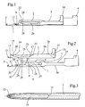
- Figure 1 is a side view of the needle slides.
- Figure 2 shows the needle and the slide separate from each other.
- Figure 3 is an enlarged top view of the front part of the slide.
- Figures 4 to 11 show eight successive positions of the slide relative to the needle of a position extreme to the other especially in the case of a transfer of mesh.
- the sliding needle consists of a needle 1 and a slide 2 overlapping the needle 1 so similar to the sliding needle slide described in document EP-A-0 881 315.
- runner 2 has an inverted U-shaped profile, but over only part of its length for reasons which will appear later.
- the needle 1 is provided, in a conventional manner, of a hook 3.
- the needle 1 is provided with a heel 4 for its driven by the cams of a cam holder.
- the needle could however be driven by a key.
- the needle is provided an arm 5 extending forwards, above the needle proper, parallel to the axis longitudinal of the needle, i.e. to the direction displacement of this needle in its needle bed.
- the needle 1 and the arm 5 form a fork 6 of which the inner sides 7 and 8 have a non-contoured straight, cam-shaped.
- the 7-shaped side cam extends beyond the fork 6 where it has a depression 9 followed by a ramp 10 rising towards forward. In front of this ramp 10, the needle goes thinning, in known manner, along a ramp downward 11 to hook 3.
- the slide 2 has at the front a spout 12 located in front a shoulder 13 and it is provided at the rear with a heel 14 for his training.
- the back of the slide 2 is deleted in two places, on the one hand in its distal part, in front of a point 15 located slightly behind the shoulder 13 and, on the other hand, in its rear half 16, between heel 14 and a point 17 located approximately halfway down the runner.
- Interruption 16 at the bottom of the slide forms a width cut corresponding to the thickness of the needle. This cut is crossed by the arm 5 of the needle which extends above the slide proper, i.e. from area 29 of the slide in which the bottom of the slide is not interrupted. This zone 29 presents externally, at the front a ramp 19 terminated by a nose 20 and, at the rear, a slight boss 21. Internally, the bottom of the slide has a first boss 22 in its front part and a second boss 23 at the rear. Between these bosses the bottom of the slide shows a slight depression.
- runner 2 has two supporting points 33 and 34 cooperating respectively with the upper 35 and lower sides 36 of the needle body to prevent tipping untimely backstage. These support points can further be used to induce movement additional backstage relative to the needle, for example to retract his heel 14 relative to a cam of the cam carriage or for get a finer and more precise movement of its beak 12.
- at least one of the sides 35, 36 of the body of the needle is not straight, that is to say shaped cam.
- the fulcrum 33 is formed by a boss from the bottom of the slide and the fulcrum 34 is formed, for example, by repelling material from runner walls.
- zone 29 of the slide is located in the fork 6 of the needle, which ensures the non-rectilinear guide of the slide 2 during its displacement.
- the slide is shown in its rearmost position on the needle. In this position, the boss 24 of the arm 5 of the needle is in contact with the nose 20 of the slide, which has the effect of positioning the spout 12 of the slides in a low position with minimum height relative to the needle. In this position, the two sides of the nozzle 12 are separated by the needle 1 and thus the spout 12 and the depression located behind this beak are found at all points below the edge upper needle.
- the slide 2 is positioned in the fork 6 by its nose 20 and its boss 22.
- the spout 12 of the slide open, is located below the upper edge of needle 1.
- the two sides of the spout 12 rest on the sides of the needle on two millings 30 which reduce the thickness of the needle and therefore the opening of the spout 12 so as not to exceed the width of the slides.
- the mesh 31 is carried by needle 1 so that it exerts no pressure on slide 2 which is cantilevered and prevents braking of the slide.
- the spout 12 is located at that moment at a height H1 from the edge lower of the needle, i.e. compared to the bottom of the groove of the needle bed in which slides the needle. This level H1 is the minimum level of the nozzle 12 on the path of the slide.
- the slide 2 continues its advance by relying on the constant level upper part 26 of the needle, that is to say by keeping the level H2, as shown in Figure 6.
- slide 2 comes over the hook 3 of the needle by its beak 12, as represented in figure 8.
- This movement corresponds to the closing movement of a conventional needle valve by its valve.
- the mesh 31 can be entered by an opposite needle (carryover) or by a slide (punching) as described in the Patent EP 0 881 315, that is to say by the introduction of this needle or this slide in the spout 12.
- the slide could totally overlap the needle and it could be with two or more heels. Behind the scenes could present, at the rear, a single point of support, by example support point 34 (figure 2)
Landscapes
- Engineering & Computer Science (AREA)
- Textile Engineering (AREA)
- Knitting Machines (AREA)
- Infusion, Injection, And Reservoir Apparatuses (AREA)
Abstract
Description
L'invention concerne une aiguille à coulisse pour machine à tricoter comprenant une aiguille munie d'un crochet et une coulisse chevauchant au moins partiellement l'aiguille et munie d'au moins un talon, d'un bec et d'un épaulement, le fond de cette coulisse étant fendu longitudinalement dans sa région distale comprenant le bec et l'épaulement de manière à permettre l'écartement du bec par l'aiguille ou par une aiguille ou une coulisse opposées, la coulisse étant déplaçable relativement à l'aiguille pour fermer et ouvrir le crochet de l'aiguille et pour entraíner une maille par son épaulement.The invention relates to a sliding needle for knitting machine comprising a needle provided with a hook and a slide overlapping at least partially the needle and provided with at least one heel, a beak and a shoulder, the bottom of this slide being split longitudinally in its distal region comprising the spout and the shoulder so as to allow the nozzle to be moved apart by the needle or by a opposite needle or slide, the slide being movable relative to the needle to close and open the hook of the needle and to train a mesh by his shoulder.
Une telle aiguille est décrite dans la demande de brevet EP 0 881 315 au nom du demandeur. Dans l'exécution décrite dans ce document le fond de la coulisse et le bord supérieur de l'aiguille sont rectilignes et parallèles à la direction de déplacement de l'aiguille. Le déplacement de la coulisse est donc également rectiligne et parallèle à la direction de déplacement de l'aiguille. En raison de cette conformation, lorsque l'aiguille avance relativement à la coulisse pour venir en position de préparation de report de maille, la maille à reporter doit monter sur une rampe de l'aiguille jusqu'à ce qu'elle se trouve pratiquement au niveau du fond de la coulisse. Ceci a pour effet d'exercer sur la maille une traction vers le haut qui a pour effet d'agrandir la maille. Cet effet est encore renforcé lorsque la coulisse avance en entraínant la maille au-dessus du crochet de l'aiguille, le bec et l'épaulement de la coulisse passant largement au-dessus du crochet de l'aiguille. La finesse des mailles susceptibles d'être tricotée est donc limitée.Such a needle is described in the application for Patent EP 0 881 315 in the name of the applicant. In the execution described in this document the bottom of the slide and the upper edge of the needle are straight and parallel to the direction of travel of the needle. The displacement of the slide is therefore also straight and parallel to the direction of moving the needle. Because of this conformation, when the needle advances relative to the backstage to come in the preparation position of transfer of mesh, the mesh to be transferred must go up on a needle ramp until it sits practically at the bottom of the slide. This has for effect of exerting on the mesh a traction towards the high which has the effect of enlarging the mesh. This effect is further reinforced when the slide advances entraining the mesh above the hook the needle, the beak and the shoulder of the slide passing well above the needle hook. The fineness of the knits that can be knitted is therefore limited.
Dans une aiguille à coulisse de type antérieur
conventionnel, c'est-à-dire dans laquelle l'aiguille,
en forme de glissière, munie d'un crochet d'aiguille
est située sous un coulisseau venant fermer et ouvrir
le crochet, il a été proposé, dans le brevet FR 2 652
593, de prévoir des moyens pour élever et abaisser le
coulisseau relativement au fond de la rainure de
l'aiguille de manière à réduire le frottement et la
traction sur la maille portée par l'aiguille et obtenir
des mailles plus régulières. Ces moyens sont
constitués, d'une part, par un appui dans le fond de la
rainure de l'aiguille et, d'autre part, par un effet de
levier exercé par le poussoir de l'aiguille. La
trajectoire de l'extrémité du coulisseau n'est
toutefois pas assurée de manière suffisamment précise
et de plus, en raison de la conception générale de
l'aiguille, le coulisseau ne peut pas se déplacer au-delà
du crochet de l'aiguille, mais n'effectue qu'un
mouvement de va et vient entre une position basse et
une position haute, relativement au fond de la
coulisse.In an anterior type sliding needle
conventional, that is to say in which the needle,
slide-shaped, with needle hook
is located under a slide that closes and opens
the hook, it has been proposed, in
La présente invention a également pour but de permettre de tricoter des mailles plus fines et plus régulières, et, de plus, de faciliter les transferts de mailles vers un ou plusieurs éléments de réception. The present invention also aims to allow to knit finer and more regular stitches, and, moreover, to facilitate mesh transfers to one or more receiving elements.
A cet effet, l'aiguille à coulisse selon l'invention est caractérisée en ce qu'elle présente des moyens de positionnement et de guidage vertical de la coulisse en toutes positions de la coulisse lors de son déplacement relatif par rapport à l'aiguille, ces moyens de guidage et de positionnement vertical étant exclusivement et intégralement constitués par des formes particulières de l'aiguille et de la coulisse et tels que la coulisse se déplace selon une trajectoire en tous points contrôlée non rectiligne présentant des élévations et des abaissements.To this end, the sliding needle according to the invention is characterized in that it has means of positioning and vertical guide of the slide in all positions of the slide during its movement relative to the needle, these guide means and vertical positioning being exclusively and integrally formed by particular forms needle and runner and such as runner moves along a trajectory at all points controlled non-straight with elevations and cuts.
En assurant un guidage parfaitement contrôlé de la coulisse, ces moyens de guidage ont pour effet de réduire autant qu'il est possible la traction verticale sur la maille et, par conséquent son agrandissement. Il est ainsi possible de tricoter des mailles plus fines et plus régulières.By ensuring perfectly controlled guidance of the slides, these guide means have the effect of reduce vertical traction as much as possible on the mesh and, consequently, its enlargement. he it is thus possible to knit finer stitches and more regular.
Selon un mode d'exécution préféré de l'invention, le fond de la coulisse est ouvert entre le talon et environ le milieu de la coulisse et l'aiguille présente un bras s'étendant de l'arrière vers l'avant, sensiblement parallèlement au corps de l'aiguille, ce bras traversant la coulisse par son fond ouvert pour s'étendre au-dessus de la partie pleine de la coulisse de manière à former, avec le corps de l'aiguille, une fourche dans laquelle est guidée la coulisse.According to a preferred embodiment of the invention, the bottom of the slide is open between the heel and about the middle of the slide and the needle is an arm extending from back to front, substantially parallel to the body of the needle, this arms crossing the slide by its open bottom for extend over the full part of the slide so as to form, with the body of the needle, a fork in which the slide is guided.
Pour assurer le guidage, les côtés intérieurs de ladite fourche, ainsi que le fond et le dos de la partie pleine de la coulisse, sont avantageusement en forme de cames assurant le mouvement non rectiligne de la coulisse, c'est-à-dire son élévation et son abaissement relativement à l'aiguille.To provide guidance, the interior sides of said fork, as well as the bottom and back of the part full of the slide, are advantageously shaped cams ensuring the non-rectilinear movement of the slide, i.e. its rise and fall relative to the needle.
Selon un mode d'exécution, la coulisse présente, à l'arrière, au moins un point d'appui coopérant avec le corps de l'aiguille pour empêcher le basculement intempestif de la coulisse et/ou pour induire un déplacement dans un plan vertical de l'arrière de la coulisse relativement à l'aiguille. Dans ce dernier cas, l'un des côtés au moins du corps de l'aiguille sur lequel s'appuie le point d'appui est en forme de came.According to one embodiment, the slide presents, at the rear, at least one fulcrum cooperating with the needle body to prevent tipping inadvertent of the slide and / or to induce a displacement in a vertical plane of the rear of the slides relative to the needle. In this last case, at least one of the sides of the needle body on which rests on the fulcrum is cam-shaped.
Le dessin annexé représente, à titre d'exemple, un mode d'exécution de l'invention.The accompanying drawing shows, by way of example, a mode of the invention.
La figure 1 est une vue latérale de l'aiguille à coulisse.Figure 1 is a side view of the needle slides.
La figure 2 représente l'aiguille et la coulisse séparées l'une de l'autre.Figure 2 shows the needle and the slide separate from each other.
La figure 3 est une vue de dessus, agrandie, de la partie antérieure de la coulisse.Figure 3 is an enlarged top view of the front part of the slide.
Les figures 4 à 11 montrent huit positions successives de la coulisse relativement à l'aiguille d'une position extrême à l'autre en particulier dans le cas d'un report de maille.Figures 4 to 11 show eight successive positions of the slide relative to the needle of a position extreme to the other especially in the case of a transfer of mesh.
La forme de l'aiguille et de la coulisse sera tout d'abord décrite en relation aux figures 1 à 3. The shape of the needle and the slide will be all first described in relation to Figures 1 to 3.
L'aiguille à coulisse est constituée d'une aiguille 1
et d'une coulisse 2 chevauchant l'aiguille 1 de manière
similaire à la coulisse de l'aiguille à coulisse
décrite dans le document EP-A-0 881 315. A cet effet,
la coulisse 2 présente un profil en U renversé, mais
sur une partie seulement de sa longueur pour des
raisons qui apparaítront plus loin.The sliding needle consists of a
L'aiguille 1 est munie, de manière conventionnelle,
d'un crochet 3. Dans le mode d'exécution représenté,
l'aiguille 1 est munie d'un talon 4 pour son
entraínement par les cames d'un porte-cames. L'aiguille
pourrait cependant être entraínée par une clavette.
Approximativement en son milieu, l'aiguille est munie
d'un bras 5 s'étendant vers l'avant, au-dessus de
l'aiguille proprement dite, parallèlement à l'axe
longitudinal de l'aiguille, c'est-à-dire à la direction
de déplacement de cette aiguille dans sa fonture.
L'aiguille 1 et le bras 5 forment une fourche 6 dont
les côtés intérieurs 7 et 8 présentent un contour non
rectiligne, en forme de came. Le côté 7 en forme de
came se prolonge au-delà de la fourche 6 où il présente
une dépression 9 suivie d'une rampe 10 s'élevant vers
l'avant. En avant de cette rampe 10, l'aiguille va
s'amincissant, de manière connue, selon une rampe
descendante 11 jusqu'au crochet 3.The
La coulisse 2 présente à l'avant un bec 12 situé devant
un épaulement 13 et elle est munie à l'arrière d'un
talon 14 pour son entraínement. Le fond de la coulisse
2 est supprimé en deux endroits, d'une part dans sa
partie distale, en avant d'un point 15 situé légèrement
en arrière de l'épaulement 13 et, d'autre part, dans sa
moitié arrière 16, entre le talon 14 et un point 17
situé approximativement à mi-longueur de la coulisse.The
Vue de dessus, la partie distale de la coulisse est
représentée à la figure 3. L'interruption du profil en
U de la coulisse forme une fente 18 qui se rétrécit à
l'extrémité de la coulisse pour former le bec 12 à
l'extrémité duquel les côtés de la fente 18 se
rejoignent. Les deux côtés de la fente 18 peuvent
s'écarter l'un de l'autre élastiquement.Top view, the distal part of the slide is
represented in figure 3. The interruption of the profile in
U of the slide forms a
L'interruption 16 du fond de la coulisse forme une
découpe de largeur correspondant à l'épaisseur de
l'aiguille. Cette découpe est traversée par le bras 5
de l'aiguille qui s'étend au-dessus de la coulisse
proprement dite, c'est-à-dire de la zone 29 de la
coulisse dans laquelle le fond de la coulisse n'est pas
interrompu. Cette zone 29 présente extérieurement, à
l'avant une rampe 19 terminée par un nez 20 et, à
l'arrière, un léger bossage 21. Intérieurement, le fond
de la coulisse présente un premier bossage 22 dans sa
partie avant et un second bossage 23 à l'arrière. Entre
ces bossages le fond de la coulisse présente une légère
dépression.
A l'arrière, à la hauteur du talon 14, la coulisse 2
présente deux points d'appui 33 et 34 coopérant
respectivement avec les côtés supérieur 35 et inférieur
36 du corps de l'aiguille pour éviter le basculement
intempestif de la coulisse. Ces points d'appui peuvent
en outre être utilisés pour induire un mouvement
supplémentaire de la coulisse relativement à
l'aiguille, par exemple pour escamoter son talon 14
relativement à une came du chariot porte-cames ou pour
obtenir un mouvement plus fin et plus précis de son bec
12. Dans ce cas au moins l'un des côtés 35, 36 du corps
de l'aiguille est non rectiligne, c'est-à-dire en forme
de came. Le point d'appui 33 est formé par un bossage
du fond de la coulisse et le point d'appui 34 est
formé, par exemple, par repoussage de la matière des
parois de la coulisse.Back, at
En ce qui concerne le profil intérieur de la fourchette
6 de l'aiguille, il présente, à partir de l'extrémité
du bras 5, une rampe de dégagement 32 suivie d'un
bossage 24, puis d'une légère dépression et d'un second
bossage 25 faiblement marqué et, sur l'aiguille
proprement dite, une partie haute 26 de niveau constant
entre la dépression 9 et une rampe 27 aboutissant à une
dépression 28.Regarding the inner profile of the
Comme on peut le voir à la figure 1, lorsque l'aiguille
est assemblée, la zone 29 de la coulisse est située
dans la fourchette 6 de l'aiguille, laquelle assure le
guidage non rectiligne de la coulisse 2 lors de son
déplacement. A la figure 1, la coulisse est représentée
dans sa position la plus en arrière sur l'aiguille.
Dans cette position, le bossage 24 du bras 5 de
l'aiguille est en appui sur le nez 20 de la coulisse,
ce qui a pour effet de positionner le bec 12 de la
coulisse dans une position basse de hauteur minimale
relativement à l'aiguille. Dans cette position, les
deux côtés du bec 12 sont écartés par l'aiguille 1 et
ainsi le bec 12 et la dépression située en arrière de
ce bec se trouvent en tous points en dessous du bord
supérieur de l'aiguille.As can be seen in Figure 1, when the needle
is assembled,
Le mouvement complet de la coulisse sur l'aiguille sera maintenant décrit en relation aux figures 4 à 11 qui représentent huit positions successives de la coulisse relativement à l'aiguille à partir de la position représentée à la figure 1 qui est la même position que celle représentée à la figure 4.The full movement of the slide on the needle will be now described in relation to Figures 4 to 11 which represent eight successive positions of the slide relative to the needle from the position shown in Figure 1 which is the same position as that shown in Figure 4.
La séquence représentée illustre un report de maille.The sequence shown illustrates a carry over.
Dans la position représentée à la figure 4, la coulisse
2 est positionnée dans la fourchette 6 par son nez 20
et son bossage 22. Le bec 12 de la coulisse, ouvert,
est situé en dessous du bord supérieur de l'aiguille 1.
Les deux côté du bec 12 s'appuient sur les côtés de
l'aiguille sur deux fraisages 30 qui réduisent
l'épaisseur de l'aiguille et par conséquent l'ouverture
du bec 12 de manière à ne pas dépasser la largeur de la
coulisse. La maille à reporter 31 est portée par
l'aiguille 1 de sorte qu'elle n'exerce aucune pression
sur la coulisse 2 qui se trouve en porte-à-faux et
évite un freinage de la coulisse. Le bec 12 se trouve à
ce moment là à une hauteur H1 par rapport au bord
inférieur de l'aiguille, c'est-à-dire par rapport au
fond de la rainure de la fonture dans laquelle coulisse
l'aiguille. Ce niveau H1 est le niveau minimal du bec
12 sur la trajectoire de la coulisse. In the position shown in Figure 4, the
Lorsque la coulisse 2 avance, son bossage 22 monte sur
la rampe 27 de l'aiguille pour arriver sur la partie
haute 26 (figure 5). Vers le haut, la coulisse est
retenue et guidée par le bossage 24 du bras 5 de
l'aiguille. Cette ascension de la coulisse est juste
suffisante pour que la dépression à l'arrière du bec 12
de la coulisse arrive légèrement au dessus du niveau de
l'aiguille. Lors de cette ascension de la coulisse, le
bec 12 se referme et la maille 31 est entraínée par
l'épaulement 13 de la coulisse. Le niveau H2 atteint
par le bec 12 de la coulisse est le niveau le plus haut
relativement à l'aiguille atteint par la coulisse lors
de son déplacement.When the
La coulisse 2 poursuit sont avance en s'appuyant sur la
partie haute de niveau constant 26 de l'aiguille,
c'est-à-dire en conservant le niveau H2, comme
représenté à la figure 6.The
Le bossage 22 de la coulisse quitte ensuite la partie
26 de l'aiguille de telle sorte que le bec 12 de la
coulisse descend en direction du crochet 3 de
l'aiguille, comme représenté à la figure 7.The
Poursuivant sa descente, la coulisse 2 vient coiffer le
crochet 3 de l'aiguille par son bec 12, comme
représenté à la figure 8. Ce mouvement correspond au
mouvement de fermeture d'une aiguille conventionnelle à
clapet par son clapet.Continuing its descent,
La coulisse poursuivant sa progression, son bossage 22
arrive contre la rampe 10 de l'aiguille de telle sorte
que la coulisse 2 et son bec 12 amorcent un mouvement
ascendant (figure 9) qui se poursuit jusqu'à ce que le
bec 12 atteint un niveau H4 (figure 10). Ce mouvement
ascendant a pour but d'éviter que le crochet 3 de
l'aiguille accroche des filaments de la maille 31
présente sur la coulisse.The backstage continuing to progress, its
Une fois le crochet 3 passé, le bossage 22 de la
coulisse 2 redescend le long de la rampe 11 de
l'aiguille et la quitte alors que le bossage 23 prend
le relais sur la face 26 de l'aiguille et le bec 12
atteint un niveau bas H5 et conserve ce niveau jusqu'au
bout de son déplacement. Cette descente a pour effet
d'éviter une déformation, par traction, de la maille 31
(figure 11).Once the
Dans la position représentée à la figure 11 la maille
31 peut être saisie par une aiguille opposée (report)
ou par une coulisse (poinçonnage) comme décrit dans le
brevet EP 0 881 315, c'est-à-dire par l'introduction de
cette aiguille ou de cette coulisse dans le bec 12.In the position shown in Figure 11 the
Dans des variantes d'exécution, la coulisse pourrait chevaucher totalement l'aiguille et elle pourrait être munie de deux talons ou plus. La coulisse pourrait présenter, à l'arrière, un seul point d'appui, par exemple le point d'appui 34 (figure 2)In execution variants, the slide could totally overlap the needle and it could be with two or more heels. Behind the scenes could present, at the rear, a single point of support, by example support point 34 (figure 2)
Claims (8)
caractérisée en ce qu'elle présente des moyens de positionnement et de guidage vertical (6) de la coulisse (2) en toutes positions de la coulisse lors de son déplacement relatif par rapport à l'aiguille (1), ces moyens de guidage et de positionnement vertical étant exclusivement et intégralement constitués par des formes particulières de l'aiguille et de la coulisse et tels que la coulisse se déplace selon une trajectoire en tous points contrôlée non rectiligne présentant des élévations et des abaissements.Sliding needle for a knitting machine comprising a needle (1) provided with a hook (3) and a slide (2) at least partially overlapping the needle and provided with at least one heel (14), a beak (12) and a shoulder (13), the bottom of the slide being split longitudinally in its distal region comprising the spout (12) and the shoulder (13) so as to allow the spout to be separated, the slide being movable relative to the needle to close and open the hook of the needle and to cause a stitch by its shoulder,
characterized in that it has means for positioning and vertical guidance (6) of the slide (2) in all positions of the slide during its relative movement relative to the needle (1), these guide means and of vertical positioning being exclusively and integrally constituted by particular shapes of the needle and of the slide and such that the slide moves according to a non-rectilinear controlled path in all points having rises and falls.
Applications Claiming Priority (2)
| Application Number | Priority Date | Filing Date | Title |
|---|---|---|---|
| FR0102272A FR2821093B1 (en) | 2001-02-20 | 2001-02-20 | SLIDING NEEDLE FOR KNITTING MACHINE |
| FR0102272 | 2001-02-20 |
Publications (2)
| Publication Number | Publication Date |
|---|---|
| EP1233093A1 true EP1233093A1 (en) | 2002-08-21 |
| EP1233093B1 EP1233093B1 (en) | 2005-11-23 |
Family
ID=8860219
Family Applications (1)
| Application Number | Title | Priority Date | Filing Date |
|---|---|---|---|
| EP02405107A Expired - Lifetime EP1233093B1 (en) | 2001-02-20 | 2002-02-13 | Sliding-tongue compound needle for a knitting machine |
Country Status (13)
| Country | Link |
|---|---|
| US (1) | US6510712B2 (en) |
| EP (1) | EP1233093B1 (en) |
| JP (1) | JP4121286B2 (en) |
| KR (1) | KR100825062B1 (en) |
| CN (1) | CN1272494C (en) |
| AT (1) | ATE310844T1 (en) |
| BR (1) | BR0200461A (en) |
| DE (1) | DE60207454T2 (en) |
| EA (1) | EA004389B1 (en) |
| ES (1) | ES2252417T3 (en) |
| FR (1) | FR2821093B1 (en) |
| HK (1) | HK1049030A1 (en) |
| TW (1) | TW553231U (en) |
Cited By (2)
| Publication number | Priority date | Publication date | Assignee | Title |
|---|---|---|---|---|
| DE112005003021B4 (en) | 2004-12-09 | 2019-04-25 | Shima Seiki Mfg., Ltd. | Flat knitting machine |
| EP3904578A1 (en) * | 2020-04-29 | 2021-11-03 | Groz-Beckert KG | Compound needle for knitting machines |
Families Citing this family (16)
| Publication number | Priority date | Publication date | Assignee | Title |
|---|---|---|---|---|
| JP4010169B2 (en) * | 2002-04-09 | 2007-11-21 | 三菱自動車工業株式会社 | Body structure |
| CN100436688C (en) * | 2002-12-20 | 2008-11-26 | 株式会社岛精机制作所 | Compound needle |
| JP3983720B2 (en) * | 2003-06-25 | 2007-09-26 | 株式会社島精機製作所 | Compound needle |
| JP4180541B2 (en) | 2004-03-31 | 2008-11-12 | 株式会社島精機製作所 | Pile knitting method with flat knitting machine |
| EP1757721B2 (en) † | 2005-08-26 | 2015-12-30 | H. Stoll GmbH & Co. KG | Method for stitch transfer |
| JP5732316B2 (en) * | 2010-06-18 | 2015-06-10 | 株式会社島精機製作所 | Compound needle of flat knitting machine |
| JP5766430B2 (en) * | 2010-11-22 | 2015-08-19 | 株式会社島精機製作所 | Compound needle of flat knitting machine |
| JP5618778B2 (en) * | 2010-11-22 | 2014-11-05 | 株式会社島精機製作所 | Compound needle of flat knitting machine |
| DE102013105239A1 (en) * | 2013-05-22 | 2014-11-27 | Groz-Beckert Kg | needle |
| CN103334223A (en) * | 2013-07-04 | 2013-10-02 | 宁波慈星股份有限公司 | Knitting needle for flat knitting machine |
| EP3597807B1 (en) * | 2018-07-18 | 2021-02-24 | Groz-Beckert KG | Machine knitting tool, in particular machine knitting needle |
| TWI726304B (en) * | 2018-08-20 | 2021-05-01 | 大康織機股份有限公司 | Mechanism for the transfer of stitches from the needles of knitting machine and sewing |
| CN109750414B (en) * | 2019-02-28 | 2024-02-06 | 宁波慈星股份有限公司 | Compound needle of flat knitting machine |
| CN109706615B (en) * | 2019-02-28 | 2023-09-29 | 宁波慈星股份有限公司 | Compound needle in flat knitting machine |
| CN109750413B (en) * | 2019-02-28 | 2023-09-29 | 宁波慈星股份有限公司 | Composite needle for flat knitting machine |
| CN110438655B (en) * | 2019-08-13 | 2024-04-02 | 宁波慈星股份有限公司 | Compound needle of flat knitting machine |
Citations (4)
| Publication number | Priority date | Publication date | Assignee | Title |
|---|---|---|---|---|
| FR2652593A1 (en) * | 1989-10-03 | 1991-04-05 | Shima Seiki Mfg | COMBINED KNITTING NEEDLE. |
| EP0496048A1 (en) * | 1991-01-15 | 1992-07-29 | Theodor Groz & Söhne & Ernst Beckert Nadelfabrik Commandit-Gesellschaft | Slider needle specially for knitting machines |
| EP0881315A2 (en) * | 1997-05-27 | 1998-12-02 | Atelier De Construction Steiger S.A. | Sliding-tongue needles for knitting machine |
| EP0881314A2 (en) * | 1997-05-27 | 1998-12-02 | Shima Seiki Manufacturing, Ltd. | A method for holding a stitch loop |
Family Cites Families (7)
| Publication number | Priority date | Publication date | Assignee | Title |
|---|---|---|---|---|
| CS151111B1 (en) * | 1970-12-22 | 1973-09-17 | ||
| DE3325767C1 (en) * | 1983-07-16 | 1984-11-08 | Theodor Groz & Söhne & Ernst Beckert Nadelfabrik KG, 7470 Albstadt | Slider needle for stitch-forming textile machines |
| JPH09228206A (en) * | 1995-12-22 | 1997-09-02 | Shima Seiki Mfg Ltd | Complex needle for knitting machine |
| DE19605581A1 (en) * | 1996-02-15 | 1997-08-21 | Bayer Ag | Insecticidal compositions based on polymers |
| US5937673A (en) * | 1997-05-01 | 1999-08-17 | Shima Seiki Manufacturing, Ltd. | Compound needle of a flat knitting machine |
| DE19913822C2 (en) * | 1999-03-26 | 2001-02-22 | Groz Beckert Kg | Slide needle with split slide |
| WO2000063476A1 (en) * | 1999-04-15 | 2000-10-26 | Shima Seiki Mfg., Ltd. | Compound needle of knitting machine |
-
2001
- 2001-02-20 FR FR0102272A patent/FR2821093B1/en not_active Expired - Fee Related
-
2002
- 2002-02-13 EP EP02405107A patent/EP1233093B1/en not_active Expired - Lifetime
- 2002-02-13 AT AT02405107T patent/ATE310844T1/en not_active IP Right Cessation
- 2002-02-13 ES ES02405107T patent/ES2252417T3/en not_active Expired - Lifetime
- 2002-02-13 DE DE60207454T patent/DE60207454T2/en not_active Expired - Lifetime
- 2002-02-19 KR KR1020020008652A patent/KR100825062B1/en not_active IP Right Cessation
- 2002-02-19 EA EA200200181A patent/EA004389B1/en not_active IP Right Cessation
- 2002-02-19 US US10/079,622 patent/US6510712B2/en not_active Expired - Lifetime
- 2002-02-19 JP JP2002041609A patent/JP4121286B2/en not_active Expired - Lifetime
- 2002-02-19 TW TW092202666U patent/TW553231U/en not_active IP Right Cessation
- 2002-02-20 CN CNB021051038A patent/CN1272494C/en not_active Expired - Lifetime
- 2002-02-20 BR BR0200461-5A patent/BR0200461A/en not_active Application Discontinuation
-
2003
- 2003-02-18 HK HK03101170A patent/HK1049030A1/en not_active IP Right Cessation
Patent Citations (4)
| Publication number | Priority date | Publication date | Assignee | Title |
|---|---|---|---|---|
| FR2652593A1 (en) * | 1989-10-03 | 1991-04-05 | Shima Seiki Mfg | COMBINED KNITTING NEEDLE. |
| EP0496048A1 (en) * | 1991-01-15 | 1992-07-29 | Theodor Groz & Söhne & Ernst Beckert Nadelfabrik Commandit-Gesellschaft | Slider needle specially for knitting machines |
| EP0881315A2 (en) * | 1997-05-27 | 1998-12-02 | Atelier De Construction Steiger S.A. | Sliding-tongue needles for knitting machine |
| EP0881314A2 (en) * | 1997-05-27 | 1998-12-02 | Shima Seiki Manufacturing, Ltd. | A method for holding a stitch loop |
Cited By (5)
| Publication number | Priority date | Publication date | Assignee | Title |
|---|---|---|---|---|
| DE112005003021B4 (en) | 2004-12-09 | 2019-04-25 | Shima Seiki Mfg., Ltd. | Flat knitting machine |
| EP3904578A1 (en) * | 2020-04-29 | 2021-11-03 | Groz-Beckert KG | Compound needle for knitting machines |
| WO2021219261A1 (en) * | 2020-04-29 | 2021-11-04 | Groz-Beckert Kg | Slide needle for knitting machines |
| CN115398052A (en) * | 2020-04-29 | 2022-11-25 | 格罗兹-贝克特公司 | Sliding needle for knitting machine |
| CN115398052B (en) * | 2020-04-29 | 2023-12-15 | 格罗兹-贝克特公司 | Sliding needle for knitting machine |
Also Published As
| Publication number | Publication date |
|---|---|
| EA200200181A1 (en) | 2002-12-26 |
| JP4121286B2 (en) | 2008-07-23 |
| US6510712B2 (en) | 2003-01-28 |
| BR0200461A (en) | 2002-10-29 |
| EP1233093B1 (en) | 2005-11-23 |
| ATE310844T1 (en) | 2005-12-15 |
| HK1049030A1 (en) | 2003-04-25 |
| JP2002294541A (en) | 2002-10-09 |
| FR2821093B1 (en) | 2003-05-09 |
| KR20020068278A (en) | 2002-08-27 |
| CN1272494C (en) | 2006-08-30 |
| TW553231U (en) | 2003-09-11 |
| DE60207454T2 (en) | 2006-07-20 |
| FR2821093A1 (en) | 2002-08-23 |
| KR100825062B1 (en) | 2008-04-25 |
| ES2252417T3 (en) | 2006-05-16 |
| CN1372028A (en) | 2002-10-02 |
| EA004389B1 (en) | 2004-04-29 |
| DE60207454D1 (en) | 2005-12-29 |
| US20020112509A1 (en) | 2002-08-22 |
Similar Documents
| Publication | Publication Date | Title |
|---|---|---|
| EP1233093B1 (en) | Sliding-tongue compound needle for a knitting machine | |
| FR2526727A1 (en) | SUNROOF OPENING ROOF AND RAIL FOR MOTOR VEHICLE | |
| EP3437703B1 (en) | Braking device for mountaineering ski | |
| EP0881315B1 (en) | Sliding-tongue needles for knitting machine | |
| EP0430821B1 (en) | Plastic ski boot | |
| EP0189602B1 (en) | Knitting machine | |
| EP1586708A2 (en) | Device for the coupling of a tool on the frame of a loader, in particular an agricultural loader. | |
| FR2652593A1 (en) | COMBINED KNITTING NEEDLE. | |
| CH675543A5 (en) | Safety binding for ski | |
| FR2656226A1 (en) | SECURITY FIXING FOR SKI. | |
| EP0498153B1 (en) | Safety ski binding | |
| FR2549102A1 (en) | DEVICE FOR SELECTING NEEDLES IN A KNITTING MACHINE, PARTICULARLY IN A STRETCHED KNITTING MACHINE | |
| FR2608494A1 (en) | Domestic food-slicing machine | |
| FR2465019A1 (en) | METHOD AND TOOL FOR REMOVING A CUTTER FROM THE RING OF A CONTINUOUSLY CONTINUOUSLY WIRED OR RING RETRACTRE | |
| FR2701014A1 (en) | Refuse collector with removable bag | |
| WO2009109886A1 (en) | Draw comb for rectilinear knitting machine | |
| FR2659536A1 (en) | SHOE OR SANDAL WITH INJECTED SOLE, METHOD FOR MANUFACTURING SAME AND DEVICE FOR IMPLEMENTING SAID METHOD | |
| FR2683120A1 (en) | TORQUE DEVICE FOR DESILEUSE. | |
| JP3665127B2 (en) | Combine grain feeder | |
| WO2020182529A1 (en) | Machine for preparing infused beverages provided with a lift-up filter basket | |
| FR2803768A1 (en) | Automatic fastening system for fixing boots on a snowboard has jaws locked in place by wedge which lodges against ledge on frame when open | |
| FR2560614A1 (en) | RECTILINE MACHINE | |
| FR3093630A1 (en) | INFUSED BEVERAGE PREPARATION MACHINE EQUIPPED WITH A ROTATING FILTER BASKET | |
| FR2590778A1 (en) | AUTOMATIC BLOCKING CURSOR FOR SLIDE CLOSURE | |
| FR2616748A1 (en) | MACHINE FOR PREFORMING BOXES IN CARDBOARD OR SIMILAR MATERIAL HAVING FLAT FOLDES AND BOX THAT CAN BE USED ON SUCH A MACHINE |
Legal Events
| Date | Code | Title | Description |
|---|---|---|---|
| PUAI | Public reference made under article 153(3) epc to a published international application that has entered the european phase |
Free format text: ORIGINAL CODE: 0009012 |
|
| AK | Designated contracting states |
Kind code of ref document: A1 Designated state(s): AT BE CH CY DE DK ES FI FR GB GR IE IT LI LU MC NL PT SE TR |
|
| AX | Request for extension of the european patent |
Free format text: AL;LT;LV;MK;RO;SI |
|
| 17P | Request for examination filed |
Effective date: 20021114 |
|
| AKX | Designation fees paid |
Designated state(s): AT BE CH CY DE DK ES FI FR GB GR IE IT LI LU MC NL PT SE TR |
|
| AXX | Extension fees paid |
Extension state: RO Payment date: 20021114 |
|
| 17Q | First examination report despatched |
Effective date: 20041028 |
|
| GRAP | Despatch of communication of intention to grant a patent |
Free format text: ORIGINAL CODE: EPIDOSNIGR1 |
|
| RTI1 | Title (correction) |
Free format text: SLIDING-TONGUE COMPOUND NEEDLE FOR A KNITTING MACHINE |
|
| GRAS | Grant fee paid |
Free format text: ORIGINAL CODE: EPIDOSNIGR3 |
|
| GRAA | (expected) grant |
Free format text: ORIGINAL CODE: 0009210 |
|
| AK | Designated contracting states |
Kind code of ref document: B1 Designated state(s): AT BE CH CY DE DK ES FI FR GB GR IE IT LI LU MC NL PT SE TR |
|
| AX | Request for extension of the european patent |
Extension state: RO |
|
| PG25 | Lapsed in a contracting state [announced via postgrant information from national office to epo] |
Ref country code: FI Free format text: LAPSE BECAUSE OF FAILURE TO SUBMIT A TRANSLATION OF THE DESCRIPTION OR TO PAY THE FEE WITHIN THE PRESCRIBED TIME-LIMIT Effective date: 20051123 Ref country code: AT Free format text: LAPSE BECAUSE OF FAILURE TO SUBMIT A TRANSLATION OF THE DESCRIPTION OR TO PAY THE FEE WITHIN THE PRESCRIBED TIME-LIMIT Effective date: 20051123 Ref country code: IE Free format text: LAPSE BECAUSE OF FAILURE TO SUBMIT A TRANSLATION OF THE DESCRIPTION OR TO PAY THE FEE WITHIN THE PRESCRIBED TIME-LIMIT Effective date: 20051123 Ref country code: NL Free format text: LAPSE BECAUSE OF FAILURE TO SUBMIT A TRANSLATION OF THE DESCRIPTION OR TO PAY THE FEE WITHIN THE PRESCRIBED TIME-LIMIT Effective date: 20051123 |
|
| REG | Reference to a national code |
Ref country code: GB Ref legal event code: FG4D Free format text: NOT ENGLISH |
|
| REG | Reference to a national code |
Ref country code: CH Ref legal event code: EP |
|
| REF | Corresponds to: |
Ref document number: 60207454 Country of ref document: DE Date of ref document: 20051229 Kind code of ref document: P |
|
| REG | Reference to a national code |
Ref country code: IE Ref legal event code: FG4D Free format text: LANGUAGE OF EP DOCUMENT: FRENCH |
|
| REG | Reference to a national code |
Ref country code: CH Ref legal event code: NV Representative=s name: BUGNION S.A. |
|
| PG25 | Lapsed in a contracting state [announced via postgrant information from national office to epo] |
Ref country code: GR Free format text: LAPSE BECAUSE OF FAILURE TO SUBMIT A TRANSLATION OF THE DESCRIPTION OR TO PAY THE FEE WITHIN THE PRESCRIBED TIME-LIMIT Effective date: 20060223 Ref country code: DK Free format text: LAPSE BECAUSE OF FAILURE TO SUBMIT A TRANSLATION OF THE DESCRIPTION OR TO PAY THE FEE WITHIN THE PRESCRIBED TIME-LIMIT Effective date: 20060223 Ref country code: SE Free format text: LAPSE BECAUSE OF FAILURE TO SUBMIT A TRANSLATION OF THE DESCRIPTION OR TO PAY THE FEE WITHIN THE PRESCRIBED TIME-LIMIT Effective date: 20060223 |
|
| PG25 | Lapsed in a contracting state [announced via postgrant information from national office to epo] |
Ref country code: MC Free format text: LAPSE BECAUSE OF NON-PAYMENT OF DUE FEES Effective date: 20060228 Ref country code: LU Free format text: LAPSE BECAUSE OF NON-PAYMENT OF DUE FEES Effective date: 20060228 |
|
| GBT | Gb: translation of ep patent filed (gb section 77(6)(a)/1977) |
Effective date: 20060329 |
|
| NLV1 | Nl: lapsed or annulled due to failure to fulfill the requirements of art. 29p and 29m of the patents act | ||
| REG | Reference to a national code |
Ref country code: ES Ref legal event code: FG2A Ref document number: 2252417 Country of ref document: ES Kind code of ref document: T3 |
|
| REG | Reference to a national code |
Ref country code: IE Ref legal event code: FD4D |
|
| PLBE | No opposition filed within time limit |
Free format text: ORIGINAL CODE: 0009261 |
|
| STAA | Information on the status of an ep patent application or granted ep patent |
Free format text: STATUS: NO OPPOSITION FILED WITHIN TIME LIMIT |
|
| 26N | No opposition filed |
Effective date: 20060824 |
|
| PG25 | Lapsed in a contracting state [announced via postgrant information from national office to epo] |
Ref country code: CY Free format text: LAPSE BECAUSE OF FAILURE TO SUBMIT A TRANSLATION OF THE DESCRIPTION OR TO PAY THE FEE WITHIN THE PRESCRIBED TIME-LIMIT Effective date: 20051123 |
|
| PGFP | Annual fee paid to national office [announced via postgrant information from national office to epo] |
Ref country code: PT Payment date: 20090205 Year of fee payment: 8 |
|
| REG | Reference to a national code |
Ref country code: CH Ref legal event code: PUE Owner name: STEIGER PARTICIPATIONS SA Free format text: ATELIER DE CONSTRUCTION STEIGER S.A.# #CH-1895 VIONNAZ (CH) -TRANSFER TO- STEIGER PARTICIPATIONS SA#ROUTE DU SIMPLON 20#1895 VIONNAZ (CH) |
|
| REG | Reference to a national code |
Ref country code: GB Ref legal event code: 732E Free format text: REGISTERED BETWEEN 20100708 AND 20100714 |
|
| REG | Reference to a national code |
Ref country code: PT Ref legal event code: MM4A Free format text: LAPSE DUE TO NON-PAYMENT OF FEES Effective date: 20100813 |
|
| BECA | Be: change of holder's address |
Owner name: STEIGER PARTICIPATIONS S.A.ROUTE DU SIMPLON 20, CH Effective date: 20100804 |
|
| BECH | Be: change of holder |
Owner name: STEIGER PARTICIPATIONS S.A. Effective date: 20100804 |
|
| REG | Reference to a national code |
Ref country code: GB Ref legal event code: 732E Free format text: REGISTERED BETWEEN 20100812 AND 20100818 |
|
| REG | Reference to a national code |
Ref country code: FR Ref legal event code: CD Ref country code: FR Ref legal event code: TP |
|
| PG25 | Lapsed in a contracting state [announced via postgrant information from national office to epo] |
Ref country code: PT Free format text: LAPSE BECAUSE OF NON-PAYMENT OF DUE FEES Effective date: 20100813 |
|
| PGFP | Annual fee paid to national office [announced via postgrant information from national office to epo] |
Ref country code: GB Payment date: 20130218 Year of fee payment: 12 |
|
| PGFP | Annual fee paid to national office [announced via postgrant information from national office to epo] |
Ref country code: BE Payment date: 20130301 Year of fee payment: 12 |
|
| PGFP | Annual fee paid to national office [announced via postgrant information from national office to epo] |
Ref country code: ES Payment date: 20140221 Year of fee payment: 13 |
|
| BERE | Be: lapsed |
Owner name: STEIGER PARTICIPATIONS S.A. Effective date: 20140228 |
|
| GBPC | Gb: european patent ceased through non-payment of renewal fee |
Effective date: 20140213 |
|
| PG25 | Lapsed in a contracting state [announced via postgrant information from national office to epo] |
Ref country code: GB Free format text: LAPSE BECAUSE OF NON-PAYMENT OF DUE FEES Effective date: 20140213 Ref country code: BE Free format text: LAPSE BECAUSE OF NON-PAYMENT OF DUE FEES Effective date: 20140228 |
|
| REG | Reference to a national code |
Ref country code: FR Ref legal event code: PLFP Year of fee payment: 14 |
|
| PGFP | Annual fee paid to national office [announced via postgrant information from national office to epo] |
Ref country code: IT Payment date: 20150225 Year of fee payment: 14 Ref country code: CH Payment date: 20150220 Year of fee payment: 14 |
|
| PGFP | Annual fee paid to national office [announced via postgrant information from national office to epo] |
Ref country code: TR Payment date: 20150209 Year of fee payment: 14 Ref country code: FR Payment date: 20150217 Year of fee payment: 14 |
|
| REG | Reference to a national code |
Ref country code: ES Ref legal event code: FD2A Effective date: 20160329 |
|
| PG25 | Lapsed in a contracting state [announced via postgrant information from national office to epo] |
Ref country code: ES Free format text: LAPSE BECAUSE OF NON-PAYMENT OF DUE FEES Effective date: 20150214 |
|
| REG | Reference to a national code |
Ref country code: CH Ref legal event code: PL |
|
| PG25 | Lapsed in a contracting state [announced via postgrant information from national office to epo] |
Ref country code: LI Free format text: LAPSE BECAUSE OF NON-PAYMENT OF DUE FEES Effective date: 20160229 Ref country code: CH Free format text: LAPSE BECAUSE OF NON-PAYMENT OF DUE FEES Effective date: 20160229 |
|
| REG | Reference to a national code |
Ref country code: FR Ref legal event code: ST Effective date: 20161028 |
|
| PG25 | Lapsed in a contracting state [announced via postgrant information from national office to epo] |
Ref country code: IT Free format text: LAPSE BECAUSE OF NON-PAYMENT OF DUE FEES Effective date: 20160213 |
|
| PG25 | Lapsed in a contracting state [announced via postgrant information from national office to epo] |
Ref country code: FR Free format text: LAPSE BECAUSE OF NON-PAYMENT OF DUE FEES Effective date: 20160229 |
|
| PGFP | Annual fee paid to national office [announced via postgrant information from national office to epo] |
Ref country code: DE Payment date: 20210126 Year of fee payment: 20 |
|
| REG | Reference to a national code |
Ref country code: DE Ref legal event code: R071 Ref document number: 60207454 Country of ref document: DE |
|
| PG25 | Lapsed in a contracting state [announced via postgrant information from national office to epo] |
Ref country code: TR Free format text: LAPSE BECAUSE OF NON-PAYMENT OF DUE FEES Effective date: 20160213 |